QBQENERGYEYEMT02Wireless Door/Window Sensor
Energy Eye Inc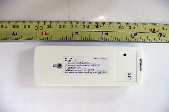
Click to zoom
Application Details
- Equipment Class
- DSC - Part 15 Security/Remote Control Transmitter
- Date of Grant
- May 07, 2002
- Application Purpose
- Original Equipment
- Date of Application
- May 07, 2002
- Equipment Note
- Wireless Door/Window Sensor
- Frequency Range
- 314.87700000 - 314.87700000
- Company
- Energy Eye Inc
- Country
- United States
Documents & Files
Document Text
Text extracted from the exhibit documents filed with the FCC. Open a document above to read the original.
Users Manual
© Copyright 2002 Electritech Inc. All Rights Reserved Energy Eye System User Manual V1.3 THIS DEVICE COMPLIES WITH PART 15 OF THE FCC RULES. OPERATION IS SUBJECT TO THE FOLLOWING TWO CONDITIONS: (1) THIS DEVICE MAY NOT CAUSE HARMFUL INTERFERENCE AND (2) THIS DEVICE MUST ACCEPT ANY INTERFERENCE RECEIVED, INCLUDING INTERFERENCE THAT MAY CAUSE UNDESIRED OPERATION © Copyright 2002 Electritech Inc. All Rights Reserved 1 User Manual Table of Contents I. Introduction 2 II. Product Overview and Descriptions 3 III. Product Placement and Mounting 5 IV. Jumper Settings for the Energy Eye System 6 V. Wiring the Energy Eye System 9 VI. Learning the Energy Eye Components 10 VII. Testing 12 VIII. Additional Information 12 Notes and Contact Information 13 © Copyright 2002 Electritech Inc. All Rights Reserved 2 I. Introduction Congratulations on the purchase of your Energy Eye System! Finally you can begin controlling your wasted guestroom electricity expenses using the most efficient system of its kind. The Energy Eye System uses passive infrared and door/window contact sensors to control wasted energy costs by setting back a guestroom’s HVAC (Heating, Ventilation, Air Conditioning) to an optimized level while guests are away. The Energy Eye System’s components communicate using radio frequency (RF) technology to minimize installation and maintenance costs. Because each property has different needs, the Energy Eye System allows for full customization of setbacks and timer settings that should be determined before installation. For any questions you may have that are not covered in this instruction manual please contact your distributor or Electritech’s Energy Eye product division directly at (USA) 1-866-463-3135. Warnings! • HVAC units may contain hazardous voltages of 120 VAC to 277 VAC. • To prevent personal injury and/or death, insure that all power is disconnected before installation and connection inside the HVAC unit . • The Energy Eye System should be installed by qualified personnel only. • All electrical connections and wiring must conform to the National Electrical Code and applicable local codes at the time of installation. • The Energy Eye receiver and sensors contain sensitive electronic components, DO NOT attempt to repair or clean with chemicals or abrasives. • DO NOT touch the infrared lens located inside the passive infrared sensor with your finger. • Be careful with any tools near or around your working/installation environment. Before you Install The most important decisions to consider before installing an Energy Eye system are: 1) Where each of the components in the system should be placed inside your guestrooms and if more than the standard components (refer to “Standard components” and “Product Placement” sections for detailed information) are required. 2) It is important to understand each component, how it works, and its limitations in order to ensure that the system functions correctly after installation. Because no two properties are exactly alike, make it a point to understand the particular physical layout of each guestroom and your operating environment. Required Tools *NOTE: Additional tools might be required depending on property construction type, local environment, HVAC accessibility and HVAC age. • Philips Screwdrivers (various sizes) • Wire cutter/stripper • Plastic Electrical tape • 1 set Electrical caps • 1 small coin (size of a U.S. Penny or Dime) • 1 set Sheet-metal screws (only if installing on metal door frame) © Copyright 2002 Electritech Inc. All Rights Reserved 3 II. Product Overview and Descriptions *Note: Each guestroom system operates independently on a spectrum of over 10,000 RF codes to insure no interference with a neighboring guestroom system. Brain Unit (Microprocessor and receiver) The processing receiver or “Brain” Unit is the most important part of the Energy Eye system. The Brain processes information sent to it by both the door and window sensor(s) and PIR sensor(s). It then communicates directly to the HVAC interfaced power pack in order to accurately control room temperature while guests are out. Functions of the Brain Unit include: • “Auto/Manual” switch that gives hotel/motel management and staff the ability to completely disable the system at will. • Low-battery indication lights that let hotel staff know when one or all of the Energy Eye wireless components is low on battery life. The GREEN light on the Brain Unit blinks continuously when one or more of a component’s battery life is low and solid GREEN when completely discharged and requires replacement. • Programmable setback timer intervals: 30 seconds, 5/10/15 minutes. • Temperature setback range: 50 to 90 degrees Fahrenheit with 5-degree increments. • Two (2) minute re-cycle timer feature for ease on PTAC compressor lifespan. • Built in YELLOW LED to see “Signal Reception” from Energy Eye™ components (PIR(s) and/or Door/Window Sensor(s)). • Mode A and B (custom management selected modes for both economic and generous control) • Internal thermostat temperature sensing. • Fuse: There is an internal fuse supplied in order to prevent damage to the Energy Eye™ system during any type of power fluctuation PIR (Passive Infrared People Sensor) Energy Eye’s passive infrared people sensor (PIR) is specially designed for detecting the presence of people in a room by omitting a tri-band infrared spectrum to cross- reference both motion and body heat. Like all Energy Eye wireless products, the PIR uses a 315MHz (RF) to communicate with the Brain unit. Once the PIR determines guestroom occupancy a signal is then instantly sent to the Brain unit to perform the appropriate function. The Energy Eye PIR has a detection range of approximately 24 - 30 ft. (8 - 10 meters) long and a maximum angle detection of 110 degrees. The PIR is powered by a standard 9V Lithium battery provided by Electritech Inc. For efficiency purposes, Energy Eye PIRs self- check their battery level. Low battery si…
Text truncated - open the document above for the full version.
Cover Letter(s)
From: etcemi [[email protected]] Sent: Monday, April 29, 2002 11:01 PM To: Mike Kuo Subject: Re: ELECTRITECH, INC., FCC ID:QBQENERGYEYEMT02, AN02T1994 Dear Mike, Thanks for your reviewing on our application. Please find below for our explanation: Question #1: Schematic Diagram is not readable. Please provide a clear copy of schematic diagram. ANS: Attached please find the clear copy of the schematics. Question #2: Two idential external photos are submitted. Please provide additonal photo to show the front of device. ANS.: Please find attached photo for front view. Question #3: User Manual does not contain information requried under 15.21 of FCC rules. Please provide revised user manual. ANS.: Please find attached file for added page for FCC statement. Question #4: Request for confidentiality box is checked on the TCB application form. However, in the file titled Authorization. Two idential agency authorization letter are included. Please provide a request for confidentiality letter and indicate which documents are to be withheld from public disclosure. ANS.: Attached please finsd the letter requesting confidentiality on schematics and block diagram. If you have any further questions, please kindly let me know. Best regards, K. C. Chen ETC/EMC Department II ----- Original Message ----- From: Mike Kuo To: K. C. (E-mail) ; Will Yauo (E-mail) Sent: Sunday, April 28, 2002 2:26 AM Subject: FW: ELECTRITECH, INC., FCC ID:QBQENERGYEYEMT02, AN02T1994 -----Original Message----- From: CERTADM Sent: Saturday, April 27, 2002 11:24 AM To: '[email protected]' Subject: ELECTRITECH, INC., FCC ID:QBQENERGYEYEMT02, AN02T1994 Notice_content ------------- Question #1: Schematic Diagram is not readable. Please provide a clear copy of schematic diagram. Question #2: Two idential external photos are submitted. Please provide additonal photo to show the front of device. Question #3: User Manual does not contain information requried under 15.21 of FCC rules. Please provide revised user manual. Question #4: Request for confidentiality box is checked on the TCB application form. However, in the file titled Authorization. Two idential agency authorization letter are included. Please provide a request for confidentiality letter and indicate which documents are to be withheld from public disclosure. Best Regards Mike Kuo / TCB Certifier The items indicated above must be submitted before processing can continue on the above referenced application. Failure to provide the requested information within 30 days of the original e-mail date may result in application dismissal and forfeiture of the filing fee. Also, please note that partial responses increase processing time and should not be submitted. Any questions about the content of this correspondence should be directed to the e-mail address listed below the name of the sender.
External Photos
ETC Report No.:ET91R-03-098-01 FCC ID.: QBQENERGYEYEMT02 Rev. No 1.0 CONSTRUCTED PHOTOS of EUT Top View of EUT Bottom View of EUT
ID Label/Location Info
Bottom View of EUT s This device complies with part 15 of the FCC rules. Operation is subject to the following two conditions: (1) This device may not cause harmful interference, and (2) This device must accept any interference received, including interference that may cause undesired operation. Model: EEMT02 FCC ID.: QBQENERGYEYEMT02 15mm 35mm
Internal Photos
ETC Report No.:ET91R-03-098-01 FCC ID.: QBQENERGYEYEMT02 Rev. No 1.0 CONSTRUCTED PHOTOS of EUT Internal View of EUT Component View of Main PCB ETC Report No.:ET91R-03-098-01 FCC ID.: QBQENERGYEYEMT02 Rev. No 1.0 CONSTRUCTED PHOTOS of EUT Solder View of Main PCB
Operational Description
The door and window sensors are used to identify when the main door (window or balcony door) has been opened and closed. Each standard Energy Eye TM System can be programmed to operate a maximum of three (3) Door and Window Sensor. At least one (1) sensor is required for the main guestroom door however an additional two (2) door and window sensors can be programmed to control additional window and or (sliding) doors. Like all Energy Eye TM wireless products, the door and window sensor(s) use a 315MHz (RF) to communicate with the Brain Unit. The door and window sensor have a communication range of approximately 24-30 ft. (8-10 meters) and are powered by a single 2450 lithium battery. The door and windo sensor(s) self-check their battery level Low battery signal is displayed by a flasing GREEN LED on the Brain Unit. A simple jumper setting inside the sensor itself makes the distinction between a primary door sensor and an additional door/window sensor easy.
Test Report
Rev. No 1.0 FCC Part 15 EMI TEST REPORT of E.U.T. : WIRELSS DOOR/WINDOW SENSOR FCC ID. : QBQENERGYEYEMT02 MODEL : EEMT02 Working Frequency : 314.877MHz for APPLICANT : ELECTRITECH, INC. ADDRESS : 1802 N. Carson St, Suite 212-2543, Carson City, NV 8071, U.S.A. Test Performed by ELECTRONICS TESTING CENTER, TAIWAN NO. 34, LIN 5, DING FU TSUN, LINKOU HSIANG TAIPEI HSIEN, TAIWAN, R.O.C. Tel:(02)26023052, 26023054 Fax:(02)26010910 Report Number : ET91R-03-098-01 ETC Report No.:ET91R-03-098-01 FCC ID.: QBQENERGYEYEMT02 Rev. No 1.0 TEST REPORT CERTIFICATION Applicant : ELECTRITECH, INC. 1802 N. Carson St, Suite 212-2543, Carson City, NV 8071, U.S.A. Manufacturer : AEONSTAR TECHNOLOGY CORP. 5F, NO. 1, LANE 155, SEC. 3, PEI SHEN RD., SHEN KENG HSIANG, TAIPEI HSIEN, TAIWAN, R.O.C. Description of EUT : a) Type of EUT : WIRELSS DOOR/WINDOW SENSOR b) Trade Name : ---- c) Model No. : EEMT02 d) FCC ID : QBQENERGYEYEMT02 e) Working Frequency : 314.877MHz f) Power Supply : DC 3V Battery Regulation Applied : FCC Rules and Regulations Part 15 Subpart C (2001) I HEREBY CERTIFY THAT; The data shown in this report were made in accordance with the procedures given in ANSI C63.4 and the energy emitted by the device was founded to be within the limits applicable. I assume full responsibility for accuracy and completeness of these data. Note : 1. The results of the testing report relate only to the items tested. 2. The testing report shall not be reproduced except in full, without the written approval of ETC. Issued Date : Apr. 23, 2002 Test Engineer : ( Jeff Chuang ) Approve & Authorized Signer : Will Yauo, Manager EMC Dept. II of ELECTRONICS TESTING CENTER, TAIWAN ETC Report No.:ET91R-03-098-01 FCC ID.: QBQENERGYEYEMT02 Rev. No 1.0 Table of Contents Page 1. GENERAL INFORMATION.....................................................................................................................................................1 1.1 PRODUCT DESCRIPTION...........................................................................................................................................................1 1.2 CHARACTERISTICS OF DEVICE:...............................................................................................................................................1 1.3 TEST METHODOLOGY..............................................................................................................................................................1 1.4 TEST FACILITY..........................................................................................................................................................................1 2. DEFINITION AND LIMITS.......................................................................................................................................................2 2.1 DEFINITION................................................................................................................................................................................2 2.2 RESTRICTED BANDS OF OPERATION.....................................................................................................................................2 2.3 LIMITATION...............................................................................................................................................................................2 2.4 LABELING REQUIREMENT.......................................................................................................................................................4 2.5 USER INFORMATION.................................................................................................................................................................4 3 SYSTEM TEST CONFIGURATION.........................................................................................................................................5 3.1 JUSTIFICATION..........................................................................................................................................................................5 3.2 DEVICES FOR TESTED SYSTEM...............................................................................................................................................5 4. RADIATED EMISSION MEASUREMENT.............................................................................................................................6 4.1 APPLICABLE STANDARD.........................................................................................................................................................6 4.2 MEASUREMENT PROCEDURE..................................................................................................................................................6 4.3 TEST DATA.................................................................................................................................................................................8 4.4 FIELD STRENGTH CALCULATION..........................................................................................................................................8 4.5 ACTIVATE TIME........................................................................................................................................................................9 4.6 CALCULATION OF DUTY FACTOR.........................................................................................................................................9 4.7 RADIATED TEST EQUIPMENT...............................................................................................................................................10 4.8 MEASURING INSTRUMENT SETUP.......................................................................................................................................10 4.9 RADIATED MEASUREMENT PHOTOS..............................................................................................................................…
Text truncated - open the document above for the full version.
Test Setup Photos
ETC Report No.:ET91R-03-098-01 FCC ID.: QBQENERGYEYEMT02 Rev. No 1.0 Radiated Measurement Photos
Contact Information
Applicant
Phillip Kopp(Director)
Test Firm
Electronics Testing Center, TaiwanWinpo Tsai
Technical Specifications
| # | Rule Parts | Frequency Range | Power Output |
|---|---|---|---|
| 1 | 15.231 | 314.877 MHz - 314.877 MHz | - |
Other Applications from Energy Eye Inc
QBQENERGYEYEIR05
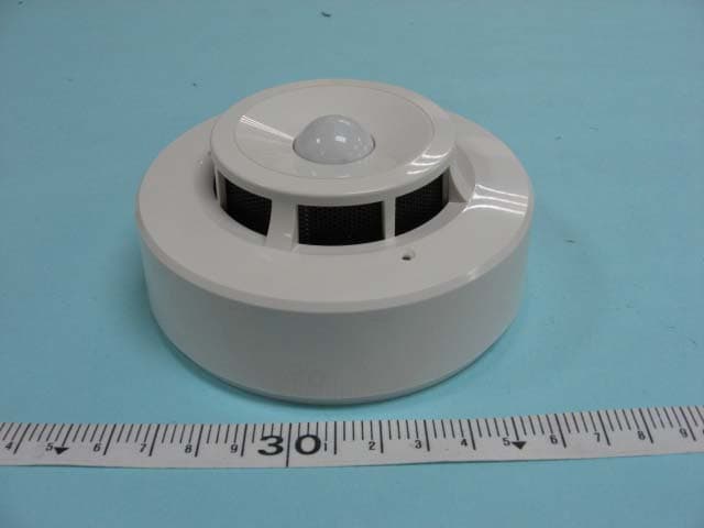
Jan 18, 2007Wireless PIR Detector
Equipment Class
DSC - Part 15 Security/Remote Control Transmitter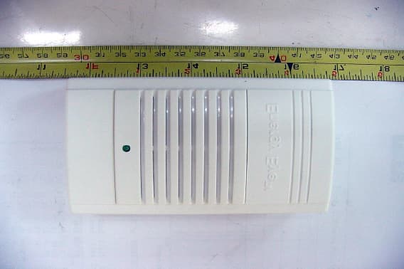
QBQENERGYEYERX01
May 07, 2002Brain Unit (Microprocessor and receiver)
Equipment Class
CYY - Communications Receiver used w/Pt 15 Transmitter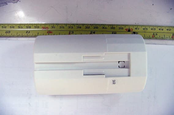
QBQENERGYEYEIR02
May 07, 2002Wireless PIR Detector
Equipment Class
DSC - Part 15 Security/Remote Control Transmitter