QCJRADEKLRadar Development Kit
Zebra Technologies Corporation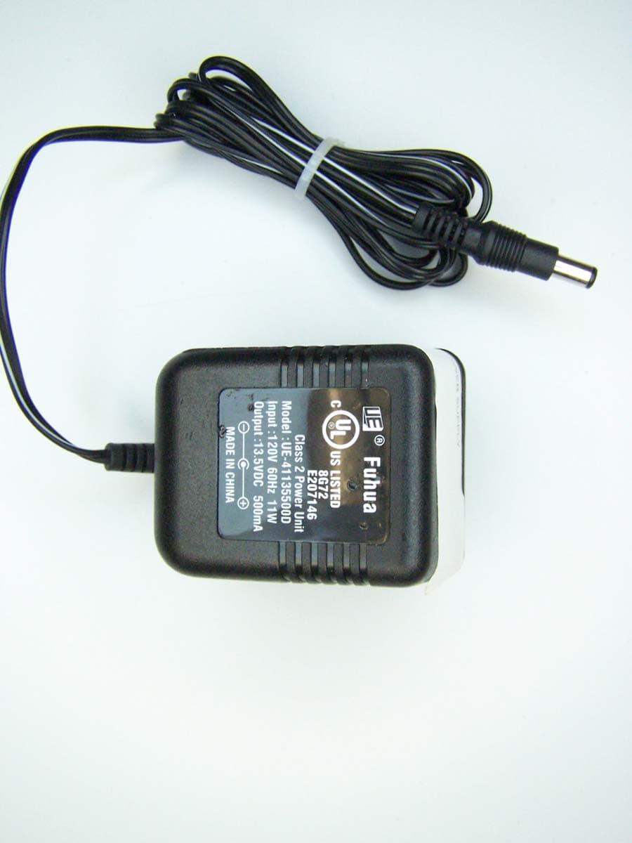
Click to zoom
Application Details
- Equipment Class
- WBT - Wideband Transmitter
- Date of Grant
- Oct 11, 2007
- Application Purpose
- Original Equipment
- Date of Application
- Aug 15, 2007
- Equipment Note
- Radar Development Kit
- Frequency Range
- 5997.00000000 - 7245.00000000
- Country
- United States
Documents & Files
Document Text
Text extracted from the exhibit documents filed with the FCC. Open a document above to read the original.
Users Manual
® MULTISPECTRAL SOLUTIONS, INC. ® RaDeKL Radar API for Windows Radar Developer’s Kit – Lite – Application Programming Interface Programmer's Guide Version 2.0 Revised: 05 OCT 07 © 2006 Multispectral Solutions, Inc. 20300 Century Boulevard Germantown, MD 20874-1132 Phone: (301) 528-1745 Fax: (301) 528-1749 Website: www.multispectral.com NOTE: The RaDeKL radar unit has been tested to comply with FCC Part 15, Subpart C for WBT devices. Changes or modifications to the radiating elements of RaDeKL not expressly approved by the party responsible for compliance could void the user’s authority to operate the equipment. NOTE: The RaDeKL radar unit has been tested and found to comply with the limits for a Class B digital device, pursuant to part 15 of the FCC Rules. These limits are designed to provide reasonable protection against harmful interference in a residential installation. This equipment generates, uses and can radiate radio frequency energy and, if not installed and used in accordance with the instructions, may cause harmful interference to radio communications. However, there is no guarantee that interference will not occur in a particular installation. If this equipment does cause harmful interference to radio or television reception, which can be determined by turning the equipment off and on, the user is encouraged to try to correct the interference by one or more of the following measures: —Reorient or relocate the receiving antenna. —Increase the separation between the equipment and receiver. —Connect the equipment into an outlet on a circuit different from that to which the receiver is connected. —Consult the dealer or an experienced radio/TV technician for help. RaDeKL Radar API Programmer’s Guide I © Multispectral Solutions, Inc. 2006 Table of Contents Part I: Welcome to the RaDeKL Radar API....................................................................1 Introduction .................................................................................................................................... 1 USB Driver Installation.................................................................................................................. 1 Programming Notes ...................................................................................................................... 3 Usage Warnings............................................................................................................................. 4 Part II: Status Formatting Functions .............................................................................5 RaDeKL_GetStatusText ................................................................................................................ 5 RaDeKL_GetAPIVersion................................................................................................................ 7 Part III: Radar Management Functions..........................................................................8 RaDeKL_ListRadars ...................................................................................................................... 8 RaDeKL_ListRadarsCleanup ...................................................................................................... 10 RaDeKL_OpenRadar ................................................................................................................... 11 RaDeKL_CloseRadar................................................................................................................... 12 RaDeKL_GetDeviceInfo............................................................................................................... 13 RaDeKL_ResetRadar................................................................................................................... 14 RaDeKL_FlushIO ......................................................................................................................... 15 Part IV: Radar Parameter Functions ............................................................................16 RaDeKL_SetThresholds.............................................................................................................. 16 RaDeKL_GetThresholds ............................................................................................................. 17 RaDeKL_SetTransmitAttenuation .............................................................................................. 18 RaDeKL_GetTransmitAttenuation ............................................................................................. 19 RaDeKL_SetReceiveAttenuation ............................................................................................... 20 RaDeKL_GetReceiveAttenuation ............................................................................................... 21 RaDeKL_SetRangeDelay............................................................................................................. 22 RaDeKL_GetRangeDelay ............................................................................................................23 RaDeKL_SetInterval .................................................................................................................... 24 RaDeKL_GetInterval .................................................................................................................... 25 RaDeKL_SimulatorMode............................................................................................................. 26 Part V: Radar Detection Functions ..............................................................................27 RaDeKL_DetectSingle ................................................................................................................. 27 RaDeKL_StartContinuousDetection .......................................................................................... 28 RaDeKL_StopContinuousDetection .......................................................................................... 30 RaDeK…
Text truncated - open the document above for the full version.
Users Manual
RaDeKL Radar ICD 107-201-001 ISSUE 2.10 © 2006 Multispectral Solutions, Inc. All rights reserved. Multispectral Solutions 20300 Century Blvd. Germantown, MD 20874 Phone 301-528-1745 FAX 301-528-1749 This document is Confidential and Proprietary and is for the use of Multispectral Solutions, Inc. personnel only, except to the extent that permission is expressly granted elsewhere. In any event, no part of this document may be reproduced or redistributed in any form without the express written consent of Multispectral Solutions, Inc. MULTISPECTAL SOLUTIONS, INC. PROPRIETARY AND CONFIDENTIAL 1 of 26 Radar Developer’s Kit – Lite (RaDeKL) Hardware Level Interface Control Document (ICD) Revision Number: 2.00 Revision Date: August 2007 Prepared by: Multispectral Solutions, Inc. 20300 Century Boulevard Germantown, MD 20874 RaDeKL Radar ICD 107-201-001 ISSUE 2.10 © 2006 Multispectral Solutions, Inc. All rights reserved. Multispectral Solutions 20300 Century Blvd. Germantown, MD 20874 Phone 301-528-1745 FAX 301-528-1749 This document is Confidential and Proprietary and is for the use of Multispectral Solutions, Inc. personnel only, except to the extent that permission is expressly granted elsewhere. In any event, no part of this document may be reproduced or redistributed in any form without the express written consent of Multispectral Solutions, Inc. MULTISPECTAL SOLUTIONS, INC. PROPRIETARY AND CONFIDENTIAL 2 of 26 REVISION HISTORY Issue No. Issue Date Originator Details of Change 1.00 August 10, 2006 David Wu Initial draft 2.00 August 1, 2007 Lester Foster Update for FCC Testing 2.10 October 5, 2007 Lester Foter Update for FCC Certification RaDeKL Radar ICD 107-201-001 ISSUE 2.10 © 2006 Multispectral Solutions, Inc. All rights reserved. Multispectral Solutions 20300 Century Blvd. Germantown, MD 20874 Phone 301-528-1745 FAX 301-528-1749 This document is Confidential and Proprietary and is for the use of Multispectral Solutions, Inc. personnel only, except to the extent that permission is expressly granted elsewhere. In any event, no part of this document may be reproduced or redistributed in any form without the express written consent of Multispectral Solutions, Inc. MULTISPECTAL SOLUTIONS, INC. PROPRIETARY AND CONFIDENTIAL 3 of 26 NOTE: The RaDeKL radar unit has been tested to comply with FCC Part 15, Subpart C for Wideband Transmitter (WBT) devices. Changes or modifications to the radiating elements of RaDeKL not expressly approved by the party responsible for compliance could void the user’s authority to operate the equipment. NOTE: The RaDeKL radar unit has been tested and found to comply with the limits for a Class B digital device, pursuant to part 15 of the FCC Rules. These limits are designed to provide reasonable protection against harmful interference in a residential installation. This equipment generates, uses and can radiate radio frequency energy and, if not installed and used in accordance with the instructions, may cause harmful interference to radio communications. However, there is no guarantee that interference will not occur in a particular installation. If this equipment does cause harmful interference to radio or television reception, which can be determined by turning the equipment off and on, the user is encouraged to try to correct the interference by one or more of the following measures: —Reorient or relocate the receiving antenna. —Increase the separation between the equipment and receiver. —Connect the equipment into an outlet on a circuit different from that to which the receiver is connected. —Consult the dealer or an experienced radio/TV technician for help. RaDeKL Radar ICD 107-201-001 ISSUE 2.10 MULTISPECTRAL SOLUTIONS, INC. PROPRIETARY AND CONFIDENTIAL 4 of 26 CONTENTS 1 INTRODUCTION ......................................................................................7 1.1 WBT DESCRIPTION......................................................................7 1.2 SYSTEM DESCRIPTION ...............................................................8 1.3 SYSTEM OPERATION.................................................................10 2 HARDWARE CONNECTIONS................................................................12 3 USB INTERFACE ...................................................................................13 3.1 RADAR INTERFACE COMMANDS .............................................13 3.1.1 LOW LEVEL COMMAND SYNTAX ...................................13 3.1.2 LOW LEVEL RESPONSE SYNTAX ..................................13 4 MEMORY MAP .......................................................................................15 RaDeKL Radar ICD 107-201-001 ISSUE 2.10 MULTISPECTRAL SOLUTIONS, INC. PROPRIETARY AND CONFIDENTIAL 5 of 26 LIST OF FIGURES FIGURE 1: MEASURED TIME AND FREQUENCY RESPONSES FROM MSSI C- BAND TRANSMITTER......................................................................................... 7 FIGURE 2: WBT RADAR SYSTEM BLOCK DIAGRAM 8 FIGURE 3: SURFACE-TO-SURFACE RADAR OPS WITH MULTIPATH 10 FIGURE 4: THE AFFECT OF MULTIPATH ON RADAR PERFORMANCE FOR A RADAR MOUNTED AT A TWO METER HEIGHT AND A TARGET AT ONE METER HEIGHT 11 RaDeKL Radar ICD 107-201-001 ISSUE 2.10 MULTISPECTRAL SOLUTIONS, INC. PROPRIETARY AND CONFIDENTIAL 6 of 26 LIST OF TABLES TABLE 1: WBT RADAR PERFORMANCE CHARACTERISTICS (30 MWATT VERSION) 9 TABLE 2 REGISTER MEMORY MAP.................................................................15 RaDeKL Radar ICD 107-201-001 ISSUE 2.10 MULTISPECTRAL SOLUTIONS, INC. PROPRIETARY AND CONFIDENTIAL 7 of 26 1 INTRODUCTION This Interface Control Document (ICD) provides information on the design and operation of Multispectral Solutions Inc.’s (MSSI’s) Wideband Transmitter (WBT) pulse Radar Developer’s Kit – Lite (RaDeKL) radar. The WBT pulse radar provides a very low radiated average power waveform in C-Band by using a low duty cycle, short pulse waveform. The radar was initially designed to detect the intrusion of small targets within a sec…
Text truncated - open the document above for the full version.
Users Manual
® MULTISPECTRAL SOLUTIONS, INC. ® Welcome to the RaDeKL Radar GUI Radar Developer’s Kit – Lite User's Guide And Help File Please scroll down Version 2.0 Revised: 05 OCT 07 © 2006 Multispectral Solutions, Inc. 20300 Century Boulevard Germantown, MD 20874-1132 Phone: (301) 528-1745 Fax: (301) 528-1749 Website: www.multispectral.com NOTE: The RaDeKL radar unit has been tested to comply with FCC Part 15, Subpart C for WBT devices. Changes or modifications to the radiating elements of RaDeKL not expressly approved by the party responsible for compliance could void the user’s authority to operate the equipment. NOTE: The RaDeKL radar unit has been tested and found to comply with the limits for a Class B digital device, pursuant to part 15 of the FCC Rules. These limits are designed to provide reasonable protection against harmful interference in a residential installation. This equipment generates, uses and can radiate radio frequency energy and, if not installed and used in accordance with the instructions, may cause harmful interference to radio communications. However, there is no guarantee that interference will not occur in a particular installation. If this equipment does cause harmful interference to radio or television reception, which can be determined by turning the equipment off and on, the user is encouraged to try to correct the interference by one or more of the following measures: —Reorient or relocate the receiving antenna. —Increase the separation between the equipment and receiver. —Connect the equipment into an outlet on a circuit different from that to which the receiver is connected. —Consult the dealer or an experienced radio/TV technician for help. RaDeKL Radar User’s Guide I © Multispectral Solutions, Inc. 2006 Table of Contents Part I: Welcome to the RaDeKL Radar GUI ...................................................................1 Introduction .................................................................................................................................... 1 Main Screen Layout....................................................................................................................... 1 Playback Screen Layout ............................................................................................................... 4 Part II: Usage ...................................................................................................................5 Setup ............................................................................................................................................... 5 Display Radar Data ........................................................................................................................ 5 File Playback .................................................................................................................................. 5 Part III: Appendix.............................................................................................................6 USB Driver Installation.................................................................................................................. 6 RaDeKL Radar User’s Guide 1 © Multispectral Solutions, Inc. 2006 Part I: Welcome to the RaDeKL Radar GUI Introduction The RaDeKL Radar GUI provides a simple-to-use interface to the Multispectral Solutions’ RaDeKL Radar device, allowing for the graphical display of radar data as well as the configuration of various operational parameters and settings as well as record/playback of radar data in real-time. This document familiarizes the reader with the features of the RaDeKL Radar application. Note: Before the RaDeKL Radar unit can be used, the appropriate USB driver must be installed. Refer to the appendix at the bottom for instructions. Main Screen Layout 1 2 3 4 5 6 7 8 9 10 11 12 RaDeKL Radar User’s Guide 2 © Multispectral Solutions, Inc. 2006 1. Display Selection Select the type of graphical display: a. Amplitude: An X-Y graph with range bin numbers (approx. in feet) across the X-axis and radar return value across the Y-axis. b. Waterfall: Continuous time display with range bin numbers (approx. in feet) across the X-axis and a color-coded radar return values flowing down the top in continuous mode. 2. Filter Settings These filter settings are applied after the data is returned from the radar: a. Off: no filter is applied. b. Averaging: Autoregressive smoothing filter (low-pass) over time. Enter a coefficient between 0.000 and 1.000 and click “Apply” to smooth the radar return value over time. This will make abrupt changes appear more smooth c. MTI: Autoregressive background subtraction filter (high-pass) over time. Enter a coefficient between 0.000 and 1.000 and click “Apply” to highlight changes from the previous sample over time. This filter makes it easier to detect sudden changes in the field of the radar. 3. Clear Display Clicking this button clears the graphical display area. 4. Display Area The graphical display area. This is where the radar data is displayed in graphical form, either as an amplitude or waterfall chart. 5. Status Line The status line shows the status of the radar or the last action requested, along with an icon indicating the run status of the radar or playback file. 6. Range Bins The X-axis of the display area labels the range bin (1-256) displayed horizontally. Each range bin represents a 1-nanosecond interval, which is roughly equivalent to 1 foot. The exact range bin intervals are 11.8 inches (30.0 cm) per range bin. 7. Zoom Buttons and Scrollbar Zoom horizontally up to 8 times. Once the zoom setting is greater than 1, use the scrollbar to move horizontally over the entire range of range bins. Note: If your PC is slower than 800 MHz or is very busy with other tasks, using a zoom setting of 8 and a Sample Interval of 50 ms (in continuous mode) may result in display lag or even an I/O error, since the application will no longer be able to keep up with the incoming data…
Text truncated - open the document above for the full version.
External Photos
Photograph 1. DC Power Connector Photograph 2. Front 1 Photograph 3. Power Supply 1 Photograph 4. Power Supply 2 Photograph 5. Rear of Unit Photograph 6. Top
ID Label/Location Info
Figure 1. Label Location
Internal Photos
Photograph 1. View of Internal Components Photograph 2. Antenna Back Photograph 3. Antenna Front Photograph 4. View of Internal Components Photograph 5. View of Internal Components Photograph 6. View of Internal Components Photograph 7. View of Internal Components Photograph 8. View of Internal Components Photograph 9. View of Internal Components Photograph 10. View of Internal Components Photograph 11. View of Internal Components Photograph 12. View of Internal Components
Operational Description
RaDeKL Antenna Data The Radar Developer’s Kit – Lite (RaDeKL) (Figure 1) utilizes two identical directional antennas for the transmitter and the receiver. RaDeKL antenna consists of four elements in a two by two patch array. The antenna peak gain is approximately 12 dBi, and the Fields of View (FOVs) (at the -3 dB from peak) for both azimuth and elevation are approximately 45 x 45 degrees. The orientation of the antenna shown Figure 1 has electrical field plane polarity in the horizontal direction. The physical dimensions of each antenna are 63 x 63 x 8 millimeters including radome and excluding the SMA connector on the back. Figure 1. Radar Developer’s Kit – Lite (RaDeKL) Unit with Identical Dual Antennas, One for Transmit and the Other for Receive The Figure 2 shows the gain pattern for the lower, center and high frequency of the RaDeKL Ultra Wideband (UWB) channel. The Voltage Standing Wave Resonance (VSWR) across the UWB channel has an average value of 1.5. The antenna back-plate is mounted and grounded to the chassis faceplate. For the production RaDeKL unit, Multispectral Solutions, Inc. will mount the antennas and RaDeKL chassis faceplate with tamperproof screws that require a special tool for fastening. E-Plane -35 -30 -25 -20 -15 -10 -5 0 5 10 15 -180 -160 -140 -120 -100 -80-60-40-20020406080100120140 160180 Rotation Angle Gain (dBi) 6.15 GHz E-Plane -35 -30 -25 -20 -15 -10 -5 0 5 10 15 -180 -160 -140 -120 -100 -80-60-40-20020406080100120140160180 Rotation Angle Gain (dBi) 6.35 GHz E-Plane -35 -30 -25 -20 -15 -10 -5 0 5 10 15 -180 -160 -140 -120 -100 -80-60-40-20020406080100120 140160180 Rotation Angle Gain (dBi) 6.55 GHz H-Plane -35 -30 -25 -20 -15 -10 -5 0 5 10 15 -180 -160 -140 -120 -100 -80-60-40-20020406080100120140 160180 Rotation Angle G a in (d B i) 6.15 GHz H-Plane -35 -30 -25 -20 -15 -10 -5 0 5 10 15 -180 -160 -140 -120 -100 -80-60-40-20020406080100120140 160180 Rotation Angle Gain (dBi) 6.35 GHz H-Plane -35 -30 -25 -20 -15 -10 -5 0 5 10 15 -180 -160 -140 -120 -100 -80-60-40-20020406080100120140 160180 Rotation Angle Gain (dBi) 6.55 GHz Figure 2. RaDeKL Antenna Gain Patterns for Electric and Magnetic Planes for Lower, Center and Higher UWB Channel Frequencies
Operational Description
A Tradition of Excellence in Innovation MULTISPECTRAL SOLUTIONS, INC. For more information, contact Dr. Lester Foster at (301) 528 – 1745 or [email protected] Radar Developer’s Kit – Lite (RaDeKL) Description The Radar Developer’s Kit Lite (RaDeKL) is the next generation design of Multispectral Solutions, Inc.’s (MSSI’s) Ultra Wideband pulse radar technology. The radar is compliant to Federal Communications Commission (FCC) Part 15.250 for unlicensed operation. RaDeKL allows government, industry and academia to evaluate the benefits of MSSI’s UWB radar technology to detect the presence of targets with precision range. The radar output provides 256 range bins with 30 cm (~1 foot) range resolution and 5-bit/32 levels of return signal power amplitude resolution. Detection ranges to targets depend upon radar cross section of target. Adult human detection range extent is 60 feet nominal. The kit includes the radar hardware, supporting software drivers and user interface application for simple radar operation and control. The application allows viewing of radar return data and data logging for additional return signal post-processing. Specifications Radio Technology Ultra WideBand (UWB) Frequency of Operation 6.1 – 6.6 GHz (-3 dB) Transmitter Output Power FCC Part 15.250 Compliant, variable to 25 dB lower Physical Dimensions 150 x 83 x 62 (including radome height) mm, 490 grams Receiver Antenna 12 dBi Gain with 45 x 45 degree Field of View Receiver Sensitivity -75 dB at 10 dB S/N Receiver Dynamic Range 40 dB above minimum detectable signal Range Resolution 30 cm (approximately 12 inches) Return Amplitude Resolution 32 levels, (5 bits) Number of Range Bins 256 per sample Range Extent up to 345.6 meters Operating Voltage 12 V DC, 110 V power supply provided Current Consumption 100 ma Temperature Range 0 to 50 deg C Frequency of update rate Selectable single return by command up to 20 Hz streaming Interface USB 2.0 compliant Driver and Application OS Windows 2000 ______________________________________________________________________________ A Tradition of Excellence in Innovation MULTISPECTRAL SOLUTIONS, INC. For more information, contact Dr. Lester Foster at (301) 528 – 1745 or [email protected] System Operation The radar system is composed of three major subsystems. The first is the return signal processing and user data interface card. This circuit card controls the radar Ultra Wideband (UWB) pulse transmissions and the high speed return signal processing. The second component is the UWB RF Front end circuit card which provides a short pulse transmissions spanning the frequency range from 6.1 to 6.6 GHz and the receiver radio frequency front end which conditions the radar signal for return processing. The last subsystem is the two antenna array providing an antenna each for the transmitter and receiver minimizing the insertion loss of a switch or circulator and maximizing the RF isolation between the transmitter and receiver circuitry. The radar sensor is grounded to the power supply ground. All components within the unit are grounded to the power supply including the antennas. Also, the antennas are grounded to the chassis since they are mounted to the chassis with screws that complete the connection between the antenna ground plane and the chassis. The radar is controlled by a series of commands through the Universal Serial Bus (USB) electrical and data interface. The RaDeKL Application Program Interface (API) describes the different serial communication command definitions to set the radar transmitter and receiver processor sensitivity settings, and how to control sampling of the environment from a single sensor snapshot to streaming data at up to a 20 Hz rate. MSSI’s patented UWB radar operates by transmitting and receiver processing individual UWB pulses. Upon initiating a UWB pulse transmission, the digital processor initiates a timer/counter. The receiver RF front end filters and amplifies the return, passing the signal to the diode detector. After a measured time has elapsed corresponding to the minimum range to initiate detection, the diode detector video output is passed to a bank of comparators, each comparing the return to a reference voltage or threshold. The comparators cycle between voltage high or zero depending on whether the reference voltage has been exceeded by the video output. The receiver processor samples the comparator outputs with two nanosecond time steps which correspond to one foot radar range bins. This receiver processing technique permits a fast and simple analog- to-digital conversion of the return signal amplitude over the entire range space in one transmitted pulse. Since the receiver measures return signal power amplitude, the receiver does not depend on relative motion of the target but rather only its presence. As a consequence, the detector is capable of detecting very slow moving targets. The above process is repeated and signal magnitude levels are chosen based upon their exceeding threshold 13 out of 16 times. By re- sampling the radar field of view using 32 user defined threshold settings, the radar can provide return amplitude information to meet the needs of the user. Once the radar return signal has been characterized, the data is passed through the USB interface utilizing the USB chip manufacturer’s drivers and following the data protocols defined in the RaDeKL API. A RaDeKL graphical user interface software program was developed for Windows 2000 computers to provide an intuitive user interface for control, display and data collection of the radar operation.
Parts List/Tune Up Info
MSSI Proprietary Schematic Number: Parts obsoleted: 0 ITEM QTY REFDES 11 A1 22 C1,C2 33 C10,C11,C12 41 C13 52 C14,C17 62 C15,C43 72 C16,C42 82 C18,C37 95 C19,C20,C23,C51,C53 102 C21,C22 113 C24,C52,C54 122 C26,C38 131 C27 141 C28 156 C29,C30,C33,C34,C36, C47 161 C3 173 C31,C35,C46 181 C32 192 C39,C40 204 C4,C5,C6,C7 211 C41 224 C56,C57,C8,C9 231 D2 242 FL1,FL2 252 HW1,HW11 262 HW10,HW9 271 HW12 283 HW5,HW6,HW7 291 HW8 302 J1,J5 311 J2 322 J3,J6 332 L1,L2 343 L3,L4,L5 351 Q1 361 Q2 371 Q3 382 R1,R20 391 R10 401 R11 413 R12,R29,R32 428 R13,R14,R15,R18,R19, R35,R36,R42 432 R16,R17 441 R2 451 R21 462 R22,R23 474 R25,R3,R5,R7 483 R26,R27,R28 492 R30,R31 501 R37 511 R38 522 R39,R40 532 R4,R6 541 R41 551 R46 561 R47 571 R8 581 R9 592 TP1,TP2 602 U1,U2 612 U11,U12 621 U15 631 U3 641 U4 651 U5 661 U6 672 W1,W2 107-200-001-rb2 Parts without RoHS: 7Error: RoHS compliance n o DescriptionMFGR_PART_NUMBER C-BAND 30MW TX MODULE126-209-003 CAP, CHIP, SMD251R14S1R0BV4 CAP, CHIP, SMDECJ-2YB1E224K CAP, CHIP, SMDECJ-2FB0J475M CAP, CHIP, SMDECJ-0EB1E102K CAP, CHIP, SMDECJ-0EC1H101J CAP, CHIP, SMDECJ-0EB0J105M CAP, CHIP, SMDECJ-0EF1C104Z CAP, CHIP, SMDECJ-2VC1H102J CAP, CHIP, SMDECJ-2VC1H100D CAP, CHIP, SMDECJ-2VF1C105Z CAP, CHIP, SMDECJ-0EB1C103K CAP, CHIP, SMD251R14S2R4BV4 CAP, CHIP, SMDECJ-1VB1H393K CAP, CHIP, SMDECJ-1VB1C104K CAP, CHIP, SMD251R14S0R3AV4 CAP, CHIP, SMDECJ-1VC1H471J CAP, CHIP, SMDECJ-1VC1H100D CAP, CHIP, SMD251R14S1R5BV4 CAP, CHIP, SMD251R14S1R8BV4 CAP, CHIP, SMD500R07S1R6BV4 TAJ CAP, SMDTAJB476K006R TUNNEL, MICROWAVEMP1X8016 BANDPASS FILTER, 6.35GHZ126-205-000 SHIELD, CONNECTOR COVER, SMA (L350MILS X W154MILS X H140MILS)701-123-000 TEFLON TUBING, 95MIL INSIDE DIA, (3.5 INCHES)TFT-200-11 SHIELD, RECTANGULAR, W/TABS (L990MILS X W400MILS X H150MILS)126-103-000 SHIELD, RECTANGLE (L1100MILS X W800MILS X H200MILS)701-130-000 SHIELD, RECTANGULAR, W/TABS (L485MILS X W380MILS X H150MILS)126-104-000 PLUG ASSY STR SOLDER SMA RG405142-0693-001 40 PIN DOUBLE ROW .05" FEMALE SMTSFM-120-02-S-D-LC END LAUNCH TERMINATION .062 PCB, SEMI-RIGID .086142-0093-801 INDUCTOR, CHIP, SMD0805CS-121XJL FERRITE, CHIP, SMDLI0805H151R-10 DUAL N/P CHAN HEXFET POWER MOSFETIRF7509 PNPMMBT3906 NPN, LOW CURRENTAT-30533-BLKG RES, CHIP, SMDERJ-2GEJ100X ATT, CHIP, SMDA-0805-C-07DB RES, CHIP, SMDERJ-6GEYJ100V RES, CHIP, SMDERJ-3GEYJ101V RES, CHIP, SMDERJ-2GEJ101X RES, CHIP, SMDERJ-6ENF4751V RES, CHIP, SMDERJ-2GEJ151X RES, CHIP, SMDERJ-6GEYJ201V RES, CHIP, SMDERJ-6GEYJ103V RES, CHIP, SMDERJ-2GEJ103X RES, CHIP, SMDERJ-3GEY0R00V RES, CHIP, SMDERJ-6GEYJ102V RES, CHIP, SMDERJ-3GEYJ512V RES, CHIP, SMDERJ-3GEYJ152V RES, CHIP, SMDERJ-3GEYJ122V RES, CHIP, SMDERJ-2GEJ180X RES, CHIP, SMDERA-V33J681V RES, CHIP, SMDERJ-3GEYJ104V RES, CHIP, SMDERJ-3GEYJ513V RES, CHIP, SMDERJ-2GEJ330X RES, CHIP, SMDERJ-2GE0R00X PC TEST POINT, MINIATURE, SMT5015 BIPOLAR CASCADABLE AMPMSA-0611-BLKG LOW NOISE GAAS AMPMGA-86576-STRG HIGH-OUTPUT-DRIVE, 10MHZ, 10V/μS, RAIL-TO-RAIL I/O OP AMPMAX4230AXK+ ULTRA LOW NOISE PSEUDOMORPHIC HEMTATF-36077-STR 1900 MHZ SI RFIC AMPUPC2749TB-A LOW-NOISE, REGULATED, -2V GAASFET BIASMAX840ISA 6-BIT DIGITAL POSITIVE CONTROL ATTENUATOR, 0.5DB STEPHMC425LP3 SEMI-RIGID COAX CABLE .086 (4.5 INCHES)1671A-100-TIN 11/16/2006 ot met. MFGR VALUEPACKAGE MSSI126-209-003_MSSI JOHANSON TECHNOLOGY1.0PFCC0603_JOTC PANASONIC - ECG0.22UFCC0805_PANA PANASONIC - ECG4.7UFCC0805_PANA PANASONIC - ECG1000PF CC0402_PANA PANASONIC - ECG100PFCC0402_PANA PANASONIC - ECG1.0UFCC0402_PANA PANASONIC - ECG0.1UFCC0402_PA…
Text truncated - open the document above for the full version.
Contact Information
Applicant
Qianlin Zhou(Advanced Regulatory Specialist)
Technical Contact
MET Laboratories, Inc.Jeffrey Hazen
[email protected]410-354-3300
914 W. Patapsco Ave. · Baltimore, Maryland · United States
Non-Technical Contact
JenniferSanchez
[email protected]410-354-3300
Test Firm
MET Laboratories, Inc.Kevin Mehaffey
Technical Specifications
| # | Rule Parts | Frequency Range | Power Output |
|---|---|---|---|
| 1 | 15.250 | 6.00 GHz - 7.25 GHz | - |
Other Applications from Zebra Technologies Corporation
QCJSAFR218
Jun 03, 2008Wideband RFID/RTLS Tag
Equipment Class
WBT - Wideband Transmitter
QCJPAL6511X1
Oct 24, 2006RF Tag
Equipment Class
DXX - Part 15 Low Power Communication Device Transmitter
QCJPAL1X1
Dec 19, 2004RF Tag
Equipment Class
UWB - Ultra Wideband Transmitter
QCJPALBDG
Nov 02, 2004RF Tag
Equipment Class
UWB - Ultra Wideband Transmitter
QCJPAL650
Jul 30, 2003Short Pulse Precision Asset Location System
Equipment Class
UWB - Ultra Wideband Transmitter