QCZSECUMANVoice Dialer
VESSCO, inc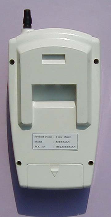
Click to zoom
Application Details
- Equipment Class
- CYY - Communications Receiver used w/Pt 15 Transmitter
- Date of Grant
- Nov 11, 2002
- Application Purpose
- Original Equipment
- Date of Application
- Nov 11, 2002
- Equipment Note
- Voice Dialer
- Frequency Range
- 447.35000000 - 447.35000000
- Company
- VESSCO, inc
- Country
- South Korea
Documents & Files
Document Text
Text extracted from the exhibit documents filed with the FCC. Open a document above to read the original.
Users Manual
– “” “” “” “” “” “” “” “” “” “”“” “” “”“” – “” “” “” “” “” “” “” “” “” “” “” “” “” “” “” “” “” “” “” “” “” “” “” – ’
Block Diagram
5 5 4 4 3 3 2 2 1 1 DD CC BB AA <RX BOARD BLOCK DIAGRAM> BPF RF AMP 10.7MHz10.245MHz IF AMP 3rd OVER TONE RF AMP OSC 2nd MIXER 3rd FREQUENCY MULTIPLIER 1st MIXER OP AMP CONTROL BOARD RX DATA ANTENNA
External Photos
(External Photos)
ID Label/Location Info
ID Label
Internal Photos
(Internal Photos)
Test Report
KTL Korea Testing Laboratory Page 1 of 12 TEST REPORT This test report only responds to the tested sample and shall not be reproduced except in full without written approval of the Korea Testing Laboratory. Tested and reported by Reviewed by Jeong-Min Kim , Senior Engineer Hee-Soo Kim , Telecommunication Team Manager KOREA TESTING LABORATORY FG101-01-02-00 222-13, Guro-Dong Guro-Gu Seoul Korea 152-053 http://www.ktl.re.kr Ref. Report No. 02-341-013-01 Name and address of the applicant VESSCO Inc. 506, Jungwoo APT. Factory, 223-271, Suknam-dong, Seo-gu, Inchon-shi, 404-824,Korea Standard / Test regulation FCC Part 15, Subpart B Test result Pass Incoming date : April 19, 2002 Test item(s) ; Communication Receiver used with Part 15 Tx (Voice Dialer) Model/type ref. ; Secuman Manufacturer ; VESSCO Inc. Additional information ; -Required Authorization : Certification -FCC ID. : QCZSECUMAN -Note : Test report(Certification) of Transmitter portions of this System are issued on Ref. Report No. 02-341-013-02 and 02-341-013-03 respectively. Test date : October 16, 2002 Issue date : October 21, 2002 Ref. Report No. 02 - 341 – 013 - 01 Page 2 of 12 Korea Testing Laboratory Telecommunication Team 222-13, Guro3-dong, Guro-gu, Seoul Korea 152-848 TABLE OF CONTENTS I. GENERAL INFORMATION 3 1. Grantee’s Name and Mailing Address 2. Manufacturer's Name and Mailing Address 3. Equipment Descriptions 4. Rules and Regulations 5. Measuring Procedure 6. Place of Measurement 7. Date of Measurement . GENERAL REQUIREMENTS OF THE EUT 4 1. Labeling Requirement (Section 15.19) 2. Information to User (Sections 15.21) 3. Special Accessories (Section 15.27) . CONDUCTED EMISSION MEASUREMENT (Section 15.107) 5 1. Test Procedure 2. Photograph for the test configuration 3. Sample Calculation 4. Measurement Data . RADIATED EMISSION MEASUREMENT (Section 15.109) 9 1. Test Procedure 2. Photograph for the test configuration 3. Sample Calculation 4. Measurement Data . TEST EQUIPMENTS USED FOR MEASUREMENT 12 Ref. Report No. 02 - 341 – 013 - 01 Page 3 of 12 Korea Testing Laboratory Telecommunication Team 222-13, Guro3-dong, Guro-gu, Seoul Korea 152-848 . GENERAL INFORMATION 1. Grantee’s Name and : VESSCO Inc. Mailing Address 506 Jungwoo APT. Factory, 223-271, Suknam-dong, Seo-gu, Inchon, 404-824, Korea 2. Manufacturer's Name and : VESSCO Inc. Mailing Address 506 Jungwoo APT. Factory, 223-271, Suknam-dong, Seo-gu, Inchon, 404-824, Korea 3. Equipment Descriptions 3.1 Operating Frequency : 447.35 MHz 3.2 Detect Method : Superheterodyne Detector 3.3 Local Oscillator : Local Osc. Frequency = Operating Frequency – 10.7 MHz (IF) 3.4 Power Supply : DC 12 V Adapter or DC 9V Battery 4. Rules and Regulations : FCC Part 15, Subpart B 5. Measuring Procedure : ANSI C63.4-2001 6. Place of Measurement : Absorber-lined Room (KTL) 7. Date of Measurement 7.1 Conducted Emission : October 16, 2002 7.2 Radiated Emission : October 15, 2002 Ref. Report No. 02 - 341 – 013 - 01 Page 4 of 12 Korea Testing Laboratory Telecommunication Team 222-13, Guro3-dong, Guro-gu, Seoul Korea 152-848 . GENERAL REQUIREMENTS OF THE EUT 1. Labeling Requirement (Section 15.19) This device complies with Part 15 of the FCC Rules. Operation is subject to the following two conditions: (1) this device may not cause harmful interface, and (2) this device must accept any interference received, including interference that may cause undesired operation. 1.1 Location of Label : User’s Guide Manual 1.2 How Applied : Printed 2. Information to User (Section 15.21) The following or similar statements were provided in the manual for user instruction. Please refer page 11 of the attached manual for details. CAUTION : Any changes or modifications in construction of this device which are not expressly approved by the party responsible for compliance could void the user's authority to operate the equipment. 3. Special Accessories (Section 15.27) 3.1 Were the special Accessories provided? [ ] yes, [ x ] no 3.2 If yes, details for the special accessories are as follows : 3.3 If yes, were the appropriate instructions provided on the first page of the text concerned with the device? [ ] yes, [ ] no 3.4 Are these accessories provided of the type which can be readily obtained from multiple retail outlets ? [ ] yes, [ ] no And therefore does the manual specify what additional components or accessories are required to used in order to comply with the Rules? [ ] yes, [ ] no Ref. Report No. 02 - 341 – 013 - 01 Page 5 of 12 Korea Testing Laboratory Telecommunication Team 222-13, Guro3-dong, Guro-gu, Seoul Korea 152-848 . CONDUCTED EMISSION MEASUREMENT (Section 15.107) 1. Test Procedure Conducted emission measurements on the EUT were performed by "AC Power Line Conducted Emissions Testing" procedure as per ANSI C63.4. The EUT was set up on a wooden table 0.8 meters height, 1.0 by 1.5 meters in size, placed in the shielded enclosed with a side of wall of which constituted a vertical conducting surface of 2.2 m x 3.1 m in size to maintain 40 cm from the rear of EUT LISN(Line Impedance Stabilization Network, EMCO, 3825/2, 50 ohm / 50 μH) was installed and electrically boned to the conducting ground plane. The EUT was connected to the LISN. One of two 50 ohm output terminals of the LISN was connected to the EMI Receiver(ROHDE & SCHWARZ, ESI7, 20 Hz to 7 GHz) and the other was terminated in 50 ohms. Measurements were again performed after interchanging such a connection oppositely. The frequency range from 150 kHz to 30 MHz was examined and the remarkable frequencies were measured with Quasi-peak and Average values using the EMI receiver instrument (ROHDE & SCHWARZ, ESI7, 20 Hz to 7 GHz ; Detector Function ; CISPR Quasi-Peak & Average). The 6 dB bandwidth of the Receiver was set to 9 kHz The position of connecting cables of the EUT was changed to find the worst case configuration during measurements. The maximum emission level from the EUT occurred in such configuration as shown in the following photogra…
Text truncated - open the document above for the full version.
Test Setup Photos
Ref. Report No. 02 - 341 – 013 - 01 Page 7 of 12 Korea Testing Laboratory Telecommunication Team 222-13, Guro3-dong, Guro-gu, Seoul Korea 152-848 2. Photograph for the test configuration 3. Sample Calculation The emission level measured in decibels above one microvolt (dB) was converted into microvolt () as shown in following sample calculation. For example : Measured Value at 0.382 MHz 19.3 dB @ average mode + Cable Losses * 0.0 dB = Conducted Emission 19.3 dB ( = 9.2 ) * In case of RG214/RF cable 15 Ft, the loss is about 0.17 dB at the frequency of 30 MHz which is negligible.
Contact Information
Applicant
heejin lee(voice dialer)
Test Firm
Korea Testing LaboratoryJeong-Min Kim
Technical Specifications
| # | Rule Parts | Frequency Range | Power Output |
|---|---|---|---|
| 1 | 15B | 447.35 MHz - 447.35 MHz | - |
Other Applications from VESSCO, inc
QCZPRIS-770F
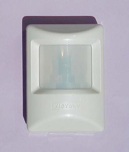
Nov 11, 2002Voice Dialer ( PIR Detector )
Equipment Class
DSC - Part 15 Security/Remote Control Transmitter
QCZTX-300F
Nov 11, 2002Voice Dialer ( Remote Controller )
Equipment Class
DSC - Part 15 Security/Remote Control Transmitter