FCCID.CO- FCC ID Database
HomeCompaniesEquipment ClassesSearch

© 2026 FCC ID Database. All rights reserved.

AboutContactData sourced from FCC public records
  1. Home/
  2. Corinex Global, a.s./
  3. QD9POWERNET-PCI

QD9POWERNET-PCIPowerline Telecommunication Modem for PCI slot

Corinex Global, a.s.
Powerline Telecommunication Modem for PCI slot - FCC ID QD9POWERNET-PCI - Corinex Global, a.s.
Click to zoom

Application Details

Equipment Class
JBP - Part 15 Class B Computing Device Peripheral
Date of Grant
May 22, 2002
Application Purpose
Original Equipment
Date of Application
May 22, 2002
Equipment Note
Powerline Telecommunication Modem for PCI slot
Company
Corinex Global, a.s.
Country
Slovak Republic

Documents & Files

Select a file to view

Users Manual

↗

Block Diagram

↗

Cover Letter(s)

↗

External Photos

↗

ID Label/Location Info

↗

Internal Photos

↗

Operational Description

↗

Schematics

↗

Test Report

↗

Test Setup Photos

↗

Document Text

Text extracted from the exhibit documents filed with the FCC. Open a document above to read the original.

Users Manual

C o r i n e x P o w e r N e t P C I C a r d Corinex PowerNet PCI Card Owner ́s Manual Model: CorinexPowerNetPCICard Manufacturer: CorinexGlobalCorp. #3081168HamiltonStreet VancouverB.C. V6B2S2Canada ThisdevicecomplieswithPart15rules.Operationissubjecttothefollowingtwo conditions: 1)thisdevicemaynotcauseharmfulinterference,and 2)thisdevicemustacceptanyinterferencereceived,includinginterferencethat maycauseundesiredoperation. ThisequipmenthasbeentestedandfoundtocomplywiththelimitsofaClassB digitaldevice,pursuanttoPart15oftheFCCRules. . Signature:.............................Place/Date:................. Printedname:..........................Position/Title:............. 2002 PeterSobotka CEO FCCID:QD9POWERNET-PCI DeclarationofConformity User Warning! Any changes of modification to said product not expressly approved by Corinex could void the user’s authority to operate the equipment. Model:CorinexPowerNetPCICard Manufactuter: CorinexGlobalCorp. #3081168HamiltonStreet VancouverB.C. V6B2S2Canada DirectiveswhichConformityisDeclared: EMC:89/336/EWG LVD:73/23/EEC 93/68/EEC StandardswhichConformityisDeclared: EN55022 EN55024 EN61000-3-2/A14 EN61000-3-3 EN60950 Theundersignedherebydeclarestheabovespecifiedequipmentconforms totheabovedirectivesandstandards. Signature:.............................Place/Date:................. Printedname:..........................Position/Title:............. PeterSobotka 2002 CEO DeclarationofConformity Contents 11..11OOvveerrvviieeww 5 C o r i n e x P o w e r n e t P C I C a r d • O w n e r ‘ r M a n u a l This Owner’s Manual, as well as the software described in it, is furnished under license and may be used or copied only in accordance with the terms and conditions of the license. The content of this manual is furnished for informational use only, it is subject to change without notice, and it does not represent a commitment on the part of Corinex Global Corp. Corinex Global Corp. assumes no responsibility or liability for any errors or inaccuracies that may appear in this book. It is our policy to enhance our products as new technologies, hardware components, software and firmware become available; therefore, the information contained in this document is subject to change without notice. You can download all CX software free updates from www.corinex.com . Some features, functions, and operations described in this manual may not be included and sold in certain countries due to government regulations or marketing policies. The use of the product or its features described in this document may be restricted or regulated by law in some countries. If you are unsure which restrictions or regulations apply, you should consult your local authorities. Published by: Corinex Global Corp. 33076– 1583 Marine Drive West Vancouver, B.C., V7V 1HO Canada Tel: (604) 692 0520 Fax: (604) 692 0555 Corinex is a registered trademark of Corinex Global Corp. Microsoft, MS-DOS, MS, Windows, Windows NT are either registered trademarks or trademarks of Microsoft Corporation in the U.S.A. and/or other countries. All products or company names mentioned herein may be the trademarks of their respective owners. Copyright (c) 2001-2002 by Corinex Global Corp. 11..11OOvveerrvviieeww 7 C o r i n e x P o w e r n e t P C I C a r d • O w n e r ‘ r M a n u a l Contents 1.Introduction.......................................................................... 9 1.1Overview.................................................................................. 9 1.2About this Manual.................................................................... 9 2.Installation Guide................................................................. 10 2.1Installing the Card in your Computer......................................... 10 2.2Driver Installation..................................................................... 10 3.User‘s Guide.......................................................................... 21 3.1Corinex PowerNet PCI Card....................................................... 21 3.2FAQ......................................................................................... 22 Contents 11IInnttrroodduuccttiioonn 11..11OOvveerrvviieeww 9 C o r i n e x P o w e r n e t P C I C a r d • O w n e r ‘ r M a n u a l 11Introduction 1.1Overview Corinex PowerNet PCI Card use 110V/220V powerline as a medium for communication. After successsful instalation, indoor powerline network behaves as traditional LAN (Local Area Network). Corinex PowerNet PCI Card supports 14 Mbps-network speed. The product keeps network maintenance cost low and eliminates usagebarriers while there is no need for additional wireing The Product is a higly integrated and requires no glue logic or external memory. It includes an interface for a boot ROM and can be used in diskless workstations, providing maximum network security and user friendly management features. 1.2About this Manual This Owner‘s Manual is intended to provide sufficient information to help you understand successfully install the Corinex PowerNet PCI Card products to meet your networking needs. With the information in this guide, you should be able to: ?Analyze your network needs... ?Plan the configuration of Corinex PowerNet PCI Card options... ?Install and configure your Corinex PowerNet PCI Card according to your plan... ?Verify and optimize your Corinex PowerNet PCI Card performance... 1 22InstallationInstallationGuide 22..11IInnssttaalllliinnggtheCardinyourComputer 22Installation Guide 2.1Installing the Card in your Computer To insert the Corinex PowerNet PCI Card into your computer, follow the steps listed bellow: 1.Turn off the computer and remove its cover. 2.Insert the Corinex PowerNet PCI Card into a PCI slot. 3.Secure the Corinex PowerNet PCI Card to the rear of the computer chassis and put back the computer cover. 4.Connect PCI outlet to PCI card. 5.Put PCI outlet socket to power line outlet. 6.Turn on the computer. 2.2Driver Installation Use drivers supplied by th…

Text truncated - open the document above for the full version.

Block Diagram

PCI CLOCK 33MHz MII MII TX CLOCK 25MHz PHY RTL8130 INT5130 PCI BUS 20Mhz 100MHz MAC BP AGC DAC ADC INT1000 PCI CARD PCI Outlet 8 `` Activity LED Colising LED Link LED 12V12V 12V12V BP 12V 12V 12V 12V FUSE 630mA RX CLOCK 25MHz DAC CLOCK 50MHz TX Enable TX Enable Y type 10p 4-21MHz BP 4-21MHz 4-21MHz 12V SAC 5.0 ERZ-VQ7D241 L N FUSE 630mA G=1 G=2

Cover Letter(s)

Coverletter: Corinex Global a.s. wants to get the FCC-Certification for the following product: Corinex PowerNet PCI The unit will get the following FCC-ID: QD9 POWERNET-PCI List of documents:: ExhibitThemaFile Exhibit 01 Label and placementFoto-plug.jpg Exhibit 02 Not needed-------------------- Exhibit 03 External Photos02-136_outside_fotos.pdf Exhibit 04 Block Diagramsblock.pdf Exhibit 05 Schematic Diagramspcisch.pdf Exhibit 06 Testreportreport02-136.pdf Exhibit 07 Test Set-up Photos02-136_test_setup_fotos.pdf Exhibit 08 User ManualCorinex_Powernet_PCI_Manual.pdf Exhibit 09 Internal Photos02-136_inside_fotos.pdf Exhibit 10 Not needed-------------------- Exhibit 11 Not needed-------------------- Exhibit 12 Operational Description OPERAT_final.doc Exhibit 13 Cover letterThis file The labelling on some photos is not the actual status. The correct labelling you can see on the photo “Foto-plug.jpg” in Exhibit 1.

External Photos

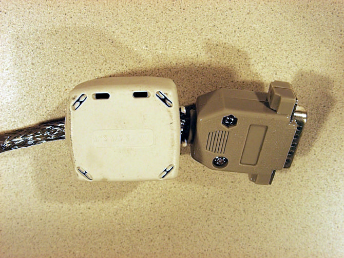
Appendix 2 Photodocumentation Description: PCI-Card installed into PC Medizintechnik/Nach- richtentechnik/EMV Department: EMC Test report reference: M/EMV-02/136 Page: 13 of 27 Date: 22.05.2002 checked by: _______ Appendix 2 Photodocumentation Description: Connector and LEDs Medizintechnik/Nach- richtentechnik/EMV Department: EMC Test report reference: M/EMV-02/136 Page: 14 of 27 Date: 22.05.2002 checked by: _______ Appendix 2 Photodocumentation Description: Cable connected Medizintechnik/Nach- richtentechnik/EMV Department: EMC Test report reference: M/EMV-02/136 Page: 15 of 27 Date: 22.05.2002 checked by: _______ Appendix 2 Photodocumentation Description: Original cable Medizintechnik/Nach- richtentechnik/EMV Department: EMC Test report reference: M/EMV-02/136 Page: 16 of 27 Date: 22.05.2002 checked by: _______ Appendix 2 Photodocumentation Description: Detail view of PC connector Medizintechnik/Nach- richtentechnik/EMV Department: EMC Test report reference: M/EMV-02/136 Page: 17 of 27 Date: 22.05.2002 checked by: _______ Appendix 2 Photodocumentation Description: Powerline connector view #1 Medizintechnik/Nach- richtentechnik/EMV Department: EMC Test report reference: M/EMV-02/136 Page: 18 of 27 Date: 22.05.2002 checked by: _______ Appendix 2 Photodocumentation Description: Powerline connector view #2 Medizintechnik/Nach- richtentechnik/EMV Department: EMC Test report reference: M/EMV-02/136 Page: 19 of 27 Date: 22.05.2002 checked by: _______

Internal Photos

Appendix 2 Photodocumentation Description: PCI-Card view #1 Medizintechnik/Nach- richtentechnik/EMV Department: EMC Test report reference: M/EMV-02/136 Page: 1 of 27 Date: 22.05.2002 checked by: _______ Appendix 2 Photodocumentation Description: Detail view #1 Medizintechnik/Nach- richtentechnik/EMV Department: EMC Test report reference: M/EMV-02/136 Page: 2 of 27 Date: 22.05.2002 checked by: _______ Appendix 2 Photodocumentation Description: Detail view #2 Medizintechnik/Nach- richtentechnik/EMV Department: EMC Test report reference: M/EMV-02/136 Page: 3 of 27 Date: 22.05.2002 checked by: _______ Appendix 2 Photodocumentation Description: Screening of connector Medizintechnik/Nach- richtentechnik/EMV Department: EMC Test report reference: M/EMV-02/136 Page: 4 of 27 Date: 22.05.2002 checked by: _______ Appendix 2 Photodocumentation Description: 100 MHz crystal view #1 Medizintechnik/Nach- richtentechnik/EMV Department: EMC Test report reference: M/EMV-02/136 Page: 5 of 27 Date: 22.05.2002 checked by: _______ Appendix 2 Photodocumentation Description: 100 MHz crystal view #2 Medizintechnik/Nach- richtentechnik/EMV Department: EMC Test report reference: M/EMV-02/136 Page: 6 of 27 Date: 22.05.2002 checked by: _______ Appendix 2 Photodocumentation Description: 25 MHz crystal Medizintechnik/Nach- richtentechnik/EMV Department: EMC Test report reference: M/EMV-02/136 Page: 7 of 27 Date: 22.05.2002 checked by: _______ Appendix 2 Photodocumentation Description: Detail view #3 Medizintechnik/Nach- richtentechnik/EMV Department: EMC Test report reference: M/EMV-02/136 Page: 8 of 27 Date: 22.05.2002 checked by: _______ Appendix 2 Photodocumentation Description: Detail view #4 Medizintechnik/Nach- richtentechnik/EMV Department: EMC Test report reference: M/EMV-02/136 Page: 9 of 27 Date: 22.05.2002 checked by: _______ Appendix 2 Photodocumentation Description: PCI-Card view #2 Medizintechnik/Nach- richtentechnik/EMV Department: EMC Test report reference: M/EMV-02/136 Page: 10 of 27 Date: 22.05.2002 checked by: _______ Appendix 2 Photodocumentation Description: Detail view #5 Medizintechnik/Nach- richtentechnik/EMV Department: EMC Test report reference: M/EMV-02/136 Page: 11 of 27 Date: 22.05.2002 checked by: _______ Appendix 2 Photodocumentation Description: Detail view #6 Medizintechnik/Nach- richtentechnik/EMV Department: EMC Test report reference: M/EMV-02/136 Page: 12 of 27 Date: 22.05.2002 checked by: _______ Appendix 2 Photodocumentation Description: PC connector opened Medizintechnik/Nach- richtentechnik/EMV Department: EMC Test report reference: M/EMV-02/136 Page: 20 of 27 Date: 22.05.2002 checked by: _______ Appendix 2 Photodocumentation Description: Powerline connector opened view #1 Medizintechnik/Nach- richtentechnik/EMV Department: EMC Test report reference: M/EMV-02/136 Page: 21 of 27 Date: 22.05.2002 checked by: _______ Appendix 2 Photodocumentation Description: Powerline connector opened view #2 Medizintechnik/Nach- richtentechnik/EMV Department: EMC Test report reference: M/EMV-02/136 Page: 22 of 27 Date: 22.05.2002 checked by: _______ Appendix 2 Photodocumentation Description: Powerline connector opened view #3 Medizintechnik/Nach- richtentechnik/EMV Department: EMC Test report reference: M/EMV-02/136 Page: 23 of 27 Date: 22.05.2002 checked by: _______

Operational Description

OPERATIONAL DESCRIPTION Corinex PowerNet PCI card includes: - PCI card - PCI outlet PCI card: 1) MAC controller RTL8130 with MII interface. -Into the controller from PCI BUS is entering 33MHz PCI clock. - To the controller is connected external crystal 25MHz. - From RTL8130 is going Tx clock and Rx clock with frequency 25 MHz into the circuit of the physical interface INT 5130 2) Circuit of the physical interfaces INT5130. - To the circuit is connected external crystal 100MHz (20MHz – 5-th harmonic frequency). - In INT5130 is open also clock signal DAC CLK 50MHz for DAC/ADC converter of the INT 1000. 3) AD/DA converter INT 1000 - From converter DAC ADC INT 1000 is going through the 10 bit bus digital signal into INT 5130 - Analog signal in the range 4-21 MHz is outgoing to the analogue part 4) Analogue part (OUT) - Frequency from DAC INT 1000 is going through band pass 4-21 MHz, amplifier with amplify An=1, suppressor diodes, band pass 4-21 MHz once again and connector J2 (7W2) 5) Analogue part (IN) - Aquired signal from PCI outlet is going from connector J2 (7W2) through the suppressor diodes to the circuit AGC on entry ADC INT 1000. To the connector J2 (7W2) there connected signals: - RXIN w hic h is goi ng to the PC I o utlet - TXOUT going to the PCI outlet - Power supply of the PCI outlet +12VDC through the fuse 630mA - TXEN w hich is connected blocking capacitor to the Ground PCI outlet: Consists from connector, which should be inserted into the PCI card, and 1.5m of shielded cable with additional shielded copper folium Signals TXOUT and TXIN are carried on independently shielded wires, signals TXEN and +12VDC are carried through the wires with common shielding. 1. Analogue part (OUT): Signal from PCI card is going through the cable suppressor diodes, amplifier with amplify AN=2. ) through switch T/R SWITCH and through suppressor diodes on winding separating transformer. 2,Analogue part (IN): Signal from separating transformer going through suppressor diodes, band pass 4 – 21 MHz, suppressor diodes, amplifier, suppressor diodes and through cables to PCI card. 3,POWER part: Separating transformer is winding on toroid core. Signal from secondary winding going through parallel coupling capacitor 10nF/400V a resistor 100kohm/500Vef. Parallel coupling varistor Uv=240 and fuse 630mA. Transient voltage suppressors SAC 5,0. Peak pulse power dissipation with a 10/1000us minimum 500W. Peak pulse power surge current with a 10/1000us minimum 44A.

Schematics

ScaleSheet SizeFCSM No.DWG No.Rev 1 of 1 Cv1.02 Corinex Global a.s. Ruzova Dolina 19 82108 Bratislava Slovakia CX POWERNET OUTLET C29 10NF/250V R28 100K(1/4W) MOV2 ERZ-V07D241 AC LINE D8 SAC5_0 D9 SAC5_0 LINE NEUTRAL LINE COUPLING C28 100N -IN 2 +IN 3 OUT 1 +Vs 8 -Vs 4 U2A AD8017AR -IN 6 +IN 5 OUT 7 U2B AD8017AR C30 100N R29 47 +12A R30 330 R31 150 +12A L12 1_5UH(5%) C41 330PFC L11 1_5UH(5%) C38 180PFC L10 560N C35 120PFC C37 330PFC C36 270PFC L9 680N L8 470N INPUT BPF (4.3 to 20.9 Mhz) C24 100N C34 100N R32 1K R33 1K +12A C33 2N2 R34 47 C17 100N +12A +12A C15 100N C25 100N R14 1K R19 1K +12A R13 120 R10 120 C16 2N2 R24 6R8 C26 220N T/R SWITCH R20 680 R23 1K5 R25 47 R26 10K R27 56 C27 100N +12A C32 100N C31 100N L7 10UH-NLC + C44 100UF-16V +12A +12A TXOUT +12A RXIN TXEN K3 LINE K4 NEUTRAL TXOUT TXOUT TXEN TXEN +12 +12 RXIN RXIN Q3 BC817-16 2 3 1 D6 BAV99 2 3 1 D10 BAV99 2 3 1 D7 BAV99 T2 Q4 BC807-16 C42 560P C39 560P C40 56P C43 56P 1 2 3 J1 CON7_TX 1 2 3 J3 CON7_RX 1 2 J2 CON7_EN F1 630MA C1 10N R1 120 +12A 123456789 D C B A VDD_C 1 VDD_C 2 VDD_IO 3 MII_TX3 4 VSS_C 5 MII_TX2 6 VDD_C 7 MII_TX1 8 VSS_IO 9 VSS_C 10 MII_TX0_GPSI_TXD 11 MII_TXEN_GPSI_TXEN 12 VDD_C 13 MII_TXCLK_GPSI_TXCLK 14 VDD_Q 15 MII_TX_ER 16 VDD_C 17 MII_RX_ER_GPSI_RXD 18 VSS_C 19 VSS_C 20 VSS_Q 21 MII_RXCLK_GPSI_RXCLK 22 VDD_C 23 VDD_C 24 MII_RXDV_GPSI_TXBSY 25 VSS_C 26 MII_RX3 27 VDD_C 28 MII_RX2 29 VSS_C 30 MII_RX1 31 VDD_C 32 MII_RX0 33 VSS_C 34 VSS_IO 35 VSS_C 36 VDD_C 37 VDD_C 38 VDD_IO 39 MII_COL_GPSI_COL 40 VSS_C 41 MII_CRS_GPSI_RXEN 42 VDD_C 43 RESET_N 44 VSS_IO 45 VSS_C 46 VSS_C 47 CLKOUT 48 CLKIN 49 VDD_C 50 VDD_Q 51 SPI_CS 52 VDD_C 53 SPI_SCLK 54 VSS_C 55 VSS_C 56 SPI_DI 57 VSS_C 58 SPI_DO 59 VDD_C 60 LED0_N 61 VSS_C 62 LED1_N 63 VDD_IO 64 LED2_N 65 VSS_C 66 ADC_CAL 67 VDD_C 68 AGCENC_N 69 VSS_IO 70 ADC_CLK 71 VSS_C 72 VDD_C 73 DAC_CLK 74 VSS_C 75 TX_EN 76 RX_EN 77 VDD_C 78 VDD_IO 79 ADIO0 80 ADIO1 81 ADIO2 82 VSS_IO 83 ADIO3 84 VSS_C 85 ADIO4 86 ADIO5 87 VSS_C 88 VSS_Q 89 ADIO6 90 VDD_Q 91 ADIO7 92 ADIO8 93 ADIO9 94 VDD_IO 95 AGC0 96 AGC1 97 AGC2 98 VDD_C 99 AGC3 100 VSS_C 101 AGC4 102 AGC5 103 VDD_C 104 AGC6 105 AGC7 106 VSS_IO 107 VSS_C 108 VDD_C 109 VDD_IO 110 TEST1 111 TEST2 112 VSS_C 113 TCK 114 VDD_C 115 TDO 116 VSS_C 117 VSS_C 118 VSS_C 119 TDI 120 VDD_C 121 VDD_C 122 VDD_C 123 TMS 124 VDD_C 125 MDI_SPIS_N 126 VSS_C 127 VSS_C 128 TRST_N 129 VSS_Q 130 NC 131 VDD_C 132 MII_MDCLK_SPIS_SCLK 133 VSS_C 134 MII_MDIO_SPIS_SDO 135 VDD_IO 136 MDI_ADRSEL[1]_SPIS_SDI 137 VSS_C 138 MDI_ADRSEL[0]_SPIS_CS_N 139 VDD_C 140 MII_GPSI_N 141 VSS_IO 142 VSS_C 143 VSS_C 144 U5 INT5130-LQFP144 C26 15P C25 15P L1 0_22UH R10 22 R9 100K C27 10N 5130_CLKOUT 5130_CLKIN +3_3D +2_5D R11 10K +3_3D R13 10K +3_3D R12 10K +3_3D+2_5D +3_3D +2_5D +3_3D+2_5D +3_3D +2_5D MII_TXD0_GPSI_TXD MII_TXD1 MII_TXD2 MII_TXD3 MII_TXEN_GPSI_TXEN MII_TXCLK_GPSI_TXCLK MII_TX_ER MII_RX_ER_GPSI_RXD MII_RXCLK_GPSI_RXCLK MII_RXDV_GPSI_TXBSY MII_RXD0 MII_RXD1 MII_RXD2 MII_RXD3 MII_COL_GPSI_COLMII_CRS_GPSI_RXENRESET_N5130_CLKOUT5130_CLKINSPI_CSSPI_SCLKSPI_DISPI_DOCOLLISION_LED_NACTIVITY_LED_NLINK_LED_NADC_CALADC_CLK AGC0 AGC1 AGC2 AGC3 AGC4 AGC5 AGC6 AGC7 ADIO0 ADIO1 ADIO2 ADIO3 ADIO4 ADIO5 ADIO6 ADIO7 ADIO8 ADIO9 RX_EN TX_EN DAC_CLK C78 15U/6.3V C80 15U/6.3V C79 15U/6.3V C81 15U/6.3V MDI_SPIS_NMII_MDCLK_SPIS_SCLKMII_MDIO_SPIS_SDOMII_GPSI_N 1TP1 +3_3D 1TP2 +3_3DM 1TP3 +2_5D 1TP4 +2_5DM C28 100N 1K C29 100P +3_3D R66 270 COLLISION_LED_N R65 270 ACTIVITY_LED_N R67 270 LINK_LED_N REAR PANEL COLLISION ACTIVITY LINK STATUS DS2 LED-RED DS1 LED-GREEN DS3 LED-YELLOW +3_3D+3_3D GND 1 RST 2 VCC 3 GND 4 U2 DS1233A C70 15U/6.3V C77 15U/6.3VR49 10K +3A C72 100N C75 100N +5A L9 22U C153 100N C154 100N C155 15U/6.3V C152 15U/6.3V P5VA Vout 1 GND 2 GND 3 NC 4 INH 5 GND 6 GND 7 Vin 8 U9 LE33CD Y1 100M 2 3 1 D4 BAV99 R15 47 +3_3D C31 100N TX_EN TXEN A3 9 A4 12 B2 5 B3 10 B4 13 Y3 8 Y4 11 GND 7 74HCT08 R26 4K7 GND PCI_RST_N PCI_GNT_N PCI_PME_N PCI_AD_30 PCI_AD_28 PCI_AD_26 PCI_AD_24 PCI_IDSEL PCI_AD_22 PCI_AD_20 PCI_AD_18 PCI_AD_16 PCI_FRAME_N PCI_TRDY_N PCI_STOP_N PCI_PAR PCI_AD_15 PCI_AD_13 PCI_AD_11 PCI_AD_09 PCI_CBE0_N PCI_AD_06 PCI_AD_04 PCI_AD_02 PCI_AD_00 PCI_TCK TEST LOOP PCI_CLK PCI_REQ_N PCI_AD_31 PCI_AD_29 PCI_AD_27 PCI_AD_25 PCI_CBE3_N PCI_AD_23 PCI_AD_21 PCI_AD_19 PCI_AD_17 PCI_CBE2_N PCI_IRDY_N PCI_DEVSEL_N PCI_PERR_N PCI_SERR_N PCI_CBE1_N PCI_AD_14 PCI_AD_12 PCI_AD_10 PCI_AD_08 PCI_AD_07 PCI_AD_05 PCI_AD_03 PCI_AD_01 P5VA RESERVED A9 +V-IO A10 RESERVED A11 3.3VAUX A14 RST# A15 +V-IO A16 GNT# A17 GND A18 PME# A19 AD[30] A20 +3.3V A21 AD[28] A22 AD[26] A23 GND A24 AD[24] A25 IDSEL A26 +3.3V A27 AD[22] A28 AD[20] A29 GND A30 AD[18] A31 AD[16] A32 +3.3V A33 FRAME# A34 GND A35 TRDY# A36 GND A37 STOP# A38 +3.3V A39 RESERVED A40 RESERVED A41 GND A42 PAR A43 AD[15] A44 +3.3V A45 AD[13] A46 AD[11] A47 GND A48 AD[9] A49 C/BE[0]# A52 +3.3V A53 AD[06] A54 AD[04] A55 GND A56 AD[02] A57 AD[00] A58 +V-IO A59 REQ64# A60 +5V A61 +5V A62 KEYWAY KEYWAY KEYWAY KEYWAY PCI-UNI-EDGE-32BIT -12V B1 TCK B2 GND B3 TDO B4 +5V B5 +5V B6 INTB# B7 INTD# B8 PRSNT1# B9 RESERVED B10 PRSNT2# B11 RESERVED B14 GND B15 CLK B16 GND B17 REQ# B18 +V-IO B19 AD[31] B20 AD[29] B21 GND B22 AD[27] B23 AD[25] B24 +3.3V B25 C/BE[3]# B26 AD[23] B27 GND B28 AD[21] B29 AD[19] B30 +3.3V B31 AD[17] B32 C/BE[2]# B33 GND B34 IRDY# B35 +3.3V B36 DEVSEL# B37 GND B38 LOCK# B39 PERR# B40 +3.3V B41 SERR# B42 +3.3V B43 C/BE[1]# B44 AD[14] B45 GND B46 AD[12] B47 AD[10] B48 M66EN B49 AD[08] B52 AD[07] B53 +3.3V B54 AD[05] B55 AD[03] B56 GND B57 AD[01] B58 +V-IO B59 ACK64# B60 +5V B61 +5V B62 KEYWAY KEYWAY KEYWAY KEYWAY P1B PCI-UNI-EDGE-32BIT AD31 108 AD30 109 AD29 110 AD28 111 AD27 113 AD26 114 AD25 115 AD24 116 AD23 120 AD22 121 AD21 123 AD20 124 AD19 125 AD18 126 AD17 127 AD16 129 AD15 142 AD14 143 AD13 144 AD12 145 AD11 147 AD10 148 AD9 149 AD8 150 AD7 153 AD6 154 AD5 155 AD4 157 AD3 158 AD2 159 AD1 160 AD0 1 C/BE3 118 C/BE2 130 C/BE1 140 C/BE0 152 CLK 104 DEVSELB 135 FRAMEB 131 IRDYB 132 TRDYB 133 STOPB 136 PERRB 137 SER…

Text truncated - open the document above for the full version.

Test Report

File: 02-136.docPage 1 of 2622.05.2002 TEST REPORT of the accredited test laboratory TÜV Nr.:M/EMV-02/136 about the following EMC - test/- research Applicant: Corinex Global a.s. Klukatá 6 82108 Bratislava, Slovakia Product: Corinex Powernet PCI Serial Number: --- Standard: EN 55022:1998; EN 55024:1998; EN 61000-3-2/A14:2001; EN 61000-3-3:1995; CISPR 22:1997 TÜV Österreich Test laboratory for EMC Deputy Supervisor of EMC- laboratory Ing. Wilhelm Seier Official seal 22.05.2002 Checked by Ing. Klaus Rötsch Copy Nbr.:______ A publication of this test report is only permitted literally. Copying or reproduction of partial sections needs a written permission of TÜV Österreich. The results of this test report only refer to the provided equipment. Division Medical Technology/ Communication Technology/ EMC Testing Body for Communication Technology/ EMC Prüfzentrum Wien A-1230 Wien Deutschstraße 10 Tel.: +43 1 / 610 91 Fax: Ext. 6505 Mail: [email protected] Accredited Testing Laboratory, Inspection Body, Certification Body, Calibration Body Notified Body 0408 DVR 0047 333 UID ATU 37086005 Test report number: M/EMV-02/136 Date: 22.05.2002 File: 02-136.docPage 2 of 26checked by: ________ Contents Designationpage 1.Applicant3 2.Description of EUT4 3.Standards / Final result5 4.Test results6-26 AppendixDesignationpages 1Test equipment used3 2Photodocumentation27 3Measurement diagrams3 Test report number: M/EMV-02/136 Date: 22.05.2002 File: 02-136.docPage 3 of 26checked by: ________ 1.Applicant CompanyCorinex Global a.s. Department Address82108 Bratislava, Slovakia; Klukatá 6 Contact personMr. Hradilek EUT received onMay 16th 2002 Tests were performed onMay 16th till 21st 2002 Test report number: M/EMV-02/136 Date: 22.05.2002 File: 02-136.docPage 4 of 26checked by: ________ 2.Description of EUT EUTCorinex Powernet PCI Serial Number--- ManufacturerCorinex Global a.s. 82108 Bratislava, Slovakia; Klukatá 6 DescriptionCorinex Global a.s. provided the following configuration for the measurements: PCI-Powernetadapter installed in a PC PC: “forte” CE marked (not for US market) Noname-Keypad made in Thailand with FCC statements Microsoft-mouse FCC-ID: C3KSS1 Operating modeThe measurements were carried out at the following running states: transmit/receive data Test report number: M/EMV-02/136 Date: 22.05.2002 File: 02-136.docPage 5 of 26checked by: ________ 3.Standards / Final result NameTitleDeviationResult EN 55022:1998Limits and methods of measurement of radio disturbance characteristics of information technology equipment nonePASS EN 55024:1998Information technology equipment - Immunity characteristics - Limits and methods of measurement nonePASS EN 61000-3-2/A14:2001 Electromagnetic compatibility (EMC) Part 3: Limits Section 2:Limits for harmonic current emissions (equipment input current up to and including 16A per phase) nonePASS EN 61000-3-3:1995Electromagnetic compatibility (EMC) Part 3: Limits Section 2:Limitation of voltage fluctuations and flicker in low-voltage supply systems for equipment with rated current up to and including 16A nonePASS CISPR 22:1997Limits and methods of measurement of radio disturbance characteristics of information technology equipment nonePASS PASSEUT passed FAILEUT failed Test report number: M/EMV-02/136 Date: 22.05.2002 File: 02-136.docPage 6 of 26checked by: ________ 4.Test results 4. 1.Conducted emission Limits Frequeny rangeLimit DetectorQuasi PeakAverage 0,150 - 0,5 MHz66 - 56 dBμV decreasing with the logarithm of frequency 56 - 46 dBμV decreasing with the logarithm of frequency 0,5 - 5 MHz56 dBμV46 dBμV 5 - 30 MHz60 dBμV50 dBμV Remark: Quasi Peak and Average limits must be both met Measuring apparatus parameters: ParameterPreview measurement Final measurement ParameterPreview measurement Final measurement Start frequency150 kHz150 kHzDetectorMP/AVQP/AV Stop frequency30 MHz30 MHzMeasuring time10 ms1 s Stepsize5 kHz5 kHzRF-attenuation0dB0dB IF- Bandwidth9 kHz9 kHzPreamplifier0 dB0 dB Operating modeMeasuring result transmit/receive dataMeasurement diagram 1 Test report number: M/EMV-02/136 Date: 22.05.2002 File: 02-136.docPage 7 of 26checked by: ________ Test result: 4. 1.1.) Measurement with QP-Detector FrequencyLevelLimitMarginExceed-PhasePE MHzdBμVdBμVdBMark 0,29058,860,61,8NGND 0,37051,658,56,9NGND 4,69049,656,06,4L1GND 4,88550,256,05,8L1GND 16,19549,760,010,3L1GND 19,93051,060,09,0L1GND Test report number: M/EMV-02/136 Date: 22.05.2002 File: 02-136.docPage 8 of 26checked by: ________ 4. 1.2.) Measurement with AV-Detector FrequencyLevelLimitMarginExceed-PhasePE MHzdBμVdBμVdBMark 4,48539,446,06,6L1GND 4,69540,346,05,7L1GND 4,88541,346,04,7L1GND 19,72041,550,08,5L1GND 19,92040,250,09,8L1GND 20,50043,550,06,5NGND Test report number: M/EMV-02/136 Date: 22.05.2002 File: 02-136.docPage 9 of 26checked by: ________ 4. 2.Radiated emission Limits : Frequency rangeLimit (quasi peak) 30 - 230 MHz39,6 dBμV/m 230 - 1000 MHz46,6 dBμV/m Measuring apparatus parameters: ParameterPreview measurement Final measurement ParameterPreview measurement Final measurement Start frequency30 MHz30 MHzDetectorMax PeakQuasi Peak Stop frequency1000 MHz1000 MHzMeasuring time10 ms1 s Stepsize50 kHz50 kHzRF-attenuation0dB0dB IF- Bandwidth120 kHz120 kHzPreamplifier20 dB20 dB Operating modeMeasuring result transmit/receive dataMeasurement diagram 2, 3 Test report number: M/EMV-02/136 Date: 22.05.2002 File: 02-136.docPage 10 of 26checked by: ________ Test result: 4. 2.1.) Measurement with QP-Detector (30 MHz - 200 MHz) FrequencyLevelLimitMarginExceed-HeightAzimuthPolarization MHzdBμV/mdBμV/mdBMarkcmdeg 32,7530,339,69,3100160Vertical 143,0529,939,69,7200250Horizontal 144,7532,239,67,4217239Horizontal 146,5027,539,612,1223226Horizontal 149,9527,039,612,6227264Horizontal Test report number: M/EMV-02/136 Date: 22.05.2002 File: 02-136.docPage 11 of 26checked by: ________ 4. 2.2.) Measurement with QP-Detector (200 MHz - 1000 MHz) FrequencyLevelLimitMarginExceed-HeightAzimuthPolarization MHzdBμV/mdBμV/mdBMarkcmd…

Text truncated - open the document above for the full version.

Test Setup Photos

Appendix 2 Photodocumentation Description: Test setup radiated emission, view #1 Medizintechnik/Nach- richtentechnik/EMV Department: EMC Test report reference: M/EMV-02/136 Page: 24 of 27 Date: 22.05.2002 checked by: _______ Appendix 2 Photodocumentation Description: Test setup radiated emission, view #2 Medizintechnik/Nach- richtentechnik/EMV Department: EMC Test report reference: M/EMV-02/136 Page: 25 of 27 Date: 22.05.2002 checked by: _______ Appendix 2 Photodocumentation Description: Test setup conducted emission, view #1 Medizintechnik/Nach- richtentechnik/EMV Department: EMC Test report reference: M/EMV-02/136 Page: 26 of 27 Date: 22.05.2002 checked by: _______ Appendix 2 Photodocumentation Description: Test setup conducted emission, view #2 Medizintechnik/Nach- richtentechnik/EMV Department: EMC Test report reference: M/EMV-02/136 Page: 27 of 27 Date: 22.05.2002 checked by: _______

Contact Information

Applicant

Gabriel Hradilek(COO)
[email protected]00421-2-5021 4811Fax: 00421-2-5556 7309

Technical Contact

Corinex Global, a.s.Gabriel Hradilek
[email protected]00421-2-5021 4811

Klukata 6, · Bratislava · Slovak Republic

Non-Technical Contact

Corinex Global, a.s.Gabriel Hradilek
[email protected]00421-2-5021 4811

Test Firm

TUV AustriaIng Wilhelm Seier
[email protected]43-1-610-91-6530Fax: +43 1 610 91 6505

Technical Specifications

#Rule PartsFrequency RangePower Output
115B--

Other Applications from Corinex Global, a.s.

QD9POWERNET-USB

Powerline Telecommunication Modem for USB bus

Jul 18, 2002

Equipment Class

JBP - Part 15 Class B Computing Device Peripheral