QDAAEM3000DCUAVL and Data Logging System
Minorplanet Systems PLC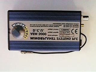
Click to zoom
Application Details
- Equipment Class
- DXX - Part 15 Low Power Communication Device Transmitter
- Date of Grant
- Jul 18, 2002
- Application Purpose
- Original Equipment
- Date of Application
- May 12, 2002
- Equipment Note
- AVL and Data Logging System
- Frequency Range
- 902.60000000 - 902.60000000
- Company
- Minorplanet Systems PLC
- Country
- United Kingdom
Documents & Files
Document Text
Text extracted from the exhibit documents filed with the FCC. Open a document above to read the original.
Users Manual
MINORPLANET AEM3000 DCU AVL & Data Logging System System overview & Installation Guide AEM3000 DCU WM1002 B Issue 1 page 1 of 13 MINORPLANET Contents Page 1. Operation System Configuration .......................................................................3 System Overview ..............................................................................3 System Operation .............................................................................4 Component Layout ........................................................................... 4 2. Safety Precautions General Safety ..................................................................................5 Electrical Safety ................................................................................ 5 Safety Standards ............................................................................... 5 3. General Installation Mechanical Assembly ....................................................................... 6 DCU Installation ................................................................................ 7 Electrical Wiring ................................................................................ 8 GPS Antenna Fitting ......................................................................... 9 GSM Antenna Fitting ........................................................................ 10 4. Commissioning Test Procedures ............................................................................... 10 Trouble Shooting ...............................................................................11 5. Technical Specifications Mechanical Specification ...................................................................12 Electrical Specification .......................................................................12 GPS Antenna Specification ................................................................12 GSM Antenna Specification ................................................................12 AEM3000 DCU WM1002 B Issue 1 page 2 of 13 MINORPLANET 1. OPERATION 1.1 Maptrack System Overview The Maptrack system brings together satellite based global positioning technology, microprocessor control, low power radio and international GSM communication infrastructure to achieve wide area communication, vehicle location, telematics and communication services. 1.1.1 OPERATION OVERVIEW 1.2 System Overview The AEM3000 is an electronic data collection and transmission device, incorporating GPS tracking and GSM communication technologies. Whilst the vehicle is in use, geographical and operational data is continually monitored and recorded within the DCU (data collection unit) memory. Up to 8 weeks of operational data can be held within the DCU. If the memory capacity is reached before the data is downloaded, the oldest records will be lost as new records are recorded. Recorded data may be downloaded for processing by the base computer in the following ways; a) bulk download of all held data via the GSM data channel b) snap shot of current ‘live’ data via the GSM SMS network. c) bulk download of held data via the low power radio interface upon return to base. Interrogation of the DCU is possible anywhere that benefits from GSM network coverage (subject to roaming agreements with GSM networks). AEM3000 DCU WM1002 B Issue 1 page 3 of 13 MINORPLANET 1.3 System Operation The Maptrack in-vehicle system consists of the DCU (data collection unit), GPS and GSM antennae. Only power and ignition connections are made to the vehicle electrical system. When an ignition signal is present at the DCU the system records a start event and activates the GPS receiver, the vehicles geographical position, velocity and distance travelled are then continually recorded within the DCU until the ignition signal is removed, at which time a stop event is recorded, the DCU then performs any outstanding tasks before powering down the GPS receiver and GSM transceiver. The DCU will stay in this power save mode until either the ignition is turned on or a command is received form the monitoring bureau to reactivate. 1.4 Component Layout The following equipment positioning guides are for reference only and are not intended to be exhaustive. Actual optimum positions will change depending upon type of vehicle being fitted. 1.4.1 DCU POSITION GUIDE (within vehicle) 1.4.2 TRI-BAND AERIAL POSITION GUIDE (roof of vehicle) AEM3000 DCU WM1002 B Issue 1 page 4 of 13 MINORPLANET SAFETY PRECAUTIONS 2.1 General Safety It is the installation engineers’ responsibility to asses all potential risks before commencing work on the host vehicle and be fully conversant with all vehicle operating procedures and workshop practices. The following points are for guidance only and are not intended to be exhaustive: 2.1.1 never work under a vehicle, which is supported solely by jacks. 2.1.2 the vehicle should always be left out of gear. 2.1.3 never perform any tasks, which would jeopardise your own or the operational safety of the vehicle. 2.1.4 always remove and replace vehicle trim with correct tools and in line with manufacturers instructions. 2.1.5 take extreme caution not to damage or disrupt air bag or supplementary restraint systems (SRS). 2.1.6 if additional mountings are required, these should be drilled within the vehicle manufacturers guidelines. 2.1.7 never operate the system with damaged unapproved parts. 2.2 Electrical Safety It is the installation engineer’s responsibility to asses all potential risks before commencing work on the host vehicle and be fully conversant with all auto electrical procedures and workshop practices. The following points are for guidance only and are not intended to be all-inclusive: 2.2.1 it is advisable to disconnect the vehicle battery prior to making any electrical connections. 2.2.2 never attempt to test any electrical circuits using a test lamp. 2.2.3 remove or cover any jewellery if it is necessary to work on live electrical systems. 2.2.4 ne…
Text truncated - open the document above for the full version.
Block Diagram
AEM3000 Block Diagram INFO.DOCU.0009 MINORPLANET SYSTEMS PLC AEM3000 Block Diagram Revision History Issue Date Engineer Checked Notes 1 8 th April 2002 M. GjessingJ. Macey First issue. Input power from vehicle 8-31V D.C. 902.75MHz local download antenna. 902.75MHz local download Transceiver. Main internal power supply +5V D.C. Microprocessor. GPS assembly. Motorola D15 power supply +5V D.C. Motorola D15 GSM Modem. GPS antenna. GSM antenna. Copyright Minorplanet Systems plc. Unaurthorized re production and distribution is prohibited Page 1 of 1
ID Label/Location Info
AEM3000 Label INFO.DOCU.0010 MINORPLANET SYSTEMS PLC AEM3000 Label Revision History Issue Date Engineer Checked Notes 1 15 th April 2002 M. GjessingJ. Macey First issue. 2 13 th May 2002 M. GjessingJ. Macey FCC ID added. Please take note: the label diagram shown below is not drawn to size. Actual size of label is 135mm X 40mm. 13 th May 2002 Copyright Minorplanet Systems plc. Unauthorized re production and distribution is prohibited Page 1 of 1
ID Label/Location Info
AEM3000 Label INFO.DOCU.0010 17 th May 2002 MINORPLANET SYSTEMS PLC Copyright Minorplanet Systems plc. Unauthorized reproduction and distribution is prohibited Page 1 of 1 AEM3000 Label Revision History IssueDateEngineerCheckedNotes 115 th April 2002M. GjessingJ. MaceyFirst issue. 213 th May 2002M. GjessingJ. MaceyFCC ID added. 317 th May 2002M. GjessingJ. MaceyThe word “Number” removed from the FCC ID. Please take note: the label diagram shown below is not drawn to size. Actual size of label is 135mm X 40mm.
Internal Photos
Christian Pickard Direct line +44 (0) 113 3847145 Mobile +44 (0) 7831 362206 e-mail [email protected] Christian Pickard Direct line +44 (0) 113 3847145 Mobile +44 (0) 7831 362206 e-mail [email protected]
Operational Description
MINORPLANET 1. OPERATION 1.1 Maptrack System Overview The Maptrack system brings together satellite based global positioning technology, microprocessor control, low power radio and international GSM communication infrastructure to achieve wide area communication, vehicle location, telematics and communication services. 1.1.1 OPERATION OVERVIEW 1.2 System Overview The AEM3000 is an electronic data collection and transmission device, incorporating GPS tracking and GSM communication technologies. Whilst the vehicle is in use, geographical and operational data is continually monitored and recorded within the DCU (data collection unit) memory. Up to 8 weeks of operational data can be held within the DCU. If the memory capacity is reached before the data is downloaded, the oldest records will be lost as new records are recorded. Recorded data may be downloaded for processing by the base computer in the following ways; a) bulk download of all held data via the GSM data channel b) snap shot of current ‘live’ data via the GSM SMS network. c) bulk download of held data via the low power radio interface upon return to base. Interrogation of the DCU is possible anywhere that benefits from GSM network coverage (subject to roaming agreements with GSM networks). AEM3000 DCU WM1002 B Issue 1 page 3 of 13 MINORPLANET 1.3 System Operation The Maptrack in-vehicle system consists of the DCU (data collection unit), GPS and GSM antennae. Only power and ignition connections are made to the vehicle electrical system. When an ignition signal is present at the DCU the system records a start event and activates the GPS receiver, the vehicles geographical position, velocity and distance travelled are then continually recorded within the DCU until the ignition signal is removed, at which time a stop event is recorded, the DCU then performs any outstanding tasks before powering down the GPS receiver and GSM transceiver. The DCU will stay in this power save mode until either the ignition is turned on or a command is received form the monitoring bureau to reactivate. 1.4 Component Layout The following equipment positioning guides are for reference only and are not intended to be exhaustive. Actual optimum positions will change depending upon type of vehicle being fitted. 1.4.1 DCU POSITION GUIDE (within vehicle) 1.4.2 TRI-BAND AERIAL POSITION GUIDE (roof of vehicle) AEM3000 DCU WM1002 B Issue 1 page 4 of 13
Parts List/Tune Up Info
Bill of Materials ELEC.UNIT.0001.0003 UNIT.EBOM.0001.0003 MINORPLANET SYSTEMS PLC Copyright Minorplanet Systems plc. Unauthorized reproduction and distribution is prohibited 01/03/2002 UNIT.EBOM.0001.0003 Issue 3 Page 1 Bill of Materials for ELEC.UNIT.0001.0003 Revision History Issue Date Engineer Checked Change NoteNotes 1 23/11/00 S. M. Dilkes M. Gjessing N/A First Issue 2 29/01/01 S. M. Dilkes J. S. Shaw 01/01 Capacitor C1E Removed 3 01/03/02 K Singh S. M. Dilkes 09/02 Inductor Part Field 1 updated Part Type Designator Part Field 1 Part Field 2 Part Field 3 CAPACITOR C1A COMP.ALEC.S001.0002 CAPACITOR C1B COMP.ALEC.S001.0001 COMP.ALEC.S001.0002 CAPACITOR C1C COMP.ALEC.S001.0001 COMP.ALEC.S001.0002 CAPACITOR C1D COMP.ALEC.S001.0001 COMP.ALEC.S001.0002 CAPACITOR C2A COMP.ALEC.S002.0001 COMP.ALEC.S002.0002 COMP.ALEC.S002.0003 CAPACITOR C2B COMP.ALEC.S002.0002 COMP.ALEC.S002.0003 CAPACITOR C2C COMP.ALEC.S002.0003 CAPACITOR C3 COMP.MLCC.S009.0104 CAPACITOR C4 COMP.MLCC.S007.0103 CAPACITOR C5 COMP.MLCC.S009.0104 CAPACITOR C6 COMP.MLCC.S009.0104 CAPACITOR C7 COMP.MLCC.S009.0104 CAPACITOR C8 COMP.MLCC.S009.0104 CAPACITOR C9 COMP.MLCC.S009.0104 SCHOTTKY D1 COMP.RECT.S001.0001 CONNECTOR J1 COMP.CONN.T001.0001 CONNECTOR J2 CONNECTOR J3 COMP.CONN.T002.0001 CONNECTOR J4 COMP.CONN.S016.0001 INDUCTOR L1 COMP.INDR.S016.0220 INDUCTOR L2 COMP.INDR.S016.0220 ASSEMBLY M1 PCB PCB COMP.PCBR.0001.0003 CHIP U1 COMP.PSUA.S001.0001 COMP.PSUA.S001.0002 RESISTOR R3 COMP.RSTR.S002.0822 CAPACITOR C10 COMP.MLCC.S009.0104 CHIP U2 COMP.IFCE.S001.0001 Notes 1. Part fields 2 and 3 are to permit different build options refer to specified drawings for details. 2. Blank fields denote part not fitted. 3. Part fields separated by horizontal lines may be selected independently of each other.
Parts List/Tune Up Info
Bill of Materials ELEC.UNIT.0002.0001 UNIT. EBOM.0002.0001 26 March 2002 Copyright Minorplanet Ltd. UNIT.EBOM.0002.0001 Unauthorised reproduction and distribution is prohibited Issue 2 Page 1 of 4 MINORPLANET LTD Warning – this document is uncontrolled and shall not be used for manufacturing unless it has been stamped and endorsed by the Minorplanet Quality Department. Bill of materials for ELEC.UNIT.0002.0001 1 Revision History Issue Date Engineer Checked C/N Notes 0 14/12/01 K Singh Name — Draft. 1 30/01/02 K Singh M. Gjessing First Issue 2 26/03/02 K Singh M. Gjessing 32/02 Up dated part field 1 on all 10nF 0805 caps 2 Bill of Materials AEM3000 Minorplanet (MPL) versions only. Item Part Type Description Part Field 1 Part Field 2 BAT1 CABLE GSM POWER LEAD CABL.ASSY.3000.0001 BIM1 RADIO TRANSCEIVER LOW POWER RADIO COMP.MODL.S005.0418 COMP.MODL.S005.0433 C1 CAPACITOR 10nF. 50V. 10%. X7R. 0805 COMP.MLCC.S002.0103 C2 CAPACITOR 22pF. 50V. 5%. COG. 0805 COMP.MLCC.S003.0220 C3 CAPACITOR 22pF. 50V. 5%. COG. 0805 COMP.MLCC.S003.0220 C4 CAPACITOR 10nF. 50V. 10%. X7R. 0805 COMP.MLCC.S002.0103 C5 CAPACITOR 10nF. 50V. 10%. X7R. 0805 COMP.MLCC.S002.0103 C6 CAPACITOR 10nF. 50V. 10%. X7R. 0805 COMP.MLCC.S002.0103 C7 CAPACITOR 15pF. 50V. 5%. COG. 0805 COMP.MLCC.S003.0150 C8 CAPACITOR 15pF. 50V. 5%. COG. 0805 COMP.MLCC.S003.0150 C9 CAPACITOR 0.22F. 50V. Double Layer COMP.ALEC.T005.0224 C10 CAPACITOR 10nF. 50V. 10%. X7R. 0805 COMP.MLCC.S002.0103 C11 CAPACITOR 100nF. 50V. 10%. X7R. 0805 COMP.MLCC.S002.0104 C12 CAPACITOR 10nF. 50V. 10%. X7R. 0805 COMP.MLCC.S002.0103 C13 CAPACITOR 4.7uF. 10%. 10V. Tantalum COMP.TANC.S001.0475 C14 NOT FITTED C15 CAPACITOR 2.2uF. 10%. 10V. Tantalum COMP.TANC.S002.0225 C16 CAPACITOR 100uF 35V COMP.ALEC.T003.0001 C17 CAPACITOR 10nF. 50V. 10%. X7R. 0805 COMP.MLCC.S002.0103 C18 CAPACITOR 10nF. 50V. 10%. X7R. 0805 COMP.MLCC.S002.0103 C19 CAPACITOR 470uF 6.3V COMP.ALEC.T004.0001 C20 CAPACITOR 100nF. 50V. 10%. X7R. 0805 COMP.MLCC.S002.0104 C21 CAPACITOR 100nF. 50V. 10%. X7R. 0805 COMP.MLCC.S002.0104 C22 CAPACITOR 100nF. 50V. 10%. X7R. 0805 COMP.MLCC.S002.0104 C23 CAPACITOR 100nF. 50V. 10%. X7R. 0805 COMP.MLCC.S002.0104 C24 CAPACITOR 100nF. 50V. 10%. X7R. 0805 COMP.MLCC.S002.0104 C25 CAPACITOR 100nF. 50V. 10%. X7R. 0805 COMP.MLCC.S002.0104 C26 Reference not used C27 CAPACITOR 10nF. 50V. 10%. X7R. 0805 COMP.MLCC.S002.0103 Bill of Materials ELEC.UNIT.0002.0001 UNIT. EBOM.0002.0001 26 March 2002 Copyright Minorplanet Ltd. UNIT.EBOM.0002.0001 Unauthorised reproduction and distribution is prohibited Issue 2 Page 2 of 4 MINORPLANET LTD Warning – this document is uncontrolled and shall not be used for manufacturing unless it has been stamped and endorsed by the Minorplanet Quality Department. Item Part Type Description Part Field 1 Part Field 2 C28 CAPACITOR 10nF. 50V. 10%. X7R. 0805 COMP.MLCC.S002.0103 C29 CAPACITOR 10nF. 50V. 10%. X7R. 0805 COMP.MLCC.S002.0103 C30 CAPACITOR 10nF. 50V. 10%. X7R. 0805 COMP.MLCC.S002.0103 C31 Reference not used C32 NOT FITTED D1 DIODE SOT23. BAS 16 COMP.RECT.S003.0001 D2 DIODE SOT23. BAS 16 COMP.RECT.S003.0001 D3 DIODE 2A. 1000V. S2M COMP.RECT.S005.0001 D4 Reference not used D5 DIODE 3A. 40V. Schottky Barrier COMP.RECT.S001.0001 D6 DIODE SOT 23. BAV 99 COMP.RECT.S006.0001 D7 DIODE SOT 23. BAV 99 COMP.RECT.S006.0001 D8 DIODE SOT 23. BAV 99 COMP.RECT.S006.0001 D9 DIODE SOT 23. BAV 99 COMP.RECT.S006.0001 FS1 FUSE 2.50A RESETTABLE FUSE COMP.PROT.T001.0001 FS2 FUSE 2.50A RESETTABLE FUSE COMP.PROT.T001.0001 FS3 FUSE 0.40A RESETTABLE FUSE COMP.PROT.T002.0001 L1 INDUCTOR 220Uh 5%, 400mA COMP.INDR.T001.0224 L2 INDUCTOR 220Uh 5%, 400mA COMP.INDR.T001.0224 L3 NOT FITTED L4 NOT FITTED LED1 LED TRI LED MULTI COLOR COMP.OPTO.T001.0001 LED2 LED RED VERTICAL COMP.OPTO.T002.0001 LED3 LED GREEN VERTICAL COMP.OPTO.T002.0002 LED4 LED RED VERTICAL COMP.OPTO.T002.0001 PL1 CONNECTOR Molex 43045-800 COMP.CONN.T016.0008 PL2 CONNECTOR 2mm Pitch Pin Header COMP.CONN.T020.0001 PL3 Reference not used PL4 NOT FITTED Q1 NOT FITTED Q2 TRANSISTOR NPN BCX19. SOT-23 COMP.TRNS.NS04.0001 Q3 TRANSISTOR NPN BCX19. SOT-23 COMP.TRNS.NS04.0001 Q4 TRANSISTOR PNP BCX17. SOT-23 COMP.TRNS.PS04.0001 Q5 TRANSISTOR NPN BCX19. SOT-23 COMP.TRNS.NS04.0001 Q6 TRANSISTOR PNP BCX17. SOT-23 COMP.TRNS.PS04.0001 Q15 NOT FITTED R1 Reference not used R2 RESISTOR 47K. 5%. 0805 COMP.RSTR.S001.0473 R3 RESISTOR 4K7. 5%. 0805 COMP.RSTR.S001.0472 R4 RESISTOR 1M0. 5%. 0805 COMP.RSTR.S001.0105 R5 RESISTOR 2K7. 5%. 0805 COMP.RSTR.S001.0272 R6 RESISTOR 1K0. 5%. 0805 COMP.RSTR.S001.0102 R7 RESISTOR 470R. 5%. 0805 COMP.RSTR.S001.0471 Bill of Materials ELEC.UNIT.0002.0001 UNIT. EBOM.0002.0001 26 March 2002 Copyright Minorplanet Ltd. UNIT.EBOM.0002.0001 Unauthorised reproduction and distribution is prohibited Issue 2 Page 3 of 4 MINORPLANET LTD Warning – this document is uncontrolled and shall not be used for manufacturing unless it has been stamped and endorsed by the Minorplanet Quality Department. Item Part Type Description Part Field 1 Part Field 2 R8 RESISTOR 330R. 5%. 0805 COMP.RSTR.S001.0331 R9 RESISTOR 10K. 5%. 0805 COMP.RSTR.S001.0103 R10 NOT FITTED R11 RESISTOR 1K0. 5%. 0805 COMP.RSTR.S001.0102 R12 RESISTOR 0R. 5%. 0805 COMP.RSTR.S001.00R0 R13 RESISTOR 2K7. 5%. 0805 COMP.RSTR.S001.0272 R14 Reference not used R15 RESISTOR 1K5. 5%. 0805 COMP.RSTR.S001.0152 R16 RESISTOR 10K. 5%. 0805 COMP.RSTR.S001.0103 R17 RESISTOR 10K. 5%. 0805 COMP.RSTR.S001.0103 R18 RESISTOR 100K. 5%. 0805 COMP.RSTR.S001.0104 R19 RESISTOR 100K. 5%. 0805 COMP.RSTR.S001.0104 R20 RESISTOR 100K. 5%. 0805 COMP.RSTR.S001.0104 R21 RESISTOR 100K. 5%. 0805 COMP.RSTR.S001.0104 R22 RESISTOR 2K7. 5%. 0805 COMP.RSTR.S001.0272 R23 RESISTOR 10R. 5%. 0805 COMP.RSTR.S001.0100 R24 RESISTOR 2K0. 5%. 0805 COMP.RSTR.S001.0202 R25 RESISTOR 1K5. 5%. 0805 COMP.RSTR.S001.0152 R26 RESISTOR 2K7. 5%. 0805 COMP.RSTR.S001.0272 R27 RESISTOR 1K0. 5%. 0805 COMP.RSTR.S001.0102 R28 RESISTOR 47R. 5%. 0805 COMP.RSTR.S001.0470 R29 NOT FITTED R30 NOT FITTED R31 RESISTOR 10R. 5%. 0805 COMP.RS…
Text truncated - open the document above for the full version.
Parts List/Tune Up Info
Bill of Materials ELEC.UNIT.0003.0001 UNIT. EBOM.0003.0001 08 April 2002 Copyright Minorplanet Ltd. UNIT.EBOM.0003.0001 Unauthorised reproduction and distribution is prohibited Issue 2 Page 1 of 1 MINORPLANET LTD Warning – this document is uncontrolled and shall no t be used for manufacturing unless it has been stamped and endorsed by the Minorplanet Quality Department. Bill of materials for ELEC.UNIT.0003.0001 1 Revision History Issue Date Engineer Checked C/N Notes 0 17/12/01 K Singh Name — Draft. 1 30/01/02 K Singh M. Gjessing First Issue 2 08/04/02 K Singh J. Shaw 35/02 Added Installation Cable 2 Bill of Materials Assembly of AEM3000 Minorplanet (MPL) versions only. Designator Part Type Description Part Field 1 Part Field 2 PCB1 CIRCUIT BOARD MAIN BOARD ELEC.UNIT.0002.0001 PCB2 CIRCUIT BOARD GPS MODULE COMP.MODL.0007.0001 PCB3 CIRCUIT BOARD MODEM + POWER ELEC.UNIT.0001.0001 ELEC.UNIT.0001.0003 M1 – M8 MECHANICAL FIBRE WASHER M3 COMP.MECH.0009.0030 M9 – M16 MECHANICAL CIRCULAR SPACER COMP.MECH.0011.0003 M17 – M20 MECHANICAL CIRCULAR SPACER COMP.MECH.0011.0006 M21 – M24 FASTENER NYLON M3 NUT COMP.FAST.0008.0030 M25 – M28 FASTENER NUT M3 COMP.FAST.0004.0030 M29 – M32 FASTENER SCREW M3, 20 mm COMP.FAST.0007.3020 M33 – M34 FASTENER SCREW T15, 13 mm COMP.FAST.0002.0613 M35 – M36 FASTENER SCREW, T10, 50 mm COMP.FAST.0003.0650 CABL 1 CABLE GPS TO POWER COMP.CABL.0006.0001 CABL 2 CABLE GPS CABLE CABL.ASSY.3000.0002 CABL 3 CABLE GSM CABLE CABL.ASSY.3000.0003 CABL 4 CABLE INSTALLATION CABLE CABL.ASSY.3005.0001 M37 COMPONENT EXTRUSION BLUE 135 mm COMP.MECH.0002.0201 M38 COMPONENT ANTI TAMPER BLUE 30 mm COMP.MECH.0002.0203 M39 COMPONENT CONNECTOR END PLATE COMP.MECH.3000.0001 M40 COMPONENT ENCLOSRE BLANKING END COVER COMP.MECH.3002.0001 COMP.MECH.3003.0001 M41 COMPONENT ANTI TAMPER END COVER COMP.MECH.3001.0001 Notes: 1. Part field 2 is to permit different build options. Refer to specified drawings for details. 2. Blank fields denote parts not fitted. 3. Part fields separated by horizontal lines may be selected independently of each other.
Schematics
123456 A B C D 654321 D C B A 1 Minorplanet Systems PLC 57 Cardigan Lane Leeds LS4 2LE 1 GSM Modem Interface ELEC.SCHM.0001.00031 11-Jun-200110:10:21 Title Size:Number: Date: Revision: Sheetof Time: B Drawn By Checked By C1A Note1 1 2 J1 L1 22uH C3 100nF L2 22uH C2A Note2 D1 DIODE SCHOTTKY C1B Note1 C1C Note1 C4 10nF C1D Note1 C2B Note2 C2C Note2 VCC VCCVIN VIN SPKR+ SPKR- GSM_Pwr GSM_On GSM_Tx GSM_Rx CASP_ON RSTF MIC- GSM_Rx GSM_On GSM_Tx GSM_Pwr TGND 8 SGND 4 NC 5 BST 3 OUT 1 VIN 2 VFB 6 ON 7 U1 LM2676 1 2 3 4 5 6 7 8 9 10 11 12 13 14 15 16 J2 1 2 3 4 5 J3 GSM_Tx GSM_Rx GSM_Pwr GSM_On JPR0 JPR0 T1IN 11 T2IN 10 R1OUT 12 R2OUT 9 V+ 2 C1+ 1 C1- 3 C2- 5 C2+ 4 V- 6 R2IN 8 R1IN 13 T2OUT 7 T1OUT 14 VCC 16 GND 15 U2 SP202EEN C5 100nF C6 100nFC7 100nF C8 100nF VCC VCC RX_DATA C9 100nF Note 1. High Ripple see bill of materials Note 2. Low Esr see bill of materials S. M. Dilkes J. S. Shaw MIC+ GND GND GND Revisions 1. 25/01/01 N/A Initial Issue. R3 8K2 C10 100nF Note 3 Note 3 Note 3. Components C10 and R3 only fitted with LM2673 VCC 1 VCC 2 SIM_DATA 3 SIM_RST 4 SIM_VCC 5 SIM_DET 6 DTR 7 TS 8 MAN_TEST 9 IRDA/232 10 GND 11 GND 12 RI 13 DCD 14 NC 15 TX_EN 16 AUDIO_GND 17 AUDIO/ON 18 AUDIO_IN 19 DSC_EN 20 DSR 21 DSC_DOWN 22 DSC_UP 23 SIM_CLK 24 TXD 25 RXD 26 CTS 27 RTS 28 M1 MOTOROLA-D15 TX_DATA TX_DATA RX_DATA GND GND R4 10 C11 22pF
Test Report
APPLICANT Minorplanet Systems PLC Shaweld House Benson Street Leeds, United Kingdom LS7 1BL Manufacturer Minorplanet Systems PLC Shaweld House Benson Street Leeds, United Kingdom LS7 1BL TEST SPECIFICATION: FCC Rules and Regulations Part 15, Subpart C TEST PROCEDURE: FCC 15.249(a) TEST SAMPLE DESCRIPTION BRANDNAME: Minorplanet Systems PLC MODEL: AEM3000DCUFCC ID: QDAAEM3000DCU TYPE: Pulsed Modulated Transmitter FREQUENCY RANGE: 902 MHz to 928 MHz POWER REQUIREMENTS: 12 VDC derived from a motor vehicle TESTS PERFORMED - 15.209(a)Radiated Emissions, Spurious Case - 15.249(a)Radiated Emissions, Fundamental and Harmonics - 15.249(c)Occupied Bandwidth - 15.35(a)Duty Cycle Determination REPORT OF MEASUREMENTS Applicant:Minorplanet Systems PLC Device:Pulsed RF Transmitter FCC ID:QDAAEM3000DCU Power Requirements:12 VDC derived from a motor vehicle Applicable Rule Section:Part 15, Subpart C, Section 15.249 TEST RESULTS 15.209(a):Field strength of emissions from the intentional radiator operating in the 902 MHz to 928 MHz GHz frequency band did not exceed 50 mV/m average for the fundamental and 500 uV/m average for harmonics. 15.249(b):Field strength readings were recorded at a distance of three meters from the Intentional Radiator unless otherwise specified. 15.249(c):Emissions radiated outside the specified frequency band except for harmonics, were attenuated by at least 50dB or to the emissions limits of 15.209, whichever was the lesser attenuation. 15.249(d):All measurements were taken utilizing a peak detector. The peak field strength did not exceed the average limits under any condition of modulation. Duty Cycle Information: The EUT has on time of 37 mSec (worst case) in any 100 mSec period. This yields a duty cycle of 37% or a duty cycle factor of -8.6dB. See also attached plot dutycycle.pdf. SPECTRUM ANALYZER DESENSITIZATION CONSIDERATIONS Due to the nature of the emissions being measured, care was taken to ensure that the resolution bandwidth of the spectrum analyzer was adequate to provide accurate measurements. The following formula was utilized: Setting pulse desensitization equal to zero and utilizing the minimum observed pulse width of 37 mSec yields a minimum required bandwidth of 18 Hz. FCC specified bandwidths of 100kHz and 1MHz were utilized below and above 1GHz, respectively. GENERAL NOTES 1.All user accessible controls were adjusted to produce maximum emissions. 2.The unit operates in the band of 902 MHz to 928 MHz GHz band at a single frequency of 902.6 MHz. 3.The frequency range was scanned from 30 MHz to 9.3 GHz. All emissions not reported were more than 10dB below the specified limit. EXHIBIT 4 Radiated Emissions, Spurious Case Para. 15.249(c) (Please see separate e-file attachment named RESpur.pdf) EXHIBIT 4 Radiated Emissions, Fundamental & Harmonic Para. 15.249(a) (Please see separate e-file attachment named REfundharm.pdf) EXHIBIT 4 Occupied Bandwidth Para. 15.249(c) (Please see separate e-file attachment named OccBw.pdf) EXHIBIT 4 Duty Cycle Determination Para. 15.35 (Please see separate e-file attachment named dutycycle.pdf) EQUIPMENT LIST Test Setup Photograph
Test Report
Retlif Testing Laboratories R Data Sheet 1 of 4 Test Method: FCC Part 15 Subpart C Radiated Emissions, Fundamental & Harmonic Emissions Customer: Minorplanet Systems PLC Job No. R-9344 Test Sample: 902.6 MHz Pulsed Transmitter Paragraph: 15.249(a) Model No.: AEM 3000 DCU FCC ID: QDAAEM3000DCU Operating Mode: Continuously Transmitting a 902.6 MHz Signal Technician: Peter Lananna Date: March 20, 2002 Notes: Test Distance: 3 Meters Detector: Peak, Unless otherwise specified Test Freq. Antenna Pol./Height EUT Orientation Meter Reading Correction Factor Corrected Reading Converted Reading Peak Limit MHz (V/H)/Meters X / Y / Z dBuV dB dBuV/m uV/m uV/m 906.2 H / 1.8 X 62.2 28.0 90.2 32359.4 500000 | H / 2.3 Y 59.2 28.0 87.2 22908.7 | | H / 1.5 Z 61.0 28.0 89.0 28183.8 | | V / 1.0 X 65.6 28.0 93.6 47863.0 | | V / 2.0 Y 61.2 28.0 89.2 28840.3 | 906.2 V / 1.5 Z 62.8 28.0 90.8 34673.7 500000 1805.2 H /1.3 X 46.4 3.4 49.8 309.0 5000 | H / 1.5 Y 47.7 3.4 51.1 358.9 | | H / 1.0 Z 40.7 3.4 44.1 160.3* | | V / 1.5 X 51.7 3.4 55.1 568.9 | | V / 1.3 Y 52.5 3.4 55.9 623.7 | 1805.2 V / 1.0 Z 51.8 3.4 55.2 575.4 5000 2707.8 H / 1.0 X 39.9 5.8 45.7 192.8* 5000 | H / 1.0 Y 39.9 5.8 45.7 192.8* | | H / 1.0 Z 39.9 5.8 45.7 192.8* | | V / 1.0 X 39.9 5.8 45.7 192.8* | | V / 1.0 Y 39.9 5.8 45.7 192.8* | 2707.8 V / 1.0 Z 39.9 5.8 45.7 192.8* 5000 3610.4 H / 1.0 X 39.6 8.3 47.9 248.3* 5000 | H / 1.0 Y 39.6 8.3 47.9 248.3* | | H / 1.0 Z 39.6 8.3 47.9 248.3* | | V / 1.0 X 39.6 8.3 47.9 248.3* | | V / 1.0 Y 39.6 8.3 47.9 248.3* | 3610.4 V / 1.0 Z 39.6 8.3 47.9 248.3* 5000 4513.0 H / 1.0 X 39.7 4.0 43.7 153.1* 5000 | H / 1.0 Y 39.7 4.0 43.7 153.1* | | H / 1.0 Z 39.7 4.0 43.7 153.1* | | V / 1.0 X 39.7 4.0 43.7 153.1* | | V / 1.0 Y 39.7 4.0 43.7 153.1* | 4513.0 V / 1.0 Z 39.7 4.0 43.7 153.1* 5000 The frequency range was scanned from 30 MHz to 9.1 GHz. All emissions not recorded were more Than 10 dB below the specified limit. Emissions from the EUT do not exceed the specified limits. *=Noise Floor Measurements (Minimum system sensitivity) Retlif Job Number R-9344 Retlif Testing Laboratories R Data Sheet 2 of 4 Test Method: FCC Part 15 Subpart C Radiated Emissions, Fundamental & Harmonic Emissions Customer: Minorplanet Systems PLC Job No. R-9344 Test Sample: 902.6 MHz Pulsed Transmitter Paragraph: 15.249(a) Model No.: AEM 3000 DCU FCC ID: QDAAEM3000DCU Operating Mode: Continuously Transmitting a 902.6 MHz Signal Technician: Peter Lananna Date: March 20, 2002 Notes: Test Distance: 3 Meters Detector: Peak, unless otherwise specified Test Freq. Antenna Pol./Height EUT Orientation Meter Reading Correction Factor Corrected Reading Converted Reading Peak Limit MHz (V/H)-Meters X / Y / Z dBuV dB dBuV/m uV/m uV/m 5415.6 H / 1.0 X 38.1 5.5 43.6 151.4* 5000 | H / 1.0 Y 38.1 5.5 43.6 151.4* | | H / 1.0 Z 38.1 5.5 43.6 151.4* | | V / 1.0 X 38.1 5.5 43.6 151.4* | | V / 1.0 Y 38.1 5.5 43.6 151.4* | 5415.6 V / 1.0 Z 38.1 5.5 43.6 151.4* 5000 6318.2 H / 1.0 X 31.0 11.1 42.1 127.4* 5000 | H / 1.0 Y 31.0 11.1 42.1 127.4* | | H / 1.0 Z 31.0 11.1 42.1 127.4* | | V / 1.0 X 31.0 11.1 42.1 127.4* | | V / 1.0 Y 31.0 11.1 42.1 127.4* | 6318.2 V / 1.0 Z 31.0 11.1 42.1 127.4* 5000 7220.8 H / 1.0 X 30.0 9.6 39.6 95.5* 5000 | H / 1.0 Y 30.0 9.6 39.6 95.5* | | H / 1.0 Z 30.0 9.6 39.6 95.5* | | V / 1.0 X 30.0 9.6 39.6 95.5* | | V / 1.0 Y 30.0 9.6 39.6 95.5* | 7220.8 V / 1.0 Z 30.0 9.6 39.6 95.5* 5000 8123.4 H / 1.0 X 32.0 10.9 42.9 139.6* 5000 | H / 1.0 Y 32.0 10.9 42.9 139.6* | | H / 1.0 Z 32.0 10.9 42.9 139.6* | | V / 1.0 X 32.0 10.9 42.9 139.6* | | V / 1.0 Y 32.0 10.9 42.9 139.6* | 8123.4 V / 1.0 Z 32.0 10.9 42.9 139.6* 5000 9026.0 H / 1.0 X 31.8 12.6 44.4 166.0* 5000 | H / 1.0 Y 31.8 12.6 44.4 166.0* | | H / 1.0 Z 31.8 12.6 44.4 166.0* | | V / 1.0 X 31.8 12.6 44.4 166.0* | | V / 1.0 Y 31.8 12.6 44.4 166.0* | 9026.0 V / 1.0 Z 31.8 12.6 44.4 166.0* 5000 The frequency range was scanned from 30 MHz to 9.1 GHz. All emissions not recorded were more Than 10 dB below the specified limit. Emissions from the EUT do not exceed the specified limits. *=Noise Floor Measurements ( Minimum system sensitivity) Retlif Job Number R-9344 Retlif Testing Laboratories R Data Sheet 3 of 4 Test Method: FCC Part 15 Subpart C Radiated Emissions, Fundamental & Harmonic Emissions Customer: Minorplanet Systems PLC Job No. R-9344 Test Sample: 902.6 MHz Pulsed Transmitter Paragraph: 15.249(a) Model No.: AEM 3000 DCU FCC ID: QDAAEM3000DCU Operating Mode: Continuously Transmitting a 902.6 MHz Signal Technician: Peter Lananna Date: March 20, 2002 Notes: Test Distance: 3 Meters Duty Cycle: 37% Detector: Peak, unless otherwise specified Duty Cycle Correction: - 8.6 dB Test Freq. Antenna Pol./Height EUT Orientation Peak Reading Correction Factor Corrected Reading Converted Reading Avg. Limit MHz (V/H)-Meters X / Y / Z dBuV dB dBuV/m uV/m uV/m 906.2 H / 1.8 X 90.2 -8.6 81.6 12022.6 50000 | H / 2.3 Y 87.2 -8.6 78.6 8511.4 | | H / 1.5 Z 89.0 -8.6 80.4 10471.3 | | V / 1.0 X 93.6 -8.6 85.0 17782.8 | | V / 2.0 Y 89.2 -8.6 80.6 10715.2 | 906.2 V / 1.5 Z 90.8 -8.6 82.2 12882.5 50000 1805.2 H /1.3 X 49.8 -8.6 41.2 114.8 500 | H / 1.5 Y 51.1 -8.6 42.5 133.4 | | H / 1.0 Z 44.1 -8.6 35.5 59.6* | | V / 1.5 X 55.1 -8.6 46.5 211.3 | | V / 1.3 Y 55.9 -8.6 47.3 231.7 | 1805.2 V / 1.0 Z 55.2 -8.6 46.6 213.8 500 2707.8 H / 1.0 X 45.7 -8.6 37.1 71.6* 500 | H / 1.0 Y 45.7 -8.6 37.1 71.6* | | H / 1.0 Z 45.7 -8.6 37.1 71.6* | | V / 1.0 X 45.7 -8.6 37.1 71.6* | | V / 1.0 Y 45.7 -8.6 37.1 71.6* | 2707.8 V / 1.0 Z 45.7 -8.6 37.1 71.6* 500 3610.4…
Text truncated - open the document above for the full version.
Contact Information
Applicant
Mark Gjessing(Quality Manager)
Technical Contact
Retlif Testing LaboratoriesThomas J Schneider
[email protected]631-737-1500
795 Marconi Avenue · Ronkonkoma, New York · United States
Non-Technical Contact
Retlif Testing LaboratoriesMichelle White
[email protected]631-737-1500
Test Firm
Retlif Testing LaboratoriesMichael Bozza
Technical Specifications
| # | Rule Parts | Frequency Range | Power Output |
|---|---|---|---|
| 1 | 15C | 902.6 MHz - 902.6 MHz | - |
Other Applications from Minorplanet Systems PLC
QDAAEMB100
Aug 28, 2002AVL and Data Logging System
Equipment Class
DXT - Part 15 Low Power Transceiver, Rx Verified