QDAAEMB100AVL and Data Logging System
Minorplanet Systems PLC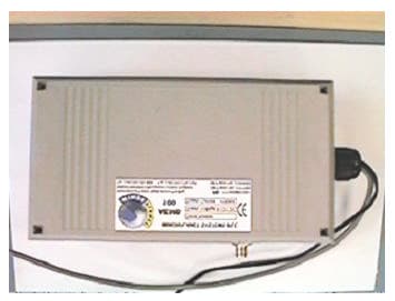
Click to zoom
Application Details
- Equipment Class
- DXT - Part 15 Low Power Transceiver, Rx Verified
- Date of Grant
- Aug 28, 2002
- Application Purpose
- Original Equipment
- Date of Application
- Jul 24, 2002
- Equipment Note
- AVL and Data Logging System
- Frequency Range
- 902.75000000 - 902.75000000
- Company
- Minorplanet Systems PLC
- Country
- United Kingdom
Documents & Files
Document Text
Text extracted from the exhibit documents filed with the FCC. Open a document above to read the original.
Users Manual
MINORPLANET AEMB100 Base Station AVL & Data Logging System System Overview & Installation Guide AEMB100 Base Station WM1003 Issue 1 MINORPLANET 1. OPERATION 1.1 Maptrack System Overview The Maptrack system brings together satellite based global positioning technology, microprocessor control, low power radio and international GSM communication infrastructure to achieve wide area communication, vehicle location, telematics and communication services. 1.1.1 Operation Overview 1.2 System Overview The AEM3000 is an electronic data collection and transmission device, incorporating GPS tracking and GSM communication technologies. Whilst the vehicle is in use, geographical and operational data is continually monitored and recorded within the DCU (data collection unit) memory. Up to 8 weeks of operational data can be held within the DCU. If the memory capacity is reached before the data is downloaded, the oldest records will be lost as new records are recorded. Recorded data may be downloaded for processing by the base computer in the following ways; a) bulk download of all held data via the GSM data channel b) snap shot of current ‘live’ data via the GSM SMS network. c) bulk download of held data via the FCC compliant low power radio interface upon return to base. Interrogation of the DCU is possible anywhere that benefits from GSM network coverage (subject to roaming agreements with GSM networks). AEMB100 Base Station WM1003 Issue 1 MINORPLANET 1.3 System Operation The Maptrack in-vehicle system consists of the DCU (data collection unit), GPS, GSM and Low Power Local Download antennae. Only power and ignition connections are made to the vehicle electrical system. When an ignition signal is present at the DCU the system records a start event and activates the GPS receiver, the vehicles geographical position, velocity and distance travelled are then continually recorded within the DCU until the ignition signal is removed, at which time a stop event is recorded, the DCU then performs any outstanding tasks before powering down the GPS receiver and GSM transceiver. When the vehicles ignition is turned off, the low power radio will power up and transmit a ‘Come And Get Me’ (CAGM) packet. If the vehicle is within range of its AEMB100 Base Station this packet will be received by the Base Station, which will request a transfer of data from the Vehicle to the Base Station. This transfer of data is via the Low Power Radio link in a half-duplex packet format. 1.4 AEMB100 Component Layout AEMB100 PCB Assembly AEMB100 Internal Wiring Radio Packet Controller Detail AEMB100 Base Station WM1003 Issue 1 MINORPLANET 2. SAFETY STANDARDS The AEMB1000 Base Station and associated equipment has been fully EMC tested to VCA recommendations in accordance with European Directive 95/54/EC, Annex 7 & 8 (emissions). 2.1 Low Power Radio Antenna Element The low power radio contained within the AEMB100 Base Station is designed to comply with FCC directive part 15. As such only aerials approved and supplied by Minorplanet may be used in conjunction with this product. It is forbidden to use any antennae other than those verified and approved by Minorplanet. Both the AEMB100 Base Station and its associated antenna must be installed, and/or protected, in such a way that they will be inaccessible to normal pedestrian traffic after installation. 3. TECHNICAL SPECIFICATION Due to continuous product development, aspects of the following specification may be changed without notice and solely at the discretion of the manufacturer. 3.1 Mechanical Specification AEMB100 Base Station Size (mm) : 112 W x 70 H x 200 L . Weight : 400 grams. Material : Two part impact resistant polystyrene. 3.2 Electrical Specification Supply Voltage : 9 to 12 volts DC. Current @ 12V : 120 mA Maximum. LPR Transceiver : 902.75MHz max 1 mW @ 3M, FCC part 15 compliant Operating Temp : -20 to +50 degrees centigrade. EMC : Tested to meet European directive 95/54/EC (emissions). AEMB100 Base Station WM1003 Issue 1 MINORPLANET 3.3 LPR Antenna Specification SPECIFICATIONS Frequency Range 902 – 925 MHz PCS: 1850 - 1980 MHz VSWR <2:1 Vertical 3 dB beamwidth 72° typ Rated Power 10 Watts Impedance 50 ohms Termination N-type female on 1 m Low Loss RG58 cable tail Material Radiator: 7/7 PH stainless steel Cover:: ABS Operating Temperature -20°C to +80°C Mounting With bracket onto wall Antenna Size 150mm high on 55x200mm bracket Packing Weight / Volume 0.2kg / 25 x 20 x 6cm It should be noted that the above information indicates the typical antenna to be used for local download purposes. AEMB100 Base Station WM1003 Issue 1 MINORPLANET AEMB100 Base Station WM1003 Issue 1 4.1 AEMB100 WIRING DIAGRAM F.C.C.CAUTION: THIS DEVICE COMPLIES WITH PART 15 OF THE FCC RULES. OPERATION IS SUBJECT TO THE FOLLOWING TWO CONDITIONS: (1) THIS DEVICE MAY NOT CAUSE HARMFUL INTERFERENCE, AND (2) THIS DEVICE MUST ACCEPT ANY INTERFERENCE RECEIVED, INCLUDING INTERFERENCE THAT MAY CAUSE UNDERSIRED OPERATION. NOTE: NO CHANGES OR MODIFICATIONS MAY BE MADE TO THE UNITS. ANY CHANGES MADE TO THE UNITS WILL VOID THE USER’S AUTHORITY TO OPERATE THE EQUIPMENT.
Block Diagram
AEMB100 Block Diagram INFO.DOCU.0011 MINORPLANET SYSTEMS PLC AEMB100 Base Station Block Diagram Revision History Issue Date Engineer Checked Notes 1 17 th May 2002 M. GjessingJ. Macey First issue. Microprocessor Internal PSU RS232 Converter Personal Computer 902.75MHz Local Download RPC Local Download Antenna External PSU 17 th May 2002 Copyright Minorplanet Systems plc. Unauthorized re production and distribution is prohibited Page 1 of 1
Internal Photos
Christian Pickard Direct line +44 (0) 113 3847145 Mobile +44 (0) 7831 362206 e-mail [email protected]
Operational Description
DSGN.NOTE.3003.0001 Low Power Radio Base Station AEM3000 DSGN.NOTE.3003.0001Copyright Minorplanet Ltd.Page 1 of 2 Unauthorised reproduction and distribution is prohibited MINORPLANET LTD Wa r ni n g – this document is uncontrolled and shall not be used for manufacturing unless it has been stamped and endorsed by the Minorpl anet Quality Department. Low Power Radio Base Station Functional Description 1 Revision History IssueDateEngineerCheckedC/N Notes 101/05/02 C G HarrisonJ S Shaw—Initial issue. 202/07/02 C G HarrisonJ S ShawLPRS modules added 2 Introduction This document describes the basic operation of the low power radio interface used in the Base Station for local download of AEM3000 DCUs. 3 Overview The Minorplanet low power radio base station provides a bi-directional interface between a serial data stream and RF packet transmissions. At the heart of the base station is either a Radiometrix or a Low Power Radio Solutions (LPRS) “Radio Packet Controller” (RPC). The Radiometrix RPC is available in two versions; the RPC-418-40 for the UK and the RPC-433-40 for Europe. The LPRS RPC is also available in two versions; one uses the MP400 (434MHz) for Europe and the other uses the MP900 (902.75 MHz) for the U.S. All four modules are pin-out compatible, are licence exempt and comply with the relevant regulations (MPT1340 and ETSi 300-220). The RPC transmits and receives packets of data which are between 1 and 27 bytes in length. The RPC uses a proprietary parallel interface so a micro-controller is used to convert the serial data to this form (and vice versa for receive). The Base Station is often situated remotely from the controlling computer so two types of serial interface are provided; RS232 and RS485. The block diagram of the Base Station is as follows: Note: For clarity the above block diagram only shows the power supply to the micro-controller. The 9 control signals between the micro-controller and the RPC comprise four bi-directional data lines (D0-D3), two receive control lines (RXR and RXA), two transmit control lines (TXA and TXR) plus a RPCMicro-controller RS232 interface RS485 interface 5V PSU 9 RS232 RS485 12V unregulated DSGN.NOTE.3003.0001 Low Power Radio Base Station AEM3000 DSGN.NOTE.3003.0001Copyright Minorplanet Ltd.Page 2 of 2 Unauthorised reproduction and distribution is prohibited MINORPLANET LTD Wa r ni n g – this document is uncontrolled and shall not be used for manufacturing unless it has been stamped and endorsed by the Minorpl anet Quality Department. reset signal. Refer to the Radiometrix RPC data sheet for pin connection numbers and a complete description of the RPC module operation. 4 Transceiver Operation 4.1 Receive Mode When the base station is idle it is in receive mode. The reset signal is negated and the micro-controller polls the receive request (RXR) line. If the RPC receives a valid packet it places the first four bits of data on the data lines, asserts the RXR signal and waits for the micro-controller to strobe the data out of its buffer. The parallel interface is only 4 bits wide (D0 - D3) so each byte is transferred as two nibbles. Every packet starts with a length byte so that the controller knows how many bytes to strobe from the RPC. The maximum packet size is 27 bytes (or 54 nibbles). When the micro-controller has clocked a packet out of the RPC it transmits the data over the serial interface at 9600 baud to the host computer. 4.2 Tra ns mit Mo de If the base station receives a packet from the host computer via the serial interface it immediately attempts to send it to the RPC by asserting the transmit request signal (TXR). If the RPC is currently decoding a receive packet it will ignore the request until either a valid packet has been received or the current receive process times out. When the RPC is ready to transmit it places the data lines into input mode and asserts the transmit acknowledge signal. The micro-controller can now clock the transmit packet into the RPC via the four data lines one nibble at a time. If the micro-controller fails to clock a complete, valid, packet into the RPC within one second a timeout will occur and the RPC will enter receive mode again. 4.3 RF Connection and LED Indication The RPC uses an SMB connector for the RF connection. The status of the RPC is shown by a red “Tx” LED and a bi-colour “Rx” LED. For more details of the LED indication refer to the Radiometrix data sheet.
Parts List/Tune Up Info
Bill of Materials ELEC.UNIT.B101.0001 UNIT.EBOM.B101.0001 16 May 2002Copyright Minorplanet Ltd.UNIT.EBOM.B101.0001 Unauthorised reproduction and distribution is prohibitedIssue 1 Page 1 of 2 MINORPLANET LTD Wa rning – this document is uncontrolled and shall not be used for manufacturing unless it has been stamped and endorsed by the Minorpl anet Quality Department. Bill of materials for ELEC.UNIT.B101.0001 1 Revision History IssueDateEngineerCheckedC/N Notes 031/01/02 K SinghName—Draft. 116/05/02 K SinghM. Gjessing—Initial Issue 2 Bill of Materials Command Control Centre – Base Station 100 (CCC-B100). DesignatorPart Ty peDescriptionPart Fie ld 1Part Fie ld 2 C1CAP ACITOR33pF 2%COMP.CERC.T001.0330 C2CAP ACITOR33pF 2%COMP.CERC.T001.0330 C3NOT FITTED C4CAP ACITOR10uF 35VCOMP.ALEC.T006.0001 C5CAP ACITOR0.1uF 63VCOMP.POLY.T001.0001 C6CAP ACITOR0.1uF 63VCOMP.POLY.T001.0001 C7NOT FITTED C8CAP ACITOR0.1uF 63VCOMP.POLY.T001.0001 C9CAP ACITOR0.1uF 63VCOMP.POLY.T001.0001 C10CAP ACITOR10uF 35VCOMP.ALEC.T006.0001 C11CAP ACITOR0.1uF 63VCOMP.POLY.T001.0001 D1LEDGreen Ø5mmCOMP.OPTO.T003.0002 D2LEDRed Ø5mmCOMP.OPTO.T003.0001 D3DIODE1N4007COMP.RECT.T002.0001 D4LEDGreen Ø5mmCOMP.OPTO.T003.0002 D1AMECHANICALNylon Spacer 3mmCOMP.MECH.0011.0003 D2AMECHANICALNylon Spacer 3mmCOMP.MECH.0011.0003 D4AMECHANICALNylon Spacer 3mmCOMP.MECH.0011.0003 FS1FUSERest Table Fuse 1.1 AmpereCOMP.PROT.T003.0001 J1CONNECTOR3 way pin headerCOMP.CONN.T008.0A03 J2CONNECTOR3 way pin headerCOMP.CONN.T008.0A03 J1ACONNECTORShorting Link 2.54mm JumperCOMP.RSTR.0001.0001 J2ACONNECTORShorting Link 2.54mm JumperCOMP.RSTR.0001.0001 OSC1CRYSTAL11.059MHzCOMP.XTAL.T002.0003 R1RESISTOR470R 5%COMP.RSTR.T001.0471 R2RESISTOR470R 5%COMP.RSTR.T001.0471 R3RESISTOR8K2 5%COMP.RSTR.T001.0823 R4RESISTOR10K 5%COMP.RSTR.T001.0103 R5RESISTOR100R 5%COMP.RSTR.T001.0101 R6RESISTOR470R 5%COMP.RSTR.T001.0471 REG1REGULATORL7805CVCOMP.PSUA.T001.0001 Bill of Materials ELEC.UNIT.B101.0001 UNIT.EBOM.B101.0001 16 May 2002Copyright Minorplanet Ltd.UNIT.EBOM.B101.0001 Unauthorised reproduction and distribution is prohibitedIssue 1 Page 2 of 2 MINORPLANET LTD Wa rning – this document is uncontrolled and shall not be used for manufacturing unless it has been stamped and endorsed by the Minorpl anet Quality Department. DesignatorPart Ty peDescriptionPart Fie ld 1Part Fie ld 2 REG1AFASTENERNylon Rivet BlackCOMP.FAST.0009.3640 SK1CONNECTORRight Angle 12 pin HeaderCOMP.CONN.T027.0B12 T1CONNECTORRis ing Clamp Interlocking 4 wayCOMP.CONN.0009.0004 T2CONNECTORRis ing Clamp Interlocking 3 wayCOMP.CONN.0009.0003 T3CONNECTORRis ing Clamp Interlocking 3 wayCOMP.CONN.0009.0003 T4CONNECTORRis ing Clamp Interlocking 3 wayCOMP.CONN.0009.0003 T5CONNECTORRis ing Clamp Interlocking 4 wayCOMP.CONN.0009.0004 U1MICRO-CONTROLLER TS87C52X2 40 pin DIPCOMP.PROC.T001.0001 U2RS232RS232 Driver/ Receiver 20 pin DIPCOMP.IFCE.T002.0001 U3RS485Low Power Transceiver 8 pin DIPCOMP.IFCE.T001.0001 U4MicroprocessorSupervisory Circuit 16 pin DIPCOMP.SFIC.T001.0001 U1 ACONNECTORDIP Socket 40 pinCOMP.CONN.T028.0240 U2 ACONNECTORDIP Socket 20 pinCOMP.CONN.T028.0120 U3 ACONNECTORDIP Socket 8 pinCOMP.CONN.T028.0108 U4 ACONNECTORDIP Socket 16 pinCOMP.CONN.T028.0116 RPC/ BIMMODULERadio Packet ControllerCOMP.MODL.0009.0418COMP.MODL.0009.0433 M1FASTENERPan Head Pozidr iv Screw M3 12mmCOMP.FAST.0010.3012 M2MECHANICALFibre Washer M3 RedCOMP.MECH.0009.0030 M3MECHANICALNylon Spacer 3mmCOMP.MECH.0011.0003 M4FASTENERM3 NutCOMP.FAST.0004.0030 M5ASSEMBLYCCC- B100 UHF CableCABL. ASS Y.B100.0001 PCBCIRCUIT BO ARDPrinted Circ uit Board CCC- B100COMP.PCBR. B100.0001 Notes: 1. Part fie ld 2 is to pe rmit d iffe re nt b uild optio ns. Re fe r to spec ified dra wings for de ta ils. 2. Blank fields denote parts not fitted. 3. Part fields separated by horizontal lines may be selected independently of each other.
Parts List/Tune Up Info
Purchase Bill of MaterialsELEC.UNIT.B101.0001UNIT.PBOM.B101.000116 May 2002 Copyright Minor planet Ltd. UNIT.PBOM.B101.0001 Unauthorised reproduct ion and distribution is prohibited Issue 1 Page 1 of 3 MINOR PLANET LTD Purchasing Bill of Materials ELEC.UNIT.B101.0001 1 ] Revision History Issue Date Engineer Checked C/N Notes 0 31/01/02 K Singh — Draft 1 16/05/02 K Singh M. Gjessing - Initial Issue 2 Purchasing Bill of Materials Command Control Centre – Base Station 100 (CCC-B100) REFERENCE DRAWING NUMBER DESCRIPTION CATALOGUE NUMBER QTY MANUFACTURE ALTS C1. C2 COMP.CERC.T001.0330 Ceramic Plate Capacitor 33pF 2% 2222 683 10339 2 Ph ilips SEE COMP.SPEC C4. C10 COMP.ALEC.T006.0001 CAP. EL. 10uF 35V 2222 097 50109 2 BC Components SEE COMP.SPEC C5. C6. C8.C9. C11 COMP.POLC.T001.0001 CAP. 0.1uF 63V 2222 370 75104 5 BC Components SEE COMP.SPEC D1. D4 COMP.OPTO.T003.0002 Vertical LED Green TLH-series 2 Temic SEE COMP.SPEC D2 COMP.OPTO.T003.0001 Vertical LED Red TLH-series 1 Temic SEE COMP.SPEC D3 COMP.RECT.T002.0001 Rectifier 1N4007 1N4007 1 Fairchild SEE COMP.SPEC D1A. D2A.D4A COMP.MECH.0011.0003 Nylon Spacer 3mm N/A 3 N/A SEE COMP.SPEC Purchase Bill of MaterialsELEC.UNIT.B101.0001UNIT.PBOM.B101.000116 May 2002 Copyright Minor planet Ltd. UNIT.PBOM.B101.0001 Unauthorised reproduct ion and distribution is prohibited Issue 1 Page 2 of 3 MINOR PLANET LTD FS1 COMP.PROT.T003.0001 1.1 Ampere Reset table fuse RUSB110 1 Raychem SEE COMP.SPEC J1. J2 COMP.CONN.T008.0A03 3 way pin headers N/A 2 N/A SEE COMP.SPEC J1A. J2A COMP.RSTR.0001.0001 Shorting link 2.54mm Jumper M7564-05 2 Harwin SEE COMP.SPEC OSC1 COMP.XTAL.T002.0003 AT Cut Quartz Crystal 11.059MHz 11.059HC-79/S 1 AEL SEE COMP.SPEC R1. R2. R6 COMP.RSTR.T001.0471 470R 5% resistor MF25 series 3 Multicomp SEE COMP.SPEC R3 COMP.RSTR.T001.0823 8K2 5% resistor MF25 series 1 Multicomp SEE COMP.SPEC R4 COMP.RSTR.T001.0103 10K 5% resistor MF25 series 1 Multicomp SEE COMP.SPEC R5 COMP.RSTR.T001.0101 100R 5% resistor MF25 series 1 Multicomp SEE COMP.SPEC REG1 COMP.PSUA.T001.0001 Positive Voltage Regulator L7805CV 1 ST SEE COMP.SPEC REG1A COMP.FAST.0009.3640 Nylon Rivet Black Series SR/SRVO 1 Richco SEE COMP.SPEC SK1 COMP.CONN.T027.0B12 Right Angle 12 pin Header 42153 series 1 Molex SEE COMP.SPEC T1. T5 COMP.CONN.0009.0004 Rising Clamp Interlocking 4 way 8191 series 2 Wieland SEE COMP.SPEC T2. T3. T4 COMP.CONN.0009.0003 Rising Clamp Interlocking 3 way 8191 series 3 Wieland SEE COMP.SPEC U1 COMP.PROC.T001.0001 Micro Controller 40 pin DIP TS87C52X2-MCA 1 Amtel Wireless SEE COMP.SPEC U2 COMP.IFCE.T002.0001 RS232 Driver/ Receiver 20 pin DIP MAX233CPP 1 Maxim SEE COMP.SPEC U3 COMP.IFCE.T001.0001 Low Power Transceiver 8 pin DIP MAX485CPA 1 Maxim SEE COMP.SPEC U4 COMP.SFIC.T001.0001 Microprocessor 16 pin DIP PMAX691CPE 1 Maxim SEE COMP.SPEC Purchase Bill of MaterialsELEC.UNIT.B101.0001UNIT.PBOM.B101.000116 May 2002 Copyright Minor planet Ltd. UNIT.PBOM.B101.0001 Unauthorised reproduct ion and distribution is prohibited Issue 1 Page 3 of 3 MINOR PLANET LTD U1A COMP.CONN.T028.0240 DIP Socket 40 pin N/A 1 N/A SEE COMP.SPEC U2A COMP.CONN.T028.0120 DIP Socket 20 pin N/A 1 N/A SEE COMP.SPEC U3A COMP.CONN.T028.0108 DIP Socket 8 pin N/A 1 N/A SEE COMP.SPEC U4A COMP.CONN.T028.0116 DIP Socket 16 pin N/A 1 N/A SEE COMP.SPEC RPC/BIM COMP.MODL.0009.0418 COMP.MODL.0009.0433 Radio Packet Controller UKRadio Packet Controller EURO RPC-418-40: IC+BIMRPC-433-40: IC+ BIM 11 RadiometrixRadiometrix M1 COMP.FAST.0010.3012 Pan Head Pizdriv Screw M3 12mm N/A 1 N/A SEE COMP.SPEC M2 COMP.MECH.0009.0030 Fibre Washer Red M3 N/A 1 N/A SEE COMP.SPEC M3 COMP.MECH.0011.0003 Nylon Spacer 3mm N/A 1 N/A SEE COMP.SPEC M4 COMP.FAST.0004.0030 Nut M3 N/A 1 N/A SEE COMP.SPEC M5 CABL.ASSY.B100.0001 CCC-B 100 UHF Cable N/A 1 N/A SEE COMP.SPEC PCB COMP.PCBR.B100.0001 Printed Circuit Board CCC-B100 N/A 1 N/A SEE COMP.SPEC
Test Report
FCC ID: QDAAEMB100 Retlif Report Number R-9469 APPLICANT Minorplanet Systems PLC Shaweld House Benson Street Leeds, United Kingdom LS7 1BL Manufacturer Minorplanet Systems PLC Shaweld House Benson Street Leeds, United Kingdom LS7 1BL TEST SPECIFICATION:FCC Rules and Regulations Part 15, Subpart C TEST PROCEDURE:FCC 15.249(a) TEST SAMP LE DESCRIP TION BRANDNAME:Minorplanet Systems PLC MODEL:AEMB100FCC ID: QDAAEMB100 TYPE:Pulse Modulated Transmitter FREQUENCY RANGE:902.75 MHz POWER REQUIREMENTS: 12 VDC TESTS P ERFORMED - 15.209(c)Radiated Emissions, Spurious Case - 15.249(a)Radiated Emissions, Fundamental and Harmonics - 15.249(c)Occupied Bandwidth - 15.35(a)Duty Cycle Determination FCC ID: QDAAEMB100 Retlif Report Number R-9469 REPORT OF MEASUREMENTS Applicant:Minorplanet Systems PLC Device:Pulsed RF Transmitter FCC ID:QDAAEMB100 Power Requirements:12 VDC Applicable Rule Section:Part 15, Subpart C, Section 15.249 TEST RESULTS 15.209(a):Field strength of emissions from the intentional radiator operating in the 902 MHz to 928 MHz GHz frequency band did not exceed 50 mV/m quasi-peak for the fundamental and 500 uV/m average for harmonics. 15.249(b):Field strength readings were recorded at a distance of three meters from the Intentional Radiator unless otherwise specified. 15.249(c):Emissions radiated outside the specified frequency band except for harmonics, were attenuated by at least 50dB or to the emissions limits of 15.209, whichever was the lesser attenuation. 15.249(d):All measurements were taken utilizing a peak detector. The peak field strength did not exceed the average limits under any condition of modulation. Duty Cycle Information: The EUT has on time of 37 mSec (worst case) in any 100 mSec period. This yields a duty cycle of 37% or a duty cycle factor of -8.6dB. See also attached plots named dutycycle.pdf. FCC ID: QDAAEMB100 Retlif Report Number R-9469 SPECTRUM ANALYZER DESENSITIZATION CONSIDERATIONS Due to the nature of the emissions being measured, care was taken to ensure that the resolution bandwidth of the spectrum analyzer was adequate to provide accurate measurements. The following formula was utilized: Setting pulse desensitization equal to zero and utilizing the minimum observed pulse width of 37 mSec yields a minimum required bandwidth of 18 Hz. FCC specified bandwidths of 100kHz and 1MHz were utilized below and above 1GHz, respectively. GENERAL NOTES 1.All user accessible controls were adjusted to produce maximum emissions. 2.The unit operates in the band of 902 MHz to 928 MHz GHz band at a single frequency of 902.75 MHz. 3.The frequency range was scanned from 30 MHz to 9.1 GHz. All emissions not reported were more than 10dB below the specified limit. FCC ID: QDAAEMB100 Retlif Report Number R-9469 EXHIBIT 4 Radiated Emissions, Spurious Case Para. 15.249(c) (Please see separate e-file attachment named RESpur.pdf) FCC ID: QDAAEMB100 Retlif Report Number R-9469 EXHIBIT 4 Radiated Emissions, Fundamental & Harmonic Para. 15.249(a) (Please see separate e-file attachment named REfundharm.pdf) FCC ID: QDAAEMB100 Retlif Report Number R-9469 EXHIBIT 4 Occupied Bandwidth Para. 15.249(c) (Please see separate e-file attachment named OccBw.pdf) FCC ID: QDAAEMB100 Retlif Report Number R-9469 EXHIBIT 4 Duty Cycle Determination Para. 15.35 (Please see separate e-file attachment named dutycycle.pdf) FCC ID: QDAAEMB100 Retlif Report Number R-9469 EQUIPMENT LIST FCC 15.249 Compliance Testing ENTypeManufacture rDe scriptionMode l No.Cal Date Due Date 067Open Area Test SiteRetlif3 MeterRNY9/20/009/20/03 128Double Ridged GuideElectro-Mechanics1 GHz - 18 GHz31056/7/026/7/03 133Broadband Pre-AmplifierElectro-Metrics10 kHz - 1 GHz, 26dBBPA-10006/11/026/11/03 141Spectrum AnalyzerHewlett Packard100 Hz - 40 GHz8566B7/17/021/17/03 141AGraphics PlotterHewlett PackardN/A7470A3/5/023/5/03 141BQuasi-Peak AdaptorHewlett Packard100 Hz - 1 GHz85650A7/16/021/16/03 206B6.0 dB AttenuatorTexscan0 - 1.0 GHzFP-50 - 6 dB6/11/026/11/03 543PreamplifierHewlett Packard1.0 GHz - 26.5 GHz8449B7/11/027/11/03 767BiconilogEMCO26 - 2000 MHz3142B8/28/018/28/02 FCC ID: QDAAEMB100 Retlif Report Number R-9469 Test Setup Photograph
Test Setup Photos
FCC ID: QDAAEMB100 Retlif Report Number R-9469 TEST SETUP PHOTOGRAPH
Contact Information
Applicant
Mark Gjessing(Quality Manager)
Technical Contact
Retlif Testing LaboratoriesThomas J Schneider
[email protected]631-737-1500
795 Marconi Avenue · Ronkonkom, New York · United States
Non-Technical Contact
Retlif Testing LaboratoriesMichelle White
[email protected]631-737-1500
Test Firm
Retlif Testing LaboratoriesMichael Bozza
Technical Specifications
| # | Rule Parts | Frequency Range | Power Output |
|---|---|---|---|
| 1 | 15C | 902.75 MHz - 902.75 MHz | - |
Other Applications from Minorplanet Systems PLC
QDAAEM3000DCU
Jul 18, 2002AVL and Data Logging System
Equipment Class
DXX - Part 15 Low Power Communication Device Transmitter