QDMAK100Portable Music Player
DREAMUS COMPANY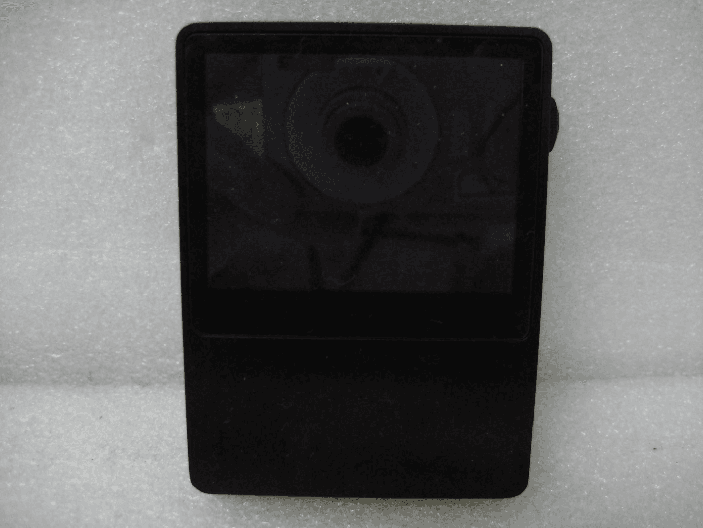
Click to zoom
Application Details
- Equipment Class
- DSS - Part 15 Spread Spectrum Transmitter
- Date of Grant
- Oct 25, 2012
- Application Purpose
- Original Equipment
- Date of Application
- Oct 25, 2012
- Equipment Note
- Portable Music Player
- Frequency Range
- 2402.00000000 - 2480.00000000
- Company
- DREAMUS COMPANY
- Country
- South Korea
Documents & Files
Document Text
Text extracted from the exhibit documents filed with the FCC. Open a document above to read the original.
Users Manual
INSTRUCTION BOOK 제품 사용 설명서 Components Names of parts Power supply management Connecting Using iriver plus4 02 02 04 05 09 Getting Started _01 Basic operations Listening to the music Using Bluetooth Settings 13 13 15 17 Using _02 Safety cautions Problem solving Copyright Certification Registered trademark Escape clause 19 20 21 22 22 22 Other information _03 CONTENTS User Guide AK100 Quick start guide & product warranty Micro USB cable Micro USB cable: You can connect the product to the computer and charge it. Quick start guide: It describes the basic method of using the product. Product warranty: Please keep the product warranty in a safe place in the event your iriver device needs servicing. Manual: Please read the manual (pdf file) saved as a PDF file in the product before use. Components may be changed without notice to improve the performance or quality of the product. Compo- nents Product appearance, printed and engraved information may vary depending on the model. Names of parts Earphone / OPTICAL OUT terminal Power Micro SD card slot OPTICAL IN terminal Micro USB terminal Getting Started 02 Play/Pause Next/ Fast forward Previous/ Rewind Volume Touch LCD Earphone / OPTICAL OUT terminal: Connect the earphone and output sound through the earphone. Use an optical cable to play music stored in the product on an external device capable of SPDIF-IN. Power: Short - Turn on and off the screen. Long - Turn on and off the product. OPTICAL IN terminal: Use an optical cable to play music stored in an external device capable of SPDIF- OUT on the product. Micro SD card slot: Insert a Micro SD card into the product to see its stored files. Micro USB terminal: Connect the product to the computer or charge it. Previous/Rewind: Short - Replay previous music. Long - Rewind. Play/Pause: Short - Play/pause. Long - Display the playback screen. Next/Fast forward: Short - Play the next music. Long - Fast forward. Volume: Turn the wheel to adjust the volume. Touch LCD: Display the screen, and touch the screen to start. User Guide Getting Started 03 User Guide This product has an automatic power saving function to prevent excessive battery consumption. If there is no key operation within the prescribed period [Settings - power settings - automatically turn off], the iriver device will be automatically turned off. (See page XX) This product has an automatic screen off function to prevent excessive battery consumption. According to the [Settings - power settings - turn off the screen] setting, the screen will be automatically turned off if there is no key operation within the prescribed period. (See page XX) When using the reset function, the current time and memory data will not be deleted. Do not use the reset function while the product is in use. Doing so may seriously damage the memory. Turn on/off the screen 1. When on standby, press and hold the [ ] key to turn off. 2. Press the [ ] key once briefly to turn on the screen. Using the reset function 1. If the product should stop unexpectedly during operation and the keys no longer function normally, press the [ ] key and [ ] key simultaneously > 7 seconds to reset the product. Turn on/off 1. Press and hold the [ ] key to turn on. 2. When on standby, Press and hold the [ ] key to turn off. Power source manage- ment Getting Started 04 Connecting Connecting the earphone 1. Connect the earphone to the earphone terminal of the product. Connecting to a computer 1. Turn on the product and computer. 2. When using a Micro USB cable to connect the product and the computer, the connection mode selection window will be displayed on the screen. - Charging & playing: The iriver device can function normally while being recharged. User Guide Use only the Micro USB cable provided with the product to ensure safe operation. Check that it is connected to a high-power USB 2.0 port. Connecting to a low-power USB port (some keyboards, USB hubs without their own power supply, etc.), may prevent normal charging. Once the computer goes into standby mode, the iriver device may not be charged. The charging time is about 5 hours and 30 minutes. (Fully discharged, with power off) Charge the product while it is turned off. When charging during operation, the full charge display may not be shown. Using the product during charging may require additional time for a full charge or the battery may not fully recharge. Charge and keep the product at room temperature. Exposure to excessive heat or cold may adversely affect charging performance. Battery performance may decline with age and number of recharges. Charging 1. Turn on the computer. 2. Using a Micro USB cable to connect the product to the computer automatically recharges the built-in battery. Getting Started 05 User Guide Disconnecting from a computer 1. Click the icon displayed in the task bar of the computer screen to safely remove it. 2. Click [OK] to ensure the iriver device can be safely removed. An icon may be hidden in the task bar depending on the operating system like Windows XP. Click the icon to display it on the screen. When using application programs like Windows Explorer or Windows Media Player, it may be unsafe to remove the iriver device. Only remove the iriver device after exiting all application programs. Failure to do so may result in loss of stored data. Connect the computer and the iriver device when all functions are stopped. Use only the Micro USB cable provided with the product to ensure safe operation. Connect the computer and the Micro USB cable only after all functions have been stopped. Check that it is connected to a high-power USB 2.0 port. Connecting to a keyboard or a USB hub without its own power supply may prevent normal operation. Only FAT32 file system is supported so format the iriver device accordingly. - Connect a removable disk: It can transmit data while connected to a computer. Getting Started 06 Please connect the Micro USB cable correctly. Use caution when copying or moving files. If the com…
Text truncated - open the document above for the full version.
Users Manual
FCC ID: QDMAK100 FCC INFORMATION This device complies with Part 15 of the FCC Rules. Operation is subject to the following two conditions: 1. This device may not cause harmful interference, and 2. This device must accept any interference received, including interference that may cause undesired operation. Note: This equipment has been tested and found to comply with the limits for a Class B digital device, pursuant to part 15 of the FCC Rules. These limits are designed to provide reasonable protection against harmful interference in a residential installation. This equipment generates, uses and can radiate radio frequency energy and, if not installed and used in accordance with the instructions, may cause harmful interference to radio communications. However, there is no guarantee that interference will not occur in a particular installation. If this equipment does cause harmful interference to radio or television reception, which can be determined by turning the equipment off and on, the user is encouraged to try to correct the interference by one or more of the following measures: —Reorient or relocate the receiving antenna. —Increase the separation between the equipment and receiver. —Connect the equipment into an outlet on a circuit different from that to which the receiver is connected. —Consult the dealer or an experienced radio/TV technician for help. Caution: Any changes or modifications not expressly approved by the party responsible for compliance could void the user's authority to operate this equipment.
Cover Letter(s)
FCC Confidentiality Request Number: CF303 Version: V05 Date: 21-05-2012 (Permanent or also called long term confidentiality is the normal method to keep certain docuements confidential, and may apply to schematics, block diagrams, operational description and bill of materials.) To: Federal Communications Commission Equipment Authorization Branch 7435 Oakland Mills Road Columbia, MD 21046 Pursuant to 47 CFR Section 0.459(a) & (b), we, (the applicant / grantee) Company name IRIVER LIMITED. Address Iriverhouse, 902-5, Bangbae-dong, Seocho-gu, City Seoul Country Republic of Korea request for this certification filing under: Grantee Code Product Number FCC ID: QDM AK100 to maintain permanent confidentiality for the following documents submitted within this application: (please cross what is applicable, or add other documents, provide the file name and description) 1. Schematics 2. Parts List 3. Block Diagram Above materials crossed contain secrets, proprietary and technical information, which would customarily be guarded from competitors under 47 CFR, section 0.457(d)(2). Disclosure or publication or any portion of this company confidential material to other parties could cause substantial competitive harm and provide unjustified benefits for competitors. We understand that pursuant to 47 CFR section 0.457(d)(1)(ii) disclosure of the applicant and all accompanying documentation will not be made before the date of the grant. The documents indicated as confidential above, are not publicly available elsewhere. Attestation: City and Country: Date: Name of client: (this must be a person) Function: Signature: (or official company stamp) Seoul, Korea 2012-10-22 Woo-Suk, Kim Manager
Cover Letter(s)
FCC Short Term Confidentiality Request Number: CF313 Version: V01 Date: 21-05-2012 (With Short term confidentiality, a period of max. 180 days on certain additional exhibits are possible, such as internal/external photos, user manual can test setup photosbet. After expiration of the confidentiality period, these additional exhibits for short term confidentiality become visible in the FCC database for the internet public.) To: Federal Communications Commission Equipment Authorization Branch 7435 Oakland Mills Road Columbia, MD 21046 Pursuant to 47 CFR Section 0.459(a) & (b), we, (the applicant / grantee) Company name IRIVER LIMITED. Address Iriverhouse, 902-5, Bangbae-dong, Seocho-gu, City Seoul Country Republic of Korea request for this certification filing under: Grantee Code Product Number FCC ID: QDM AK100 to maintain short term confidentiality for a period of 180 days for the following documents submitted within this application: (please cross what is applicable, or add other documents, provide the file name and description) 1. Internal Photos, Ex ternal Photos 2. Test Setup Photo Above materials crossed contain secrets, proprietary and technical information, which would customarily be guarded from competitors under 47 CFR, section 0.457(d)(2). Disclosure or publication or any portion of this company confidential material to other parties could cause substantial competitive harm and provide unjustified benefits for competitors. We understand that pursuant to 47 CFR section 0.457(d)(1)(ii) disclosure of the applicant and all accompanying documentation will not be made before the date of the grant. The documents indicated as confidential above, are not publicly available elsewhere. Attestation: City and Country: Date: Name of client: (this must be a person) Function: Signature: (or official company stamp) Seoul, Korea 2012-10-22 Woo-Suk, Kim Manager Test Setup Photo, U ser ManualTest Setup Photo, U ser Manual
ID Label/Location Info
Label and Label Location located at the backside of the device: FCC ID: QDMAK100 This device complies with Part 15 of the FCC Rules. Operation is subject to the following two conditions: 1. This device may not cause harmful interference, and 2. This device must accept any interference received, including interference that may cause undesired operation.
Parts List/Tune Up Info
Confidential Application Report Amotech / Antenna Gr. Customized Confidential Customer 아이리버 Model TD100 Application Bluetooth Antenna type FPCB+Cable Ass’y Type Report No. #2-1 Date 2012. 07. 16 Written by : 정 훈 Contact : [email protected] Confidential 2 1. Summary of the antenna test 1) Test Condition 2) Radiation Gain Table Test No Antenna Type Condition #2-1 FPCB+Cable Ass’y Type SET Matching (Series = 0Ω) Test No Freq (GHz) Efficiency (%) Avg. Gain (dBi) Peak Gain (dBi) #2-1 2400 MHz 30.3 -5.2 0.9 2442 MHz 32.0 -5.0 2.4 2485 MHz 24.8 -6.1 2.2 Confidential 3 3) Remark #2-1 : 최종 Rear Case 적용 Sample 안테나 Pattern 3.0mm Cut Confidential 4 Test No. #2-1 Antenna FPCB+Cable Ass’y Series 0Ω 1) 안테나 Layout 및 S-Parameter 2. TEST #2-1 Confidential 5 Test No Freq (GHz) Efficiency (%) Avg. Gain (dBi) Peak Gain (dBi) #2-1 2400 MHz 30.3 -5.2 0.9 2442 MHz 32.0 -5.0 2.4 2485 MHz 24.8 -6.1 2.2 2. TEST #2-1 2) Radiation Gain x y z θ φ -x
RF Exposure Info
FCC RF Exposure EUT Description: Portable Music Player Company: IRIVER LIMITED. Model: AK100 FCC ID: QDMAK100 Frequency: 2402-2480 MHz (79 channels) Modulation: FHSS (GFSK, 8DPSK, Pi/4 DQPSK) Mid-Channel: 2.441 GHz (channel 39) Mid-Channel Peak Power, Conducted: 3.63 dBm == 2.31 mW Antenna Gain: G = 2.4 dBi Calculation: Limit = 60/2.441 = 24.58 mW P radiated, max = P conducted, dBm + G dBi = 3.63 dBm + 2.4 dBi == 6.03 dBm = 4.01 mW Conclusion: The emitted power appears to be (far) below the required limit, so PASS. Note 1: f shall be the mid-band frequency expressed in GHz; the limit calculated with this mid-band frequency applies to all channels. For PTT with body-worn or face-held modes, d is the distance from the device case to a parson’s body; for modules with antennas inside laptops, d is the distance from the antenna to the person’s body. Note 2: Average Power levels are always equal or below the measured Peak Power levels, which means that calculating the EIRP using the Peak power can be considered as worst case.)
Test Report
IST Co., Ltd EMC LABORATORY TEST REPORT NO. : 12-IST-0000 1 of 33 CERTIFICATION TEST REPORT FCC CFR47 Part 15 Subpart C Test Report File No. 12-IST-0592 ■ Basic □ Alternate Date of Receipt August 27, 2012 Begin of test date September 10, 2012 Date of Issue October 19, 2012 End of test date September 21, 2012 Kind of Product Portable Music Player Model(s) AK100 FCC ID QDMAK100 Applicant IRIVER LIMITED. Address iriverhouse, 902-5, Bangbae-dong, Seocho-gu, Seoul, Korea Manufacturer IRIVER LIMITED. Address iriverhouse, 902-5, Bangbae-dong, Seocho-gu, Seoul, Korea Test Result ■ Positive □ Negative Tested By Reviewed By B.O. KO. S.J.CHO Comment(s) - Investigations requested : Measurement to the relevant clauses of FCC rules and regulations Part 15 Subpart C. - The test report is consists of 33 pages. - The test result only responds to the tested sample. - It is not allowed to copy this report even partly without the allowance of IST Co., Ltd. - This equipment as for has been shown to be capable of continued compliance with the applicable technical standards as indicated in the measurement report and was tested in accordance with the measurement procedures specified in ANSI C63.4 I assume full responsibility for accuracy and completeness of these data. IST Co., Ltd EMC LABORATORY TEST REPORT NO. : 12-IST-0000 2 of 33 TABLE OF CONTENTS Table of contents 2 Information of test laboratory, Measurement Uncertainty, Product information 3 Descriptions of Test 4 - Conducted Emission 4 - Radiated Emission 5 - Radiated Emission, 9KHz to 30MHz(Magnetic Field Test) 5 Equipment Under Test 6 Summary 7 - - Radiated Emission Peak power output 8~13 14~16 - Band edge 17~20 - Frequency Separation/Occupied Bandwidth 21~27 - Number of hopping frequency 28~92 - Time of occupancy(Dwell time) 30~32 - Antenna requirements 33 Note: IST Co., Ltd EMC LABORATORY TEST REPORT NO. : 12-IST-0000 3 of 33 INFORMATIONS OF TEST LABORATORY EMC LABORATORY of IST Co., Ltd. 400-19, Singal-dong, Giheung-gu, Yongin-si, Kyonggi-Do, 446-599, Korea TEL: +82 31 326 6700 FAX: +82 31 326 6797 Measurement Uncertainty Conducted Emissions U = 2.98 [dB] (Confidence level approximately 95 %, k = 2) Radiated Emissions (Antenna - Horizontal) U = 3.83 [dB] (Confidence level approximately 95 %, k = 2 ) Radiated Emissions (Antenna - Verical) U = 4.50 [dB] (Confidence level approximately 95 %, k = 2 ) PRODUCT INFORMATION Test Mode : Mode 1: Transmit(DH5) Mode 2: Transmit(3DH5) 1. DH5 is for GFSK modulation, and 3DH5 is for Pi/4 DQPSK 2. Regards to the frequency band operation; the highest that was included the lowest, middle and highest frequency of channel were selected to perform the test, and then shown on this report. - Please refer to user’s manual. VCCI Registration No. : 1739 FCC Registration No. : 400603 KCC Registration No. : KR0018 KOLAS Registration No. : KT118 Item Specification Bluetooth Frequency Range 2402 ~ 2480 MHz Modulation Technique FHSS Data Rate 1Mbps(GFSK), 2Mbps(8DPSK), 3Mbps(Pi/4 DQPSK) Number of Channel 79 EA Antenna/Gain FPCB Antenna / 2.4 dBi Operating Voltage DC 3.7V(Battery) Dimensions 59.2 * 79 * 14.4 Weight 122g IST Co., Ltd EMC LABORATORY TEST REPORT NO. : 12-IST-0000 4 of 33 Radiated Emissions: The measurement was performed over the frequency range of 30MHz to 1GHz using antenna as the input transducer to a Spectrum analyzer or a Field Intensity Meter. The measurement was made with the detector set for "quasi-peak" within a bandwidth of 120kHz. Procedure of Test Preliminary measurements were made at 3 meter using bi-log antennas, and spectrum analyzer to determine the frequency producing the max. emission in anechoic chamber. Appropriate precaution was taken to ensure that all emission from the EUT were maximized and investigated. The system configuration, mode of operation, turn-table azimuth and height with respect to the antenna were noted for each frequency found. The spectrum was scanned from 30MHz to 1000MHz using bi-log antenna. Above 1GHz, linearly polarized double ridge horn antennas were used. Final measurements were made at open site with 3- meters test distance using bi-log antenna or horn antenna. The OATS have been verified in regular for its normalized site attenuation. The test equipment was placed on a wooden table. Sufficient time for the EUT, peripheral equipment, and test equipment was allowed in order for them to warm up to their normal operating condition. Each frequency found during pre-scan measurements was re-examined by manual. The detector function was set to CISPR quasi-peak mode and the bandwidth of the receiver was set to 120kHz or 1MHz depending on the frequency of type of signal. The EUT, peripheral equipment and interconnecting cables were re-configured to the set-up producing the max. emission for the frequency and were placed on top of a 0.8-meter high nonmetallic 1 x 1.5 meter table. The EUT, peripheral equipment, and interconnecting cables were re-arranged and manipulated to maximize each emission. The turntable containing the system was rotated; the antenna height was varied 1 to 4 meters and stopped at the azimuth or height producing the maximum emission. Each emission was maximized by: varying the mode of operation to the EUT and/or peripheral equipment and changing the polarity of the antenna, whichever determined the worst-case emission.(The bandwidth below 1GHz setting on the field strength meter is 120KHz and above 1GHz is 1MHz.) IST Co., Ltd EMC LABORATORY TEST REPORT NO. : 12-IST-0000 5 of 33 Radiated Emissions Test, 9 kHz to 30 MHz(Magnetic Field Test) 1. The preliminary radiated measurements were performed to determine the frequency producing the maximum emissions at a distance of 3 meters according to Section 15.31(f)(2). 2. The EUT was placed on the top of the 0.8-meter height, 1 x 1.5 meter non-metallic table. 3. Emissions from the EUT are maximized by adjusting the orientation of the Loop antenna and rotating the EUT on the turntable. Manipulating the system cables als…
Text truncated - open the document above for the full version.
Contact Information
Applicant
HONGGYU LEE(Manager)
Technical Contact
Test Firm
IST Co., LtdCho Sung Jung
Technical Specifications
| # | Rule Parts | Frequency Range | Power Output |
|---|---|---|---|
| 1 | 15C | 2.40 GHz - 2.48 GHz | 2.30 mW |
Other Applications from DREAMUS COMPANY
QDMPPF43
Aug 28, 2024SP3000M
Equipment Class
NII - Unlicensed National Information Infrastructure TXQDMPPM45
Oct 17, 2023KANN ULTRA
Equipment Class
NII - Unlicensed National Information Infrastructure TX
QDMPPR51
May 07, 2023SE300
Equipment Class
NII - Unlicensed National Information Infrastructure TX
QDMPSP22
May 04, 2023UW100 MK II
Equipment Class
DSS - Part 15 Spread Spectrum Transmitter
QDM-HERO-OLS01
Jan 16, 2023LIM YOUNG WOONG OFFICIAL LIGHT STICK
Equipment Class
DTS - Digital Transmission System