QDZDF-5000Digital Video Recorder Card
SEDO Co., Ltd.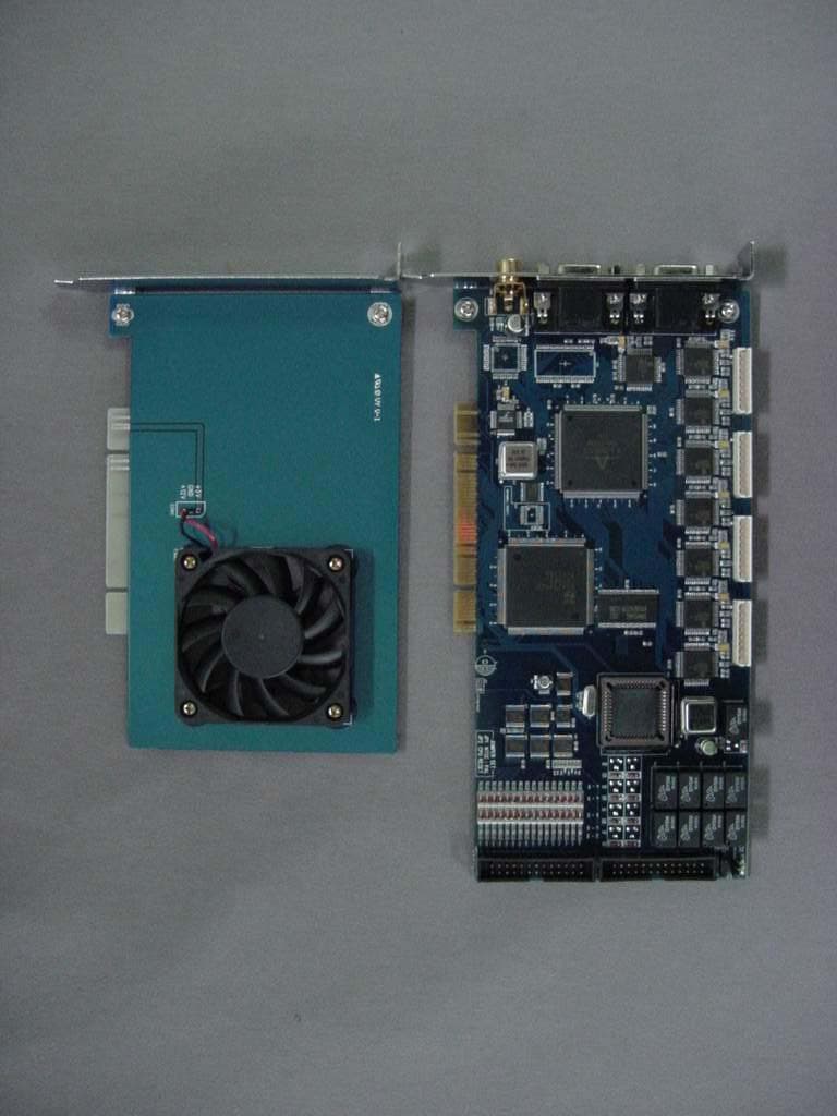
Click to zoom
Application Details
- Equipment Class
- JBP - Part 15 Class B Computing Device Peripheral
- Date of Grant
- Nov 24, 2003
- Application Purpose
- Original Equipment
- Date of Application
- Nov 24, 2003
- Equipment Note
- Digital Video Recorder Card
- Company
- SEDO Co., Ltd.
- Country
- South Korea
Documents & Files
Document Text
Text extracted from the exhibit documents filed with the FCC. Open a document above to read the original.
Users Manual
1 DVR SYSTEM User’s Manual Manual Revision : Version 3.0 Release Date : Aug. 30, 2003 ■SERVER ■CLIENT INFORMATION TO THE USER (Part 15.105(b)) INFORMATION TO THE USER This equipment has been tested and found to comply with the limits for a Class B digital device, pursuant to part 15 of the FCC Rules. These limits are designed to provide reasonable protection against harmful interference in a residential installation. This equipment generates, uses and can radiate radio frequency energy and, if not installed and used in accordance with the instructions, may cause harmful interference to radio communications. However, there is no guarantee that interference will not occur in a particular installation. If this equipment does cause harmful interference to radio or television reception, which can be determined by turning the equipment off and on, the user is encouraged to try to correct the interference by one more of the following measures: -Reorient or relocate the receiving antenna. -Increase the separation between the equipment and receiver. -Connect the equipment into an outlet on a circuit different from that to which the receiver is connected. -Consult the dealer or an experienced radio/TV technician for help. WARNING (Part 15.21) The manufacturer is not responsible for any Radio or TV interference caused by unauthorized modifications to this equipment. Such modifications could void the user’s authority to operate the equipment.” 2 INDEX DVR User’s Manual 1. DVR Sever 1-1. Display Mode Main screen Pan/Tilt Control 1-2. Setup Mode Standard Setup Recoding Setup Schedule setup Motion Detection Setup Color Setup PAN/TILT Setup Network Setup Backup Setup 1-3. Search Mode Search screen Data Back up Search Data & Time Print 2. Client program 3 1. DVR SERVER 1-1. Display mode 4 DISPLAY Mode B E JK A . Camera Number/recording state ( : Camera No. / : Recording / : Motion / : Sensor ) B . Display present images C C . . Select screen division Select screen division among 1/4/6/7/8/9/10/13/16Ch. D. Auto switching (Rotation) : Displays switching images by 1Ch./4Ch./8Ch. in sequence with selected time interval. E. Select camera No. F . Go to ‘SETUP’Mode. G . Go to ‘SEARCH’Mode. H. Power When you click the Power button, DVR system will be shut down. When you want to go Window mode, Please go to Setup. (But, Do not use this function except only unavoidable situation for the system.) I I . . TIME TIME : Display current time. : Display current time. FG A C D H I LM 5 감시 모드 J 1 2 3 45 1 Display information of System For example, VGA card, OS, network communication state etc. 2 Capacity of HDD 3 Calculate used HDD space of current setting. Used HDD space is very changeable by setup of channel, recording method, compressor, image size etc. So, you can calculate used HDD space by this function. Also, If you specified HDD space, you can calculate used HDD space. 4 UPDATE information –Information of adding function & bug fix, etc. 6 5 Printed calculated frame result by each CODEC. ! No data record during compression test. When you click the Power button, DVR system will be shut down. When you want to go Window mode, Please go to Setup. 7 K Display present recording images. • • This function is only our product This function is only our product ’ ’ s special feature. s special feature. You can know present compressed recording image You can know present compressed recording image by CODEC. by CODEC. L Real time chatting between SERVER and CLIENT. If you connect with several user, you can choose just one user and then send message to one user. M Record history of DVR SERVER. You can know working history and Connect history from outside 8 PAN/TILT Control Speed dome control N. PAN/TILT control : Click to active Pan/Tilt control panel. Change direction with direction keys ZOOM : Zoom In / Out. Focus : Control Focus. Speed dome control ( Refer the next page) 4 N 1 2 3 N Click ! 1 2 3 4 M CONTROL moving speed and ZOOM/FOCUS Operation speed of PANTILT camera. But, camera has to include this function. ! Some camera has no P/T, Z/F & preset function. Please use, after check CAMERA MAKER about this function supporting. 9 DISPLAY Mode : Setup Preset of Speed Dome Camera. Speed dome control 1. 4 How to set Preset How to set Preset 1. Select Preset No. 2. Insert Preset ID. 3. Click to save ID. 4. Select a desired place for preset by pan/tilt control panel. 5. Click to add the preset. 6. Click to perform preset. 7. Click to delete preset. 5 3 2 1 6 7 1 2 3 4 4 7 10 DISPLAY Mode Close this Box Run a Group Stop a Group Delete a Group Delete a Preset 123 4 5 67 8 9 2. Rename a Group Insert a Preset between lists Add a Preset How to set a Group 1. Select Group No. 2. Insert Group Name 3. Click to add Group List on . 4. Select Preset No. You can test preset by Click . 5. Select Moving time to next position. 6. Enter Dwell time for the position. 7. Repeat No.1~6 to add group. 8. Select a desired group on and click to run a Group. 9. Click to stop a Group. 5 6 7 4 1 2 34 11 M In case that more than one PTZ camera set up, when user clicks or operates keys of PANTILT, some camera which are operated will be displayed on screen. If click this part, window for PANTILT setting will be open. This function is convenient for users to operate several PANTILT in one DVR system. 12 1. DVR SERVER 1-2. Setup mode 13 STANDARD SETUP go to“SETUP”mode 1. STANDARD setup : after system installation, setup as user’s requires. E 2 4 5 67 8 9 11 10 3 112 13 1. Camera name : Check it to display camera name on screen. 2. Voice : Check it for recording the voice MIC -1CH : Check it for voice recording of channel no.1. 1) Connect to MIC IN. 2) Use after check box of Voice. LINE : When use both communication between SERVER and CLIENT/ 1) Connect to sound CARDLINE IN of SERVER SYSTEM 2) Use after check box of LINE 14 3. Camera auto switching : Select camera switching time (Default : 1sec) 4. Monitor out select : You can choose image of analog monitor among d…
Text truncated - open the document above for the full version.
Block Diagram
PCI To PCI Interface ENCODER COMPOSITE DATA 32bit ADD 16bit 영상 모니터 출력부 PCI DATA 출력부 1CH DECODER2CH DECODER3CH DECODER4CH DECODER5CH DECODER6CH DECODER7CH DECODER8CH DECODER9CH DECODER 10CH DECODER11CH DECODER12CH DECODER13CH DECODER14CH DECODER15CH DECODER MUXMUXMUXMUXMUXMUX PCI Interface PCI Interface PCI Interface DATA 8bit, CLK 1bit1~8CH DECODER DATA 8bit, CLK 1bit9~16CH DECODER DATA 8bit, CLK 1bit1~4CH DECODER DATA 8bit, CLK 1bit5~8CH DECODER DATA 8bit, CLK 1bit9~12CH DECODER DATA 8bit, CLK 1bit13~16CH DECODER MICOM <RECODE 1~4CH><RECODE 5~8CH><RECODE 9~12CH> <RECODE 13 16CH> <MONITOR> 센서 제어부 DATA 8bit CONTROL 4bit
External Photos
FCC ID.: QDZDF-5000 File No.: E03NR-013 ONETECH Testing & Evaluation Lab. FCC ID.: QDZDF-5000 File No.: E03NR-013 ONETECH Testing & Evaluation Lab.
ID Label/Location Info
FCC ID. : QDZDF-5000 File No. : E03NR-013 ONETECH Testing & Evaluation Lab. IDENTIFICATION LABEL: PROPOSED FCC ID LABEL Due to the product size, only the FCC ID shall be permanently affixed to the rear side of the equipment and other information shall be placed in the instruction manual. This device complies with Part 15 of the FCC Rules. Operation is subject to the following two conditions: (1) this device may not cause harmful interference, and (2) this device must accept any interference received, including interference that may cause undesired operations. Made in Korea FCC ID : QDZDF-5000
Internal Photos
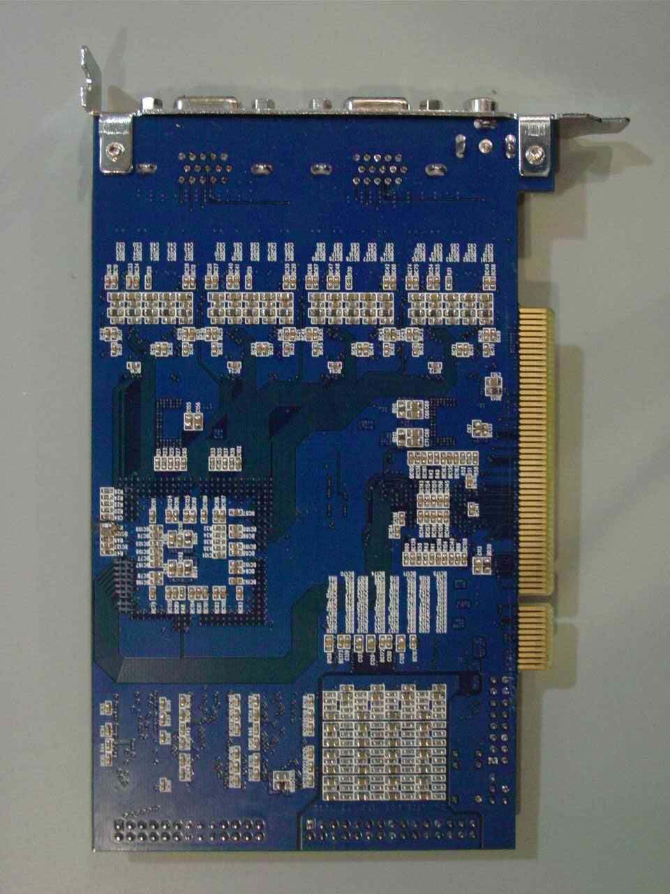
FCC ID.: QDZDF-5000 File No.: E03NR-013 ONETECH Testing & Evaluation Lab. FCC ID.: QDZDF-5000 File No.: E03NR-013 ONETECH Testing & Evaluation Lab. FCC ID.: QDZDF-5000 File No.: E03NR-013 ONETECH Testing & Evaluation Lab. FCC ID.: QDZDF-5000 File No.: E03NR-013 ONETECH Testing & Evaluation Lab.
Test Report
Page 1 of 13 FCC ID. : QDZDF-5000 File No. : E03NR-013 It should not reproduced except in full, written approval of ONETECH. EMC-004 (Rev.0) HEAD OFFICE : #505 SK APT. Factory 223-28, Sangdaewon 1 Dong, Jungwon-Gu, Seongnam-City, Kyunggi-Do, 462-121, Korea (TEL: +82-31-746-8500, FAX: 82-31-746-8700) EMC Testing Dept : 426-1 Daessangryung-Ri, Chowol-Myun, Kwangju-Si, Kyunggi-Do 464-860 Korea. (TEL: +82-31-765-8289, FAX: 82-31-766-2904) ONETECH Testing & Evaluation Lab. ELECTROMAGNETIC EMISSION C OMPLIANCE REPORT FOR FCC CLASS B CERTIFICATION Test report file number : E03NR-013 Applicant : SEDO CO., LTD. Address : 64-3 Sangdaewon-Dong, Jungwon-Gu, Sungnam-Si, Kyunggido Korea Manufacturer : SEDO CO., LTD. Address : 64-3 Sangdaewon-Dong, Jungwon-Gu, Sungnam-Si, Kyunggido Korea Type of Equipment : DVR CARD FCC ID : QDZDF-5000 Model / Type No. : DF-5000 Serial number : N/A Total page of Report : 16 pages (including this page) Date of Incoming : October 22, 2003 Date of issuing : November 5, 2003 SUMMARY The equipment complies with the regulation; FCC CFR 47 PART 15 SUBPART B, Class B. This test report contains only the result of a single test of the sample supplied for the examination. It is not a general valid assessment of the features of the respective products of the mass-production. Prepared by: Reviewed by: G. W. Lee / Chief Engineer Y. K. Kwon / Director EMC Dept. EMC Dept. ONETECH Corp. ONETECH Corp. Page 2 of 13 FCC ID. : QDZDF-5000 File No. : E03NR-013 It should not reproduced except in full, written approval of ONETECH. EMC-004 (Rev.0) HEAD OFFICE : #505 SK APT. Factory 223-28, Sangdaewon 1 Dong, Jungwon-Gu, Seongnam-City, Kyunggi-Do, 462-121, Korea (TEL: +82-31-746-8500, FAX: 82-31-746-8700) EMC Testing Dept : 426-1 Daessangryung-Ri, Chowol-Myun, Kwangju-Si, Kyunggi-Do 464-860 Korea. (TEL: +82-31-765-8289, FAX: 82-31-766-2904) ONETECH Testing & Evaluation Lab. CONTENTS Page 1. VERIFICATION OF COMPLIANCE ............................................................................................................................3 2. GENERAL INFORMATION...........................................................................................................................................4 2.1 PRODUCT DESCRIPTION................................................................................................................................................4 2.2 MODEL DIFFERENCE.....................................................................................................................................................4 2.3 RELATED SUBMITTAL(S) / GRANT(S)...........................................................................................................................4 2.4 TEST SYSTEM DETAILS.................................................................................................................................................5 2.5 TEST METHODOLOGY...................................................................................................................................................5 2.5 TEST FACILITY..............................................................................................................................................................5 3. SYSTEM TEST CONFIGURATION..............................................................................................................................6 3.1 JUSTIFICATION..............................................................................................................................................................6 3.2 EUT EXERCISE SOFTWARE...........................................................................................................................................6 3.3 CABLE DESCRIPTION....................................................................................................................................................6 3.4 NOISE SUPPRESSION PARTS ON CABLE........................................................................................................................7 3.5 EQUIPMENT MODIFICATIONS.......................................................................................................................................7 3.6 CONFIGURATION OF TEST SYSTEM..............................................................................................................................7 4. PRELIMINARY TEST .....................................................................................................................................................8 4.1 AC POWER LINE CONDUCTED EMISSION TEST...........................................................................................................8 4.2 RADIATED EMISSION TEST...........................................................................................................................................8 5. FINAL RESULT OF MEASURMENT ...........................................................................................................................9 5.1 CONDUCTED EMISSION TEST........................................................................................................................................9 5.2 RADIATED EMISSION TEST.........................................................................................................................................11 6. FIELD STRENGTH CALCULATION .........................................................................................................................12 7. LIST OF TEST EQUIPMENT.......................................................................................................................................13 Page 3 of 13 FCC ID. : QDZDF-5000 File No. : E03NR-013 It should not reproduced except in full, written approval of ONETECH. EMC-004 (Rev.0) HEAD OFFICE : #505 SK APT. Factory 223-28, Sangdaewon 1 Dong, Jungwon-Gu, Seongnam-City, Kyunggi-Do, 462-121, Korea (TEL: +82-31-746-8500, FAX: 82-31-746-8700) EMC Test…
Text truncated - open the document above for the full version.
Test Setup Photos
FCC ID. : QDZDF-5000 File No. : E03NR-013 ONETECH Testing & Evaluation Lab. FCC ID. : QDZDF-5000 File No. : E03NR-013 ONETECH Testing & Evaluation Lab.
Contact Information
Applicant
Nam S Jo(Manager)
[email protected]82-31-741-0303
Test Firm
ONETECH Corp.Gea-Won Lee
Technical Specifications
| # | Rule Parts | Frequency Range | Power Output |
|---|---|---|---|
| 1 | 15B | - | - |
Other Applications from SEDO Co., Ltd.
QDZDF9400
Nov 06, 200516 Channel Digital Video Recorder PCI Type (DVR)
Equipment Class
JBP - Part 15 Class B Computing Device Peripheral
QDZDF-7500
Feb 03, 2004DVR BOARD
Equipment Class
JBP - Part 15 Class B Computing Device Peripheral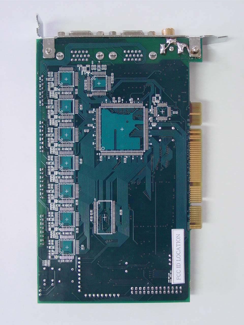
QDZDF-4900
Nov 24, 2003Digital Video Recorder ( DVR ) Card
Equipment Class
JBP - Part 15 Class B Computing Device Peripheral