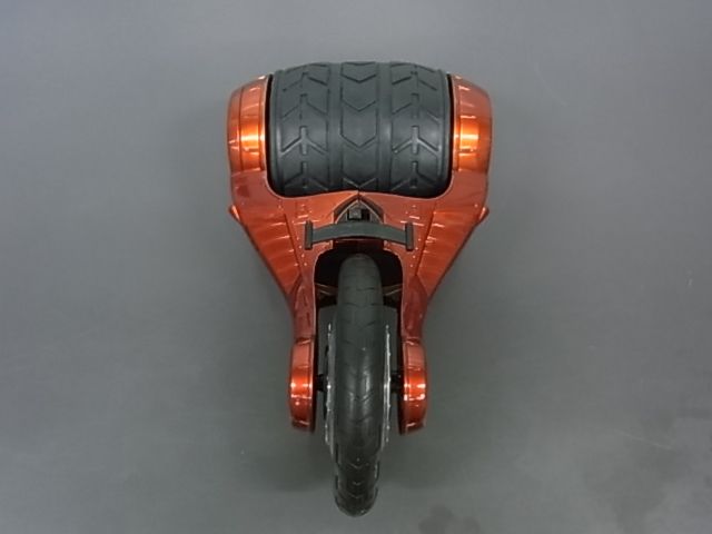
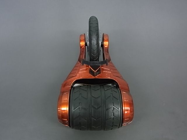
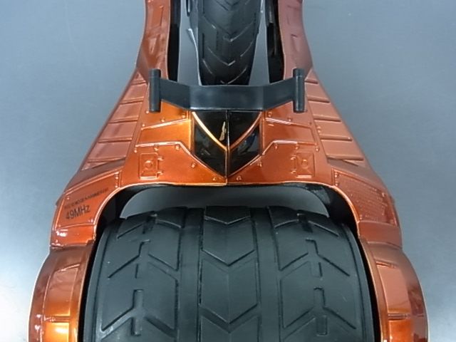
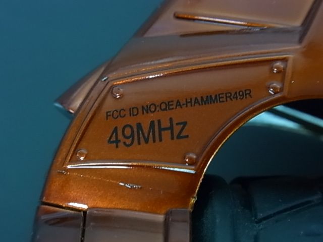
QEA-HAMMER49RHAMMERHEAD R/C
Kid Galaxy Inc.
Click to zoom
Application Details
- Equipment Class
- CRR - Superregenerative Receiver
- Date of Grant
- Jul 14, 2013
- Application Purpose
- Original Equipment
- Date of Application
- Jul 14, 2013
- Equipment Note
- HAMMERHEAD R/C
- Frequency Range
- 49.86000000 - 49.86000000
- Company
- Kid Galaxy Inc.
- Country
- United States
Documents & Files
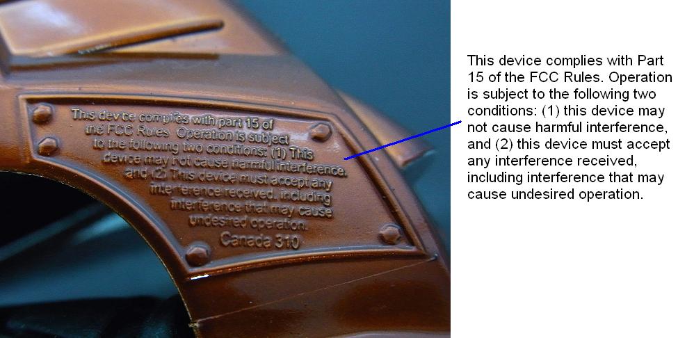
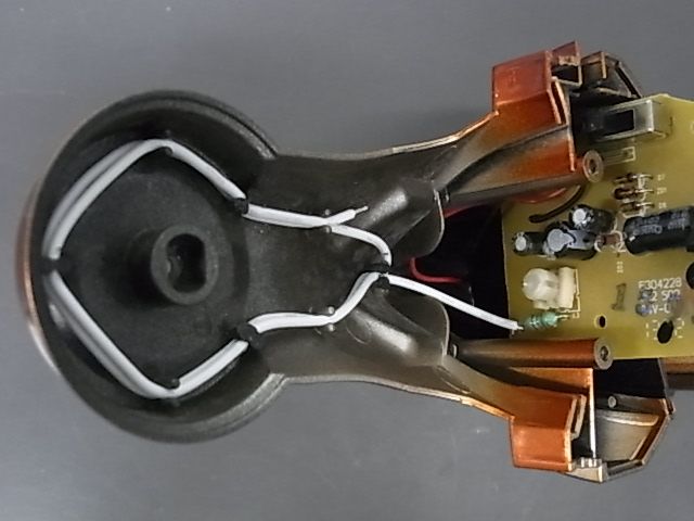
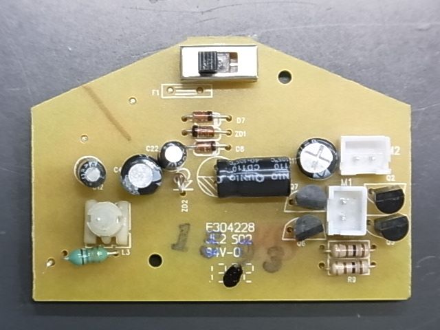
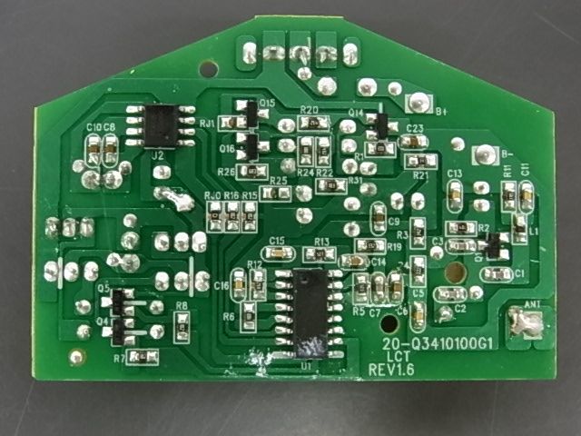
Document Text
Text extracted from the exhibit documents filed with the FCC. Open a document above to read the original.
Users Manual
BATTERY INSTALL/REPLACEMENT Instructions DRIVING YOUR HAMMERHEAD WARNING! + + + - - - Hammerhead is equipped with low battery auto shuto feature. Replace the batteries when Hammerhead shuts down." if not installed and used in accordance with the instructions, may cause harmful interference to radio communications. However, there is no guarantee that interference will not occur in a particular installation. If this equipment does cause harmful interference to radio or television reception, which can be determined by turning the equipment o and on.
Cover Letter(s)
KID GALAXY INC FCC ID: QEA-HAMMER49R POWER OF ATTORNEY 2013-6-20 Federal Communications Commission Authorization and Evaluation Division 7435 Oakland Mills Road Columbia, MD 21046 To Whom It May Concern: We, the undersigned, hereby authorize CMA Industrial Development Foundations Limited (Andrew Wong) on our behalf, to apply to the Federal Communications Commission on our equipment. Any and all acts carried out by CMA Industrial Development Foundation Limited (Andrew Wong) on our behalf shall have the same effect as acts of our own. This authorization expires one year from original date. This is to advise that we are in full compliance with the Anti-Drug Abuse Act. We, KID GALAXY INC, are not subject to a denial of federal benefits pursuant to Section 5301 of the Anti-Drug Act of 1988, 21 USC853a, and no party to the application is subject to a denial of federal benefits pursuant to that section. Sincerely, KID GALAXY INC
Operational Description
Data Sheet PT8A977P/977W/978P/978LW 5-Function Remote Controller PT0074(10/01) Ver:1 1 ||||||||||||||||||||||||||||||||||||||||||||||||||||||||||||||||||||||||||||||||||||||||||||||||||||||||||||||||||||||||||||||||||||||||||||||||||||||||||||||||||||||||||||||||||||||||||||||||||||||||||||||||||||||||||||||||||||||||||||||||||||||||||||||||||| Features • PT8A977P/977W works as encoder and PT8A978P/978LW works as decoder • Five pins for five control functions • Operating power-supply voltage: 2.5V to 5.0V (977P, 977W, 978P), 2.0V to 5.0V (978LW) • Auto-power-off if no press on any button in 8s or continuously press on any button over 4 minues • Press on any button as wake up (977P, 977W) • Manual-power-off with OFF button • One output pin used for external power control (977P, 977W) • On-chip oscillator with an external resistor • On-chip reversing amplifiers (978P, 978LW) • Low operating current • Few external components needed • Package: 14-pin DIP, 14-pin SOIC, 16-pin DIP and 16-pin SOIC General Description The PTA977P (or 977W) and PT8A978P (or 978LW) provide a complete control functions to the remote- controlled toy. The PT8A977P/977W has five input pins corresponding with the five function buttons i.e, forward, backward, rightward, leftward and turbo. The encoding circuit in the PT8A977P/977W sends digital codes to the two output pins SO and SC. The digital codes correspond to the definite function buttons or their combinations. The SO and SC outputs are used in wireless and infra-red applications respectively. The PT8A978P (or 978LW) has five output pins corresponding with the five actions. The received signals are amplified by the three-stage amplifier, and then the appropriate amplified signals are sampled, fault-tolerantly checked and decoded to control the actions of the remote-controlled toy. There is an internal oscillator in the PT8A977P/977W and 978P/978LW respectively. By adding an external resistor conveniently, the oscillator will be constructed. The oscillator frequency can be adjusted by the external resistor. The relative error between the frequencies of the two on-chip oscillators in the PT8A977P/977W and PT8A978P/978LW must be less than ±25%. The auto-power-off function is achieved by an internal counter. The PC output is used to control on/off state of the external power supply. Pressing OFF button can also shut down the power supply. Press on any function button will wake up the chip promptly. .oNtraP.oNtraP .oNtraP .oNtraP.oNtraPegakcaPegakcaP egakcaP egakcaPegakcaP P779A8TPPIDnip-41 W779A8TPCIOSnip-41 P879A8TPPIDnip-61 WL879A8TPCIOSnip-61 Ordering Information Data Sheet PT8A977P/977W/978P/978LW 5-Function Remote Controller PT0074(10/01) Ver:1 2 ||||||||||||||||||||||||||||||||||||||||||||||||||||||||||||||||||||||||||||||||||||||||||||||||||||||||||||||||||||||||||||||||||||||||||||||||||||||||||||||||||||||||||||||||||||||||||||||||||||||||||||||||||||||||||||||||||||||||||||||||||||||||||||||||||| Block Diagram of 978P/978LW OSCI OSCO Right Turbo Forward Backward Oscillator Timing Generator Decoding Circuit Latch Output Circuit Signal Sample & Fault-Tolerant Amp. Amp. Amp. SI VI1 VI2 VO1 VO2 Left LD RD Control Logic Check Pin Configuration Block Diagram Block Diagram of 977P/977W OSCI OSCO Right Left Turbo Forward Backward Oscillator Input Circuit Timing Generator Encoding Circuit 4 Minutes Counter Output Circuit PC SO SC OFF Top View VI2 Backward GND Forward Turbo 1 2 3 4 5 6 7 14 13 12 11 10 9 8 Right Left OSCI OSCO LD V CC 15 16 RD VO2 SI VO1 VI1 PT8A978P/978LW 16-Pin DIP/16-pin SOIC OFF Backward GND Forward Turbo Test SC 1 2 3 4 5 6 7 14 13 12 11 10 9 8 Right Left OSCI OSCO PC V CC SO PT8A977P/977W 14-Pin DIP/14-Pin SOIC Data Sheet PT8A977P/977W/978P/978LW 5-Function Remote Controller PT0074(10/01) Ver:1 3 ||||||||||||||||||||||||||||||||||||||||||||||||||||||||||||||||||||||||||||||||||||||||||||||||||||||||||||||||||||||||||||||||||||||||||||||||||||||||||||||||||||||||||||||||||||||||||||||||||||||||||||||||||||||||||||||||||||||||||||||||||||||||||||||||||| Pin Description of 978P/978LW Pin No. 1 2 5 6 4 7 8 3 9 10 11 12 13 14 Pin NameDescription 15 16 VI2 VO2 SI OSCI OSCO LD RD Right Left Backward Forward Turbo V cc VI1 VO1 GND Input pin for the amplifier 2 Output pin for the amplifier 2 Input pin of the encoding signal Oscillator input pin Oscillator output pin With Pull-up resistor, leftward function disabled if this pin connected to GND. With Pull-up resistor, rightward function disabled if this pin connected to GND. Rightward output pin Leftward output pin Backward output pin Forward output pin Turbo output pin Positive power supply Input pin for the amplifier 1 Output pin for the amplifier 1 Negative power supply Pin Description Pin Description of 977P/977W Pin No. 1 2 5 6 4 7 8 3 9 10 11 12 13 14 Pin Name OFF Backward GND Forward Test Turbo SC SO V cc PC OSCO OSCI Left Right Description With Pull-up resistor, this pin is used to shut down the external power supply. With Pull-up resistor, backward function selected if this pin connected to GND. Negative power supply With Pull-up resistor, forward function selected if this pin connected to GND. With Pull-up resistor, turbo function selected if this pin connected to GND. With Pull-up resistor, leftward function selected if this pin connected to GND. With Pull-up resistor, rightward function selected if this pin connected to GND. With Pull-up resistor, this pin is used for testing mode. Output pin of the encoding signal with carrier frequency Output pin of the encoding signal without carrier frequency Positive power supply Power control output pin Oscillator output pin Oscillator input pin Data Sheet PT8A977P/977W/978P/978LW 5-Function Remote Controller PT0074(10/01) Ver:1 4 |||||||||||||||||||||||||||||||||||||||||||||||||||||||||||||||||||||||||||||||||||||||||||||||||||||||||||||||||||||||||||||||||||||||||||||||||||||||||||||||||||||||||||||||||||||||||||||||||||||||||||||||||||||||||||||||||||…
Text truncated - open the document above for the full version.
Operational Description
Kid Galaxy Kid Galaxy Kid Galaxy Kid Galaxy Hammer Head RC Hammer Head RCHammer Head RC Hammer Head RC RX RXRX RX OPERATION PRINCIRLE OPERATION PRINCIRLEOPERATION PRINCIRLE OPERATION PRINCIRLE The Kid Galaxy Hammer Head RC operates at 49.860MHz,encode signals were received from antenna then passed into the super regeneration band pass filter circuit for wave-check;After Pre-amplification then passed into the decoder of the IC,the controlling signals corresponding to TX will be demodulated out to control the car’s functions of frontward;backward. turn left,turn right. Circuits CircuitsCircuits Circuits’ ’’ ’composition: composition:composition: composition: Power circuit,super regeneration band pass filter and amplifier circuit,pre-amplified circuit,decoder circuit,motor front/back circuit. 1.Power circuit: SW1,Q14.C23.R21.C4.C9.ZD2.R3 2.Low voltage protect circuit R1.C22.C21.D8.D7.R26.R22.Q15.Q16.R31.R24.ZD1.R20 3.super regeneration band pass filter and amplifier circuit: L1.L2.L3.C2.C1.Q1.C3.R2.C12.C13.R11.C11.R4 4.pre-amplified circuit: C5.C6.C7.R5.R19.C14.R13.R12.C15.C16. 4.decoder circuit: U1,R6 5. car front/back circuit: R7.R8.R9.R10.Q2.Q3.Q4.Q5.Q6.Q7 6. car right/left circuit: R15.R16.U2.C17.C8.C10.
Schematics
20-Q3410100G1.(49MHz)RX.sch-1 - Fri Jun 21 16:27:30 2013
Test Report
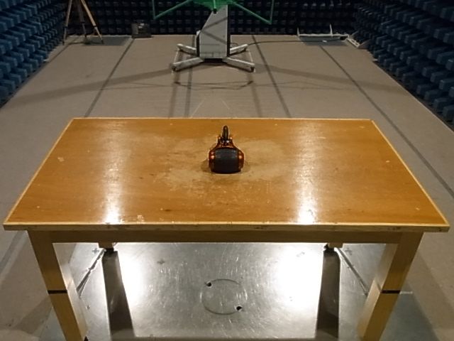
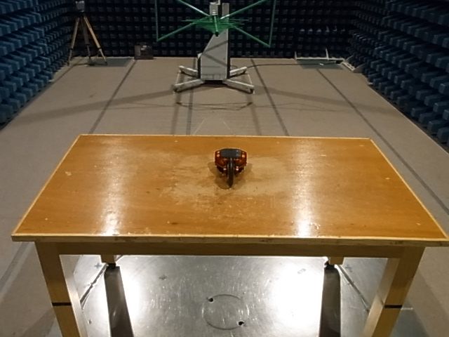
TEST REPORT Report No. : AR0033947(4) Date : 03 Ju1 2013 For and on behalf of CMA Industrial Development Foundation Limited Authorized Signature : Page 1 of 22 Mr. WONG Lap-pong, Andrew Assistant Manager Electrical Division FCC ID: QEA-HAMMER49R Application No. : LR015608(9) Client : Kid Galaxy Inc 150 Dow Street, Unit 425B Manchester, nh03101 Sample Description : One(1) item of submitted sample stated to be Hammer Head of Model No. 10190 Sample registration no. : RR021280-001 Radio Frequency : 49.860MHz Receiver Rating : 6 x 1.5V AA size batteries No. of submitted sample : Five (5) piece (s) Date Received : 20 May 2013 Test Period : 23 May 2013 to 18 Jun 2013 Test Requested : FCC Part 15 Certification. Test Method : 47 CFR Part 15 (10-1-10 Edition) ANSI C63.4 – 2009 Test Result : See attached sheet(s) from page 2 to 22. Conclusion : The submitted sample was found to comply with requirement of FCC Part 15 Subpart B. TEST REPORT Report No. : AR0033947(4) Date : 03 Ju1 2013 Page 2 of 22 FCC ID: QEA-HAMMER49R Table of Contents 1 General Information ................................................................................................................................... 3 1.1 General Description ............................................................................................................................ 3 1.2 Location of the test site ....................................................................................................................... 4 1.3 List of measuring equipment............................................................................................................... 5 1.4 Measurement Uncertainty ................................................................................................................... 5 2 Description of the radiated emission test ................................................................................................... 6 2.1 Test Procedure .................................................................................................................................... 6 2.2 Test Result .......................................................................................................................................... 6 2.3 Radiated Emission Measurement Data ............................................................................................... 7 3 Description of the Line-conducted Test ..................................................................................................... 8 3.1 Test Procedure .................................................................................................................................... 8 3.2 Test Result .......................................................................................................................................... 8 3.3 Graph and Table of Conducted Emission Measurement Data ............................................................ 8 4 Photograph ................................................................................................................................................. 9 4.1 Photographs of the Test Setup for Radiated Emission and Conducted Emission ............................... 9 4.2 Photographs of the External and Internal Configurations of the EUT................................................ 9 5 Supplementary document ......................................................................................................................... 10 5.1 Bandwidth ......................................................................................................................................... 10 5.2 Duty cycle ......................................................................................................................................... 10 5.3 Transmission time ............................................................................................................................. 10 6 Appendices...............................................................................................................................................11 TEST REPORT Report No. : AR0033947(4) Date : 03 Ju1 2013 Page 3 of 22 FCC ID: QEA-HAMMER49R 1 General Information 1.1 General Description The equipment under test (EUT) is a receiver for Hammer Head RC. It operates at 49.860MHz and the oscillation of radio control is generated by a LRC circuit. The EUT is powered by 6 x 1.5V AA size batteries. When it switched on and received radio control signal, it will take corresponding action. The brief circuit description is listed as follows: - SW1, Q14, C23, R21, C4, C9, ZD2 and its associated circuit act as power circuit. - R1, C22, C21, D8, D7, R26, R22, Q15, Q16, R31, R24, ZD1, R20 and its associated circuit act as low voltage protect circuit. - L1, L2, L3, C2, C1, Q1, C3, R2, C12, C13, R11, C11, R4 and its associated circuit act as super regeneration band pass filter and amplifier circuit. - C5, C6, C7, R5, R19, C14, R13, R12, C15, C16 and its associated circuit act as pre-amplified - U1, R6 and its associated circuit act as decoder circuit - R7, R8, R9, R10, Q2, Q3, Q4, Q5, Q6, Q7 and its associated circuit act as car front / back circuit - R15, R16, U2, C17, C8, C10 and its associated circuit act as car right / left circuit TEST REPORT Report No. : AR0033947(4) Date : 03 Ju1 2013 Page 4 of 22 FCC ID: QEA-HAMMER49R 1.2 Location of the test site FCC Registered Test Site Number: 552221 Radiated emissions measurements are investigated and taken pursuant to the procedures of ANSI C63.4 – 2009. A Semi-Anechoic Chamber Testing Site is set up for investigation and located at: Ground Floor, Yan Hing Centre, 9 – 13 Wong Chuk Yeung Street, Fo Tan, Shatin, New Territories, Hong Kong. Conducted emissions measurements are investigated and also taken pursuant to the procedures of ANSI C63.4 – 2009. A shielded room is located at : Ground Floor, Yan Hing Centre, 9 – 13 Wong Chuk Yeung Street, Fo Tan, Shatin, Ne…
Text truncated - open the document above for the full version.
Contact Information
Applicant
Irene Ngai(VP of Operations)
Test Firm
CMA Industrial Development Foundations LimitedAndrew Wong
Technical Specifications
| # | Rule Parts | Frequency Range | Power Output |
|---|---|---|---|
| 1 | 15B | 49.86 MHz - 49.86 MHz | - |
Other Applications from Kid Galaxy Inc.

QEA-10372-2G4T
Aug 18, 2026Turbo Strike RC Racer
Equipment Class
DXX - Part 15 Low Power Communication Device Transmitter
QEA-60245-2G4T
Apr 09, 2026RC CAR
Equipment Class
DXX - Part 15 Low Power Communication Device Transmitter
QEA-10356-49MT
Sep 03, 2024PZ MINI RC 2PK(49MHZ)
Equipment Class
DXX - Part 15 Low Power Communication Device Transmitter
QEA-10357-49MT
Apr 09, 2024Racer With Driver RC
Equipment Class
DXX - Part 15 Low Power Communication Device Transmitter
QEA-10353-49MT
Apr 03, 2024Body Light Up RC Racer
Equipment Class
DXX - Part 15 Low Power Communication Device Transmitter