QEUFODXFV2Foreign Object Debris Radar
Trex Aviation Systems Corporation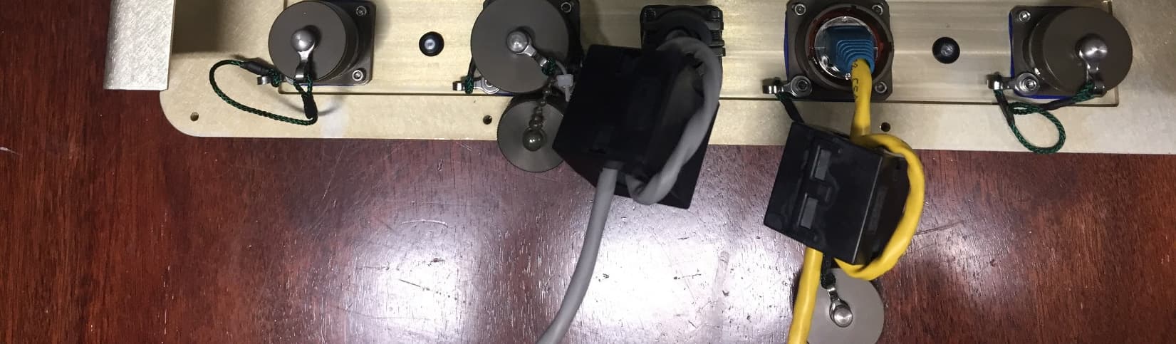
Click to zoom
Application Details
- Equipment Class
- VRD - Part 95 Vehicular Radar Systems
- Date of Grant
- Jan 10, 2021
- Application Purpose
- Original Equipment
- Date of Application
- Jan 10, 2021
- Equipment Note
- Foreign Object Debris Radar
- Frequency Range
- 78000.00000000 - 81000.00000000
- Country
- United States
Documents & Files
Document Text
Text extracted from the exhibit documents filed with the FCC. Open a document above to read the original.
Users Manual
FOD Finder™XFV2 RadarUsers Manual 12/08/2020 Table of Contents 2 1- Radar Configurations and Installation a) Fixed platform (tower) installationsb) Mobile platform (truck-mounted) installationsc) DC power connectiond) Data transfer connectione) Radar beam orientation f) FCC info and Caution to the user 2- Operating instructions a) Powering up the systemb) Run-time software instructionsc) Calibration and verification 3- RF Safety a) RF power informationb) Safe expose levels and distances 4- System Warranty and Troubleshooting Fixed Platform (Tower) Installation Radar mount assembly with azimuth/elevation pointin g adjustment, attached to a tower using U-bolt hardware 3 Radar mounted directly to fixed az/el positioner 4 Fixed Platform (Tower) Installation, cont. Mobile Platform Installation Radar is integrated with light bar, mounts to vehic ular roof rack 5 Radar DC Power and Data Connections • DC power provided through a 5-pin Amphenol connector P/N PT06A-14-3P(SR) • Radar powered by +24VDC at approximately 3A • Data transmitted through standard Cat-5 cable, interfaced with Amphenol connector and shield P/N RJFTV6MG • A clip-on one-turn inductor, Fair-Rite P/N 0443167251, is integrated with each cable to reduce the radiated emissions below FCC limit specifications 6 Radar Beam Orientation The radar beam is concentrated by a microstrip patc h-array antenna, onto a sector of 120 degrees in azimuth by 1 degree in elevation. This fan beam scans with RF frequency over 4 degrees of elevation during every chirp. The radar is mounted to align the area of surveillance with this window. 7 FCC info and Caution to the user This device complies with part 15 of the FCC Rules. Operation is subject to the following two conditions: (1) This d evice may not cause harmful interference, and (2) this device mus t accept any interference received, including interference that may cause undesired operation.Note that changes or modifications to the Radar uni t not expressly approved by Trex Aviation Systems could v oid the user’s authority to operate the equipment. 8 System Power-Up The FOD Finder XFV2 radar system power is delivered from a power box at the base of the tower, or on a service platform within 10m of the radar unit. The power box includes a circuit break er switch that controls AC power. AC power activates an AC-to-DC power supply that provides 24VDC to the unit.When the AC circuit breaker is turned on, the radar unit starts a 3- minute boot-up, initialization and calibration sequ ence. After this time interval the unit begins transmitting RF power and processing the radar returns. 9 Startup Instructions: Run-Time Software 10 Open the Program Folder “Static-CDMA” as shown to the right Startup Instructions: Run-Time Software (cont.) Double-click on the “Processing” tab as shown to the right 11 Startup Instructions: Run-Time Software (cont.) Open the “CDMA_MultiRadar” script: 12 Startup Instructions: Run-Time Software (cont.) The radar begins transmitting, and return data are displayed in a blue box of varying color, indicating magnitude of signal.Slider bars above the return image can be adjusted via the computer mouse, to alter the display or select system operating parameters. 13 FOD Finder Radar Calibration and Verification 14 The FOD Finder XF radar requires an initial calibra tion to operate at optimum performance. The calibration procedure measures th e relative response, in phase and amplitude, of all transmit and receive channel combinations in use by the radar. This calibration data is collected by acquiring rad ar data from a single, strong return source placed in the radar far-field, such as a cor ner cube, and is measured at twelve different frequencies across the radar band. The c alibration data is then stored on the internal radar processor and applied to all rad ar signals during operation to produce a high-gain beam shape. Importantly, this calibration is applied at the data processing level and does not require any adjustmen t of the radar system hardware. Data for a new calibration can be generated by obse rving radar returns from a known target and a new calibration can be applied s imply by re-writing the calibration file on the radar.The FOD Finder radar is fully calibrated at the fac tory and then an additional calibration is performed on site at the time of ins tallation. Calibration is verified by measuring the return signal from a radar target wit h a known radar cross-section. The system continues to automatically update its ph ase calibration during its operation based on the data returns from fixed obje cts within the radar field-of- view, comparing the returns from those objects at t he time of installation to the returns from those objects at the present time. No input is required by the operator for the calibration update to occur. FOD Finder Radar Calibration and Verification (cont .) The radar calibration is a function of the relative electrical line lengths of traces within the radar and the impedance of the radar MMW circuits. If no physical changes are made to the radar, these values do not change appreciably. There may be small changes in the system parameters over time due to changes in temperature or aging of components. Automatic upda tes to the calibration files, based on the returns of known objects in the field- of-view (such as runway landing lights), are incorporated to correct for th ese small changes over time. Calibration of the radar is verified by monitoring returns from fixed objects within the radar field-of-view and comparing the cu rrent phase and amplitude of returns to those measured when the radar was first installed. This requires no user action, assuming said data is exportable to Tr ex Aviation for analysis. As part of a standard system performance verification, current radar returns and calibration data are exported to Trex Aviation and the validity of the updated calibration file is confirmed. A visual image of a runway with side marking…
Text truncated - open the document above for the full version.
External Photos
Radar External Photo’s Radar Front View 2 Radar Side View 3 Radar back Top View 4 Radar Back side lower 5
ID Label/Location Info
Label information as show below and in the photo below. Model Number: FODXFV2 Serial No: 003 Manufacture: Trex Aviation Systems Corporation (FCC ID: QEUFODXFV2) Part Number 100-1101-001 Label Location shown below on the lower backside of the unit Label size is .75 inch High by 4 inches long The material we use is and Avery 5523 Laser labels. These are Weatherproof, White labels that are self adhesive and durable construction that is guaranteed to stand up to extremes of weather and temperature. We have been using this product successfully for over five years without any noticeable degradation of unit in the field so expect the labels to easy withstand the 10 year life of the radar system. Part 15 info is located on the other side as show below.
RF Exposure Info
Intertek Report Number: 104421478BOX-001 Issued: 10/15/2020 Revised: 12/22/2020 Non-Specific Radio Report Shell Rev. December 2017 Page 16 of 46 Trex Enterprises Corporation, Model: FODXFV2 Client specified safe distance of 3 m or 300 cm. Intertek Report Number: 104421478BOX-001 Issued: 10/15/2020 Revised: 12/22/2020 Non-Specific Radio Report Shell Rev. December 2017 Page 17 of 46 Trex Enterprises Corporation, Model: FODXFV2 1.2 Results: • EIRP = 37.51 dBm or 5.636W=5626mW Power Density = 5626 / 1130500 Power Density = 0.004977 mW/cm 2 Limit at 80.6496GHz = 1mW/cm 2 The calculated maximum power density at 3m distance is less than the limit for general population / uncontrolled exposure. Test Personnel: Vathana Ven Test Date: 09/17/2020 Supervising/Reviewing Engineer: (Where Applicable) N/A Product Standard: CFR47 FCC Part 95, Subpart M Limit Applied: See report section 6.3 Input Voltage: 120VAC 60Hz Pretest Verification w/ Ambient Signals or BB Source: N/A Ambient Temperature: 21 ºC Relative Humidity: 46 % Atmospheric Pressure: 1007 mbars Deviations, Additions, or Exclusions: None
Test Report
TREX ENTERPRISES CORPORATION TEST REPORT SCOPE OF WORK EMISSIONS TESTING – MODEL FODXFV2 REPORT NUMBER 104421478BOX-001 ISSUE DATE REVISED DATE 15-October-2020 22-December-20 20 PAGES 46 DOCUMENT CONTROL NUMBER Non-Specific Radio Report Shell Rev. December 2017 © 2017 INTERTEK Non-Specific Radio Report Shell Rev. December 2017 Page 2 of 46 Trex Enterprises Corporation, Model: FOD Finder™ XFV2 EMISSIONS TEST REPORT (FULL COMPLIANCE) Report Number: 104421478BOX-001 Project Number: G104421478 Report Issue Date: 10/15/2020 Report Revision Date: 12/22/2020 Model(s) Tested: FODXFV2 Model(s) Partially Tested: None Model(s) Not Tested but declared equivalent by the client: None Standards: FCC 47CFR Part 95, Subpart M:10/2020 KDB447498 D01 General RF Exposure Guidance v06 Tested by: Client: Intertek Testing Services NA, Inc. 70 Codman Hill Road Boxborough, MA 01719 USA Trex Enterprises Corporation 10455 Pacific Center Court San Diego, CA 92121-4339 USA Report prepared by Report reviewed by Vathana Ven/EMC Staff Engineer Michael F Murphy / EMC Engineering Team Lead This report is for the exclusive use of Intertek's Client and is provided pursuant to the agreement between Intertek and its Client. Intertek's responsibility and liability are limited to the terms and conditions of the agreement. Intertek assumes no liability to any party, other than to the Client in accordance with the agreement, for any loss, expense or damage occasioned by the use of this report. Only the Client is authorized to permit copying or distribution of this report and then only in its entirety. Any use of the Intertek name or one of its marks for the sale or advertisement of the tested material, product or service must first be approved in writing by Intertek. The observations and test results in this report are relevant only to the sample tested. This report by itself does not imply that the material, product, or service is or has ever been under an Intertek certification program. Intertek Report Number: 104421478BOX-001 Issued: 10/15/2020 Revised: 12/22/2020 Non-Specific Radio Report Shell Rev. December 2017 Page 3 of 46 Trex Enterprises Corporation, Model: FODXFV2 Table of Contents 1 Introduction and Conclusion .............................................................................................................. 4 2 Test Summary ...................................................................................................................................... 4 3 Client Information ................................................................................................................................ 5 4 Description of Equipment Under Test and Variant Models ............................................................. 5 5 System Setup and Method .................................................................................................................. 6 6 Maximum Power and Human RF exposure ....................................................................................... 8 7 Occupied Bandwidth ......................................................................................................................... 18 8 Unwanted Emissions ......................................................................................................................... 23 9 Frequency Stability ............................................................................................................................ 38 10 Appendix A – Mixer/Horn Calibration Certificates ...................................................................... 41 11 Revision History ............................................................................................................................. 46 Intertek Report Number: 104421478BOX-001 Issued: 10/15/2020 Revised: 12/22/2020 Non-Specific Radio Report Shell Rev. December 2017 Page 4 of 46 Trex Enterprises Corporation, Model: FODXFV2 1 Introduction and Conclusion The tests indicated in section 2.0 were performed on the product constructed as described in section 4.0. The remaining test sections are the verbatim text from the actual data sheets used during the investigation. These test sections include the test name, the specified test Method, a list of the actual Test Equipment Used, documentation Photos, Results and raw Data. No additions, deviations, or exclusions have been made from the standard(s) unless specifically noted. Based on the results of our investigation, we have concluded the product tested complies with the requirements of the standard(s) indicated. The results obtained in this test report pertain only to the item(s) tested. Intertek does not make any claims of compliance for samples or variants which were not tested. 2 Test Summary Section Test full name Result 3 Client Information -- 4 Description of Equipment Under Test and Variant Models -- 5 System Setup and Method --- 6 Maximum Power and Human RF exposure FCC 47CFR Part 95, Subpart M:10/2020, KDB447498 D01 General RF Exposure Guidance v06 Pass 7 Occupied Bandwidth FCC 47CFR Part 95, Subpart M:10/2020 Pass 8 Unwanted Emissions FCC 47CFR Part 95, Subpart M:10/2020 Pass 9 Frequency Stability FCC 47CFR Part 95, Subpart M:10/2020 Pass 10 Appendix A – Mixer/Horn Calibration Certificates -- 11 Revision History -- Intertek Report Number: 104421478BOX-001 Issued: 10/15/2020 Revised: 12/22/2020 Non-Specific Radio Report Shell Rev. December 2017 Page 5 of 46 Trex Enterprises Corporation, Model: FODXFV2 3 Client Information This EUT was tested at the request of: Client: Trex Enterprises Corporation 10455 Pacific Center Court San Diego, CA 92121-4339 USA Contact: Rich Chedester Telephone: 858-646-5300 Email: [email protected] 4 Description of Equipment Under Test and Variant Models Manufacturer: Trex Enterprises Corporation 10455 Pacific Center Court San Diego, CA 92121-4339 USA Equipment Under Test Description Manufacturer Model Number Serial Number FOD Finder XFV2 rada Trex Enterprises …
Text truncated - open the document above for the full version.
Test Setup Photos
Intertek Report Number: 104421478BOX-001 Issued: 10/15/2020 Non-Specific Radio Report Shell Rev. December 2017 Page 29 of 49 Trex Enterprises Corporation, Model: FODXFV2 8.4 Setup Photograph: 9kHz-30MHz Intertek Report Number: 104421478BOX-001 Issued: 10/15/2020 Non-Specific Radio Report Shell Rev. December 2017 Page 30 of 49 Trex Enterprises Corporation, Model: FODXFV2 30-1000MHz Intertek Report Number: 104421478BOX-001 Issued: 10/15/2020 Non-Specific Radio Report Shell Rev. December 2017 Page 31 of 49 Trex Enterprises Corporation, Model: FODXFV2 1-18 GHz Intertek Report Number: 104421478BOX-001 Issued: 10/15/2020 Non-Specific Radio Report Shell Rev. December 2017 Page 32 of 49 Trex Enterprises Corporation, Model: FODXFV2 18-40 GHz Intertek Report Number: 104421478BOX-001 Issued: 10/15/2020 Non-Specific Radio Report Shell Rev. December 2017 Page 33 of 49 Trex Enterprises Corporation, Model: FODXFV2 Above 40GHz
Contact Information
Applicant
Richard Chedester(Engineering Manager)
Technical Contact
Trex EnterprisesRichard Chedester
[email protected]4132210526
181 State Road · Whately · United States
Non-Technical Contact
Trex EnterprisesAllen Wolski
[email protected]8586465505
Test Firm
Intertek Testing Services NA Inc.Yaqing Liu
[email protected]978 635 8662
Technical Specifications
| # | Rule Parts | Frequency Range | Power Output | Emission |
|---|---|---|---|---|
| 1 | 95M | 78.00 GHz - 81.00 GHz | 5.636 W | 2G96F7D |
Other Applications from Trex Aviation Systems Corporation
QEUFODDRA1
Oct 03, 2012Foreign Object Debris Radar
Equipment Class
TNB - Licensed Non-Broadcast Station Transmitter