QFDCLPBMT1Room Monitor
ComLink Products, L.L.C.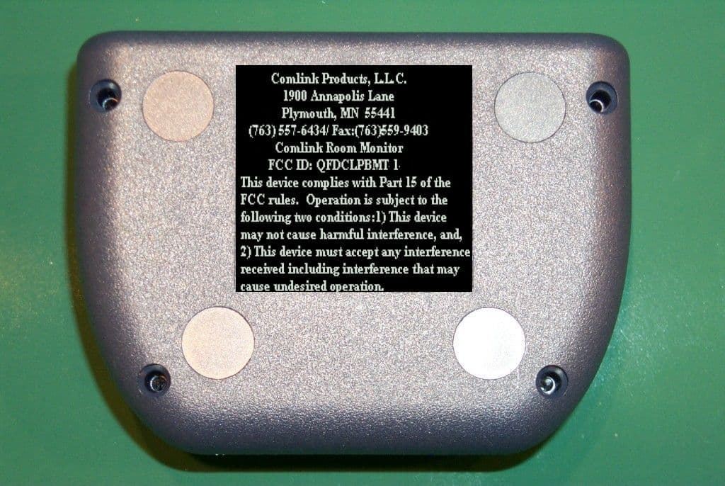
Click to zoom
Application Details
- Equipment Class
- DXX - Part 15 Low Power Communication Device Transmitter
- Date of Grant
- Sep 26, 2006
- Application Purpose
- Original Equipment
- Date of Application
- Sep 25, 2006
- Equipment Note
- Room Monitor
- Frequency Range
- 49.83000000 - 49.89000000
- Company
- ComLink Products, L.L.C.
- Country
- United States
Documents & Files
Document Text
Text extracted from the exhibit documents filed with the FCC. Open a document above to read the original.
Users Manual
***DRAFT*** Comlink Products, L.L.C. 1900 Annapolis Lane Plymouth, MN 55441 (763) 557-6434 / Fax (763) 559-9403 Comlink Room Monitor FCC ID: QFDCLPBMT1 and QFDCLPBMT2 This device complies with Part 15 of the FCC rules. Operation is subject to the following two conditions:1) This device may not cause harmful interference, and, 2) This device must accept any interference received including interference that may cause undesired operation. Important Cautions! O Changes or modifications not expressly approved by Comlink Products, L.L.C. could void the user’s authority to operate the equipment. O The Comlink Room Monitor is not intended to replace responsible adult supervision nor is it intended to be used as a medical monitor. O The adapter cord should be kept out of the reach of children; do not use this product with extension cords; use only with 110-120 Volt AC electrical outlets. O DO NOT place the Comlink Transmitter or its adapter cord within reach of your child or inside a crib or play area. O DO NOT place the adapter cord where it could be walked on or pinched by furniture or other items. O DO NOT immerse any part of the Comlink Room Monitor in water or place the device near possible wet locations such as bathtub, shower, sink, swimming pool, etc. O DO NOT place the Comlink Transmitter in a drawer or in any location(place) that might interfere with sound pickup or normal ventilation – also DO NOT locate the Transmitter near any sources of heat such as radiators or appliances. O DO NOT open the Comlink Room Monitor as there are no user serviceable parts inside – avoid the risk of electrical shock, fire or death. PAGE 2 COMLINK EARPIECE The Comlink Room Monitor Earpiece may be worn on either ear. Snap the Nylon EarHook (Figure 2) on to the Center post of the Earpiece as shown for the left ear (Figure 1) or the right ear (Figure 3). Feel free to bend and shape the Earhook for the best fit to your ear. FIGURE 1 FIGURE 2 FIGURE 3 Battery Types: Two (2) ‘button’ or ‘watch’ type batteries are included for your Comlink EarPiece. Type 357 (Silver Oxide) or Type 675 (Zinc-Air) batteries are recommended; and are widely available wherever batteries are sold. Batteries may also be ordered at competitive prices from ComLink Products, L.L.C. Battery Life: Type 357 Silver Oxide batteries provide approximately 1100 minutes (18 hours) of service with multi-month shelf life. Type 675 Zinc-Air batteries provide approximately 3600 minutes (60 hours)of service but typically do not have a shelf-life longer than 30 days after the activation tab is removed. Battery Installation: --Pry the battery tray out of Earpiece (Figure 4). --Note correct battery polarity from drawing inside battery tray (Figure 5) ; - ---Install the batteries as shown. (Figure 6) --Insert the battery tray into the Comlink Earpiece (Figure 7) Battery Tips: --Never recharge a non-rechargeable battery! --Only adults should change the batteries! --Never put a battery in the mouth! --Remove dead batteries promptly to avoid damage to the Earpiece Earpiece Operation The Volume Control wheel adjusts the sound level; rotate clockwise to make louder. “On” Button “Off” Button *Note: The Earpiece will automatically turn off after approximately 30 seconds if it is out of range from the transmitter or if the transmitter is unplugged. Hint: If you turn on the receiver power before transmitter power, you will hear a static noise. Simply turn the transmitter power on. Transmitter Operation Place the Transmitter in the room to be monitored and point the microphone toward the sound source. Unwrap and fully extend the AC adaptor cord. Insert the power plug into the power jack on the back panel of the Transmitter (Figure 8). The power indicator light should turn on. Note: As with all radio frequency devices, transmission range and reception may vary. Your Nursery Monitor uses public airwaves, so it is possible for conversation near the Room Monitor Transmitter to be broadcast to other room monitors, radios, cordless phones or scanners outside your home. For your privacy, always unplug the Room Monitor when not is use. This monitor operates on one or more of the following frequencies: A: 49.830 MHz,; B: 49.485MHz,; C: 49.860 MHz; D: 49.875MHz; E: 49.890 MHz ONE (1) YEAR LIMITED WARRANTY ComLink Products, L.L.C. , 1900 Annapolis Lane, Plymouth, MN 55441, warrants the ComLink Room Monitor is free from all defects in material and workmanship when used under normal condition for a period of one (1) year from the date of purchase. Should the product fail to perform properly, we will repair or replace it at our option, free of charge. Purchaser is responsible for shipping the product to Consumer Affairs at the address indicated above and for all associated freight and insurance costs. ComLink Products, L.L.C. will bear the cost of shipping the repaired or replaced item to you. This warranty is void if the owner repairs or modifies the product. This warranty excludes any liability other that that expressly stated above including but not limited to any incidental or consequential damages. SOME STATES DO NOT ALLOW THE EXCLUSION OR LIMITATION OF INCIDENTAL OR FOR CONSEQUENTIAL DAMAGES, SO THE ABOVE LIMITATION OR EXCLUSION MAY NOT APPLY TO YOU. THIS WARRANTY GIVES YOU SPECIFIC LEGAL RIGHTS, AND YOU MAY ALSO HAVE OTHER RIGHTS WHICH MAY VARY FROM STATE TO TSTATE. The electronic components in transmitter receiver and AC adaptor are not designed for consumer repair. Evidence of any attempt of consumer repair will void this warranty PROBLEM SOLVING If you hear no sound from your ComLink Earpiece 1) Did you activate the Earpiece by pushing its button? 2) Are the batteries in good condition? 3) Are the batteries correctly inserted into the Battery Trays? - - See Figure ( ). 4) Are the Battery Trays fully inserted into the Adaptor and EarPiece? FCC NOTE (United States Only) Note: This equipment has been tested and found to comply with the limits for a Class B digital device, p…
Text truncated - open the document above for the full version.
Attestation Statements
TÜV America Inc. Phone: (651) 638-0297 19333 Wild Mountain Road Fax: (651) 638-0298 Taylor Falls, MN 55084 E-mail: [email protected] www.TUVamerica.com Management Service • Product Service • Industry Service • Automotive • BABT TÜV America Inc. is a subsidiary of TÜV SÜD Group. TÜV AMERICA INC 19333 WILD MOUNTAIN ROAD TAYLORS FALLS, MINNESOTA 55084-1786 ENGINEERING STATEMENT For Certification of Comlink Products LLC Comlink Room Monitor with integral antenna and Comlink Room Monitor with external antenna Model No: CLP-BMT1 and CLP-BMT2 FCC ID: QFDCLPBMT1 FRN: 0007180466 I am an Electromagnetic Compatibility Engineer for TÜV AMERICA INC, Taylors Falls, Minnesota. My education and experience are a matter of record with the Federal Communications Commission. TÜV AMERICA INC has been authorized by Barry Voroba, CEO, of Comlink Products LLC, to make Certification measurements of the above mentioned equipment. I attest that all testing done under my supervision was done in accordance with, and that the EUT fulfills the requirements of, the Federal Communications Commission's CFR 47 Part 15.235 and Part 15.207. Joel T. Schneider Senior Engineer Minnesota Wild River Lab TÜV America Product Service Tel: 651 604 4582 Fax: 651 638 0298 [email protected] Dated: 15 September 2006
Block Diagram
Comlink Room Monitor Model CLP-BMT1 Comlink Room Monitor Model CLP-BMT2
External Photos
Room Monitor Model CLP-BMT1 Top & Front Room Monitor Model CLP-BMT1 Top & Back Room Monitor Model CLP-BMT2 Top & Front Room Monitor Model CLP-BMT2 Top & Back Room Monitor Model CLP-BMT1 & CLP-BMT2 Bottom
ID Label/Location Info
Comlink Room Monitor Label Sample and Placement
Internal Photos
Room Monitor Model CLP-BMT1 Cover Open Room Monitor Model CLP-BMT1 – Board Removed from Monitor Room Monitor Model CLP-BMT1 Top Board Room Monitor Model CLP-BMT1 Bottom Board Room Monitor Model CLP-BMT2 Cover Open Room Monitor Model CLP-BMT2 Top Board Room Monitor Model CLP-BMT2 Bottom Board
RF Exposure Info
TÜV America Inc. Phone: (651) 638-0297 19333 Wild Mountain Road Fax: (651) 638-0298 Taylor Falls, MN 55084 E-mail: [email protected] www.TUVamerica.com Management Service • Product Service • Industry Service • Automotive • BABT TÜV America Inc. is a subsidiary of TÜV SÜD Group. September 15, 2006 AmericanTCB 6731 Whittier Avenue McLean VA 22101 Attn: Director of Certification RE: Declaration of Compliance to RF Exposure Limits for Humans The Comlink CLPBMT1 and CLPBMT2 Room Monitors comply with the RF exposure limits for humans as called out in FCC section 2.1091 (mobile >20 cm) or 2.1093 (portable <20 cm), or RSS 102. The only difference between the two units is one has an external antenna, while the other has an integral antenna. The value of R10 for the CLPBMT1 is 62 ohms. The value of R10 for the CLPBMT2 is 75 ohms. The Comlink Room Monitor may be used in a residential dwelling for such purposes as a baby monitor. It is exempt from RF Evaluation based on its operating frequency of 49.860 MHz, and output power of 17 microwatts based on ERP (dBk) = E (dBuV/m) – 106.92 + 20 log D (km) = 79.78 – 106.92 + 20 log .003 = -77.5 dBk = 17 microwatts. This would be less than the 1.5 watts requirement for a mobile device, or the 200 milliwatts requirement for a portable device, operating at 49.860 MHz. Joel T. Schneider Senior Engineer Minnesota Wild River Lab TÜV America Product Service Tel: 651 604 4582 Fax: 651 638 0298 [email protected]
Test Report
TÜV AMERICA INC 19333 Wild Mountain Road Taylors Falls MN 55084 Tel: (651) 638-0297 Fax: (651) 638-0298Rev. 091306 TEST RESULT SUMMARY FCC Part 15 Subpart C Section 15.235 FCC Part 15 Subpart C Section 15.207 Industry Canada RSS-310 Issue 1 Industry Canada RSS-Gen Issue 1 MANUFACTURER'S NAME Comlink Products, L.L.C. NAME OF EQUIPMENT Comlink Room Monitor with integral antenna Comlink Room Monitor with external antenna MODEL NUMBER(S) TESTED CLP-BMT1 CLP-BMT2 MANUFACTURER'S ADDRESS 1900 Annapolis Ln Plymouth MN 55441 TEST REPORT NUMBER WC605021 TEST DATE(S) 4 Aug, 15 Aug, & 7 Sep, 2006 According to testing performed at TÜV America Inc, the above-mentioned unit is in compliance with the applicable electromagnetic compatibility (EMC) portions of the requirements defined in FCC Part 15 Subpart C Sections 15.235 and 15.207 and IC RSS-310 Issue 1 and RSS-Gen Issue 1. It is the manufacturer's responsibility to assure that additional production units of this model are manufactured with identical electrical and mechanical characteristics. Any modifications necessary for compliance made during testing on the above mentioned date(s) must be implemented in all production units for compliance to be maintained. TÜV America Inc, as an independent testing laboratory, declares that the equipment tested as specified above conforms to the applicable EMC requirements of FCC Part 15 Subpart C “Intentional radiators” Sections 15.235 “Operation within the band 49.82–49.90 MHz.” and 15.207 “Conducted limits” and IC RSS-310 Issue 1 “Low-power Licence-exempt Radiocommunication Devices (All Frequency Bands): Category II Equipment” and RSS-Gen “General Requirements and Information for the Certification of Radiocommunication Equipment” Date: 13 September 2006 Location: Taylors Falls MN Ross Johnson & Joe Sausen Joel Schneider USA EMC Technicians Senior EMC Engineer Not Transferable TÜV AMERICA INC 19333 Wild Mountain Road Taylors Falls MN 55084 Tel: (651) 638-0297 Fax: (651) 638-0298Rev. 091306 EMC TEST REPORT Test Report File No. : WC605021 Date of issue: 13 September 2006 Model / Serial No(s) Tested : CLP-BMT1 / --- CLP-BMT2 / --- Product Type : Room monitor with integral antenna Room monitor with external antenna Applicant : Comlink Products, L.L.C. Manufacturer : Comlink Products, L.L.C. License holder : Comlink Products, L.L.C. Address : 1900 Annapolis Ln Plymouth MN 55441 Test Result : Positive Negative Test Project Number References : WC605021 Total pages including Appendices : 39 TÜV America Inc reports apply only to the specific samples tested under stated test conditions. It is the manufacturer's responsibility to assure that additional production units of this model are manufactured with identical electrical and mechanical components. TÜV America Inc shall have no liability for any deductions, inferences or generalizations drawn by the client or others from TÜV America Inc issued reports. This report is the confidential property of the client. As a mutual protection to our clients, the public and ourselves, extracts from the test report shall not be reproduced except in full without our written approval. This report shall not be used by the client to claim product endorsement by NVLAP, NIST, or any agency of the US government. TÜV America Inc and its professional staff hold government and professional organization certifications and are members of AAMI, ACIL, AEA, ANSI, IEEE, NARTE, and VCCI. File no. WC605021Page 1 of 39 TÜV AMERICA INC 19333 Wild Mountain Road Taylors Falls MN 55084 Tel: (651) 638-0297 Fax: (651) 638-0298Rev. 091306 D I R E C T O R Y Documentation Page(s) Directory 2 Test Regulations, Environmental conditions, Power supply 3 Test Data and Results: FCC IC Field strength within band 15.235(a) RSS-310 3.8 4 - 6 Band edges, 49.81 - 49.82 MHz and 49.90 - 49.91 MHz 15.235(b) RSS-310 3.8 7 - 9 Emissions > 10 kHz from band edges 15.235(b) RSS-310 3.8 10 Occupied Bandwidth RSS-Gen 4.4.1 11 - 13 Conducted limits - AC Power lines 15.207(a) RSS Gen 7.2.2 14 - 19 Test area diagrams 20 - 21 Test setup photo(s) 22 - 26 Test Operation Mode, Configuration of the device under test 27 Deviations From Standard, General Remarks, Summary 28 Appendix A Constructional Data Form and Block Diagram 29 - 37 Appendix B Measurement Protocol 38 - 39 Sign Explanations: - not applicable - applicable File no. WC605021Page 2 of 39 TÜV AMERICA INC 19333 Wild Mountain Road Taylors Falls MN 55084 Tel: (651) 638-0297 Fax: (651) 638-0298Rev. 091306 EMC TEST REGULATIONS: The tests were performed according to the following regulations : - EN 55014-2: 1997 + Amendment A1: 2001 - Category __ - EN 55024: 1998 + Amendments A1: 2001 + A2: 2003 - EN 60601-1-2: 2001 - EN 61000-6-1: 2001 - EN 61000-6-2: 2001 - EN 61326: 1997 + Amendments A1: 1998 + A2: 2001 + A3: 2003 - EN 61800-3: 1996 + Amendment A11: 2000 - ETS 300 683: 1997 - ETSI EN 301 489-3 V1.4.1: 2002 - EN 300 330-2 V1.1.1 (2001-06) - FCC Part 15 Subpart C Section 15.235 - FCC Part 15 Subpart C Section 15.207 - IC RSS-310 Issue 1 - IC RSS-Gen Issue 1 - IC RSS-Gen Issue 1 ENVIRONMENTAL CONDITIONS IN THE LAB Actual Temperature : 20 - 24 °C Atmospheric pressure : 98 kPa Relative Humidity : 40 - 45 % POWER SUPPLY UTILIZED Power supply system : 110V, 60Hz File no. WC605021Page 3 of 39 TÜV AMERICA INC 19333 Wild Mountain Road Taylors Falls MN 55084 Tel: (651) 638-0297 Fax: (651) 638-0298Rev. 091306 Field strength within band FCC 15.235(a), IC RSS-310 3.8 Test summary The requirements are: - MET - NOT MET Minimum margin of compliance = 0.22 dB at 49.859 MHz Peak measurements are within 20 dB of average measurements Test location - Wild River Lab Large Test Site (Open Area Test Site) - Wild River Lab Small Test Site (Open Area Test Site) Test Distance - 3 meters - 10 meters Test equipment TUV ID Model Number Manufacturer Description Serial Number Cal Due 3995 EM-6917B Electro-Metrics Biconicalog Periodic 151 31-Mar-07 2665 ZHL-1042J Mi…
Text truncated - open the document above for the full version.
Test Setup Photos
TÜV AMERICA INC 19333 Wild Mountain Road Taylors Falls MN 55084 Tel: (651) 638-0297 Fax: (651) 638-0298Rev. 091306 TEST SETUP FOR EMISSIONS TESTING WILD RIVER LAB Large Test Site Notes: 1. Items shown in dotted lines are located on the floor below the test area. It is 5 meters vertically from the ground floor to the test area. 2. 50 Hz, 60 Hz, and 400 Hz are power panels for alternating current. 3. The antenna may be positioned horizontally 3, 10 or 30 meters from the center of the turntable. 4. The circle is a 6.7 meter diameter turntable. 5. A ground plane is in the plane of this sheet. 6. The test sample is shown in the azimuthal position representing zero degrees. EUT 0 90270 180 60 Hz 50 Hz 400 Hz Shielded Enclosure ANTENNA File no. WC605021Page 20 of 39 TÜV AMERICA INC 19333 Wild Mountain Road Taylors Falls MN 55084 Tel: (651) 638-0297 Fax: (651) 638-0298Rev. 091306 TEST SETUP FOR EMISSIONS TESTING WILD RIVER LAB Small Test Site (STS) EUT 180 270 90 0 60 Hz 50 Hz Turntable is 1.2 meters in diameter Enlarged View of Shelter (4 meters square) STS Building Shelter 3 meter antenna 10 meter antenna 30 meter antenna Turntable Control Cable Ground Screen (34 meters long x 12 meters wide) 8 meters File no. WC605021Page 21 of 39 TÜV AMERICA INC 19333 Wild Mountain Road Taylors Falls MN 55084 Tel: (651) 638-0297 Fax: (651) 638-0298Rev. 091306 Test-setup photo: Radiated Emissions Model CLP-BMT1 File no. WC605021Page 22 of 39 TÜV AMERICA INC 19333 Wild Mountain Road Taylors Falls MN 55084 Tel: (651) 638-0297 Fax: (651) 638-0298Rev. 091306 Test-setup photo: Radiated Emissions Model CLP-BMT1 File no. WC605021Page 23 of 39 TÜV AMERICA INC 19333 Wild Mountain Road Taylors Falls MN 55084 Tel: (651) 638-0297 Fax: (651) 638-0298Rev. 091306 Test-setup photo: Radiated Emissions Model CLP-BMT2 File no. WC605021Page 24 of 39 TÜV AMERICA INC 19333 Wild Mountain Road Taylors Falls MN 55084 Tel: (651) 638-0297 Fax: (651) 638-0298Rev. 091306 Test-setup photo: Radiated Emissions Model CLP-BMT2 File no. WC605021Page 25 of 39 TÜV AMERICA INC 19333 Wild Mountain Road Taylors Falls MN 55084 Tel: (651) 638-0297 Fax: (651) 638-0298Rev. 091306 Test-setup photo: Conducted Emissions Model CLP-BMT1 File no. WC605021Page 26 of 39
Contact Information
Applicant
Barry Voroba(CEO)
Technical Contact
TUV America IncJoel Schneider
[email protected]651 604 4582
19333 Wild Mountian Road · Taylors Falls, Minnesota · United States
Test Firm
TUV SUD America - Product ServiceJoel Schneider
Technical Specifications
| # | Rule Parts | Frequency Range | Power Output |
|---|---|---|---|
| 1 | 15C | 49.83 MHz - 49.89 MHz | - |
Other Applications from ComLink Products, L.L.C.

QFDCL-001
Jun 13, 2002CellPhone ComLink
Equipment Class
DXT - Part 15 Low Power Transceiver, Rx Verified