QGGM180TVXGSM 1900 picocellular basestation
Mavenir IPA UK LtdApplication Details
- Equipment Class
- PCB - PCS Licensed Transmitter
- Date of Grant
- Aug 15, 2002
- Application Purpose
- Original Equipment
- Date of Application
- Aug 15, 2002
- Equipment Note
- GSM 1900 picocellular basestation
- Frequency Range
- 1930.20000000 - 1989.80000000
- Company
- Mavenir IPA UK Ltd
- Country
- United Kingdom
Documents & Files
Document Text
Text extracted from the exhibit documents filed with the FCC. Open a document above to read the original.
Users Manual
© ip.access Ltd COMPANY CONFIDENTIAL 110#010XA_GDE.doc - 1 - Product Defining Documentation ip.access Ltd Melbourn Science Park Cambridge Road Melbourn Royston Hertfordshire SG8 6EE United Kingdom ip.access Installation and Configuration 110#010 Author(s) Carl Melbourne 29/07/2002 © ip.access Ltd COMPANY CONFIDENTIAL 110#010XA_GDE.doc - 2 - The information contained in this document is commercially confidential and must not be disclosed to third parties without prior consent. © ip.access Ltd COMPANY CONFIDENTIAL 110#010XA_GDE.doc - 3 - REVISION HISTORY Version Change Summary Date Author XA First Release 29/07/2002 CM2 © ip.access Ltd COMPANY CONFIDENTIAL 110#010XA_GDE.doc - 4 - Table of Contents Table of Figures ............................................................................................................................5 Warnings and Cautions................................................................................................................6 Introduction ...................................................................................................................................7 The nanoBTS ..............................................................................................................................7 Installing the nanoBTS.................................................................................................................9 Pre-Installation Checklist.............................................................................................................9 Installing the nanoBTS ................................................................................................................9 Unpacking nanoBTS .................................................................................................................10 Provision of Power to the nanoBTS ..........................................................................................11 Installing the PSU at the Ethernet switch. .............................................................................11 Installing the PSU at the nanoBTS. .......................................................................................12 Mounting the nanoBTS. .........................................................................................................12 a) Fixing to a wall...................................................................................................................12 b) Fixing to a ceiling or a sloping surface ..............................................................................14 Preparation for configuring nanoBTS........................................................................................14 Configuring the nanoBTS ..........................................................................................................15 Step 1. Setting up PC for configuring nanoBTS ..................................................................15 Step 2. Connecting the nanoBTS ........................................................................................16 Step 3. Setting IP addresses and downloading software ....................................................17 Step 4. Calibration of nanoBTS using frequency synchronisation.......................................18 Step 5. Check macro network channel usage.....................................................................19 Step 6. BCCH Channel Usage Test ....................................................................................21 Step 7. Retrieve BCCH frequency information ....................................................................21 Step 8. Measuring path loss between nanoBTS .................................................................22 Step 9. Walk Test ................................................................................................................26 Step 10. Installation Report ...................................................................................................26 Regulatory Compliance..............................................................................................................27 Appendix 1: Modifying nanoBTS for use with external antenna ...........................................28 Appendix 2: Alternative method to set frequency of nanoBTS oscillator ...........................30 Appendix 3: Commissioning at the nanoBTS.........................................................................34 Appendix 4: Commissioning mostly at the NOC ....................................................................35 Appendix 5 Troubleshooting .....................................................................................................36 Checking that the nanoBTS has successfully downloaded an IP address ...............................36 Resetting the nanoBTS to factory default settings. ...................................................................36 Communication Problems .........................................................................................................37 No LEDs ................................................................................................................................37 LED is on but is flashing orange (1sec on, 1sec off) .............................................................37 No communication between the nanoInstaller and the BTS .................................................37 Clock Adjustment Problems ......................................................................................................38 No 26MHz clock during Frequency adjustment.....................................................................38 Unsettled 26MHz during frequency adjustment.....................................................................38 Problems During Beacon Test ..................................................................................................38 No signal seen on other nanoBTS during beacon test ............................…
Text truncated - open the document above for the full version.
Cover Letter(s)
BABT 24 Molesey Road Walton on Thames Surrey KT12 4RQ 30 th June 2002 Dear Sir or Madam, We, ip.access limited, Melbourn Science Park, Cambridge Road, Melbourn, Royston, Hertfordshire, United Kingdom, SG8 6EE, hereby authorise T‹V Product Service Limited, Segensworth Road, Fareham, Hampshire, United Kingdom, PO15 5RH, to act as our agent in all matters relating to applications for equipment authorisation, including the signing of all documents relating to these matters, I further certify that the applicant nor any party to the application is subject to a denial of Federal benefits, that includes FCC benefits, pursuant to Section 5301 of the Anti-Drug Abuse Act of 1988, 21 U.S.C. Section 862. This authorisation expires on the 1 st July 2003. Yours Sincerely Nick Johnson Technical Director ip.access Limited Tel +44 1763 261133 Melbourn Science Park Cambridge Road Melbourn Royston Hertfordshire SG8 6EE UK Fax +44 1763 263190 Registered office as shown Registered number 3400157
Cover Letter(s)
BABT 24 Molesey Road Walton on Thames Surrey KT12 4RQ 30 th June 2002 Re: Request of Confidentiality Pursuant to Sections 0.457(d)(1)(ii) and 0.459 of the Commissionís Rules, the Applicant hereby requests confidential treatment of information accompanying as outlined below: • Exhibit 4 Block Diagrams • Exhibit 5 Schematics • Exhibit 12 Operational description The above materials contain trade secrets and proprietary information not customarily released to the public: in particular, the details of the mobile handset components and their use to provide base station functionality. The public disclosure of these matters might be harmful to the Applicant and provide unjustified benefits to its competitors. The Applicant understands that pursuant to Rule 0.457(d)(1)(ii), disclosure of this Application and all accompanying documentation will not be made before the date of the Grant of Application. Yours Sincerely Nick Johnson Technical Director ip.access Limited Tel +44 1763 261133 Melbourn Science Park Cambridge Road Melbourn Royston Hertfordshire SG8 6EE UK Fax +44 1763 263190 Registered office as shown Registered number 3400157
External Photos
Exhibit 3 External Photos Please see test report RG609712
Internal Photos
Exhibit 9 Internal photographs Please see test report RG609712
Parts List/Tune Up Info
BABT 24 Molesey Road Walton on Thames Surrey KT12 4RQ 25 th July 2002 Re: Exhibit 10- Tune-up Procedure During the manufacture and test process each unit has its output power calibrated across the frequency band at each supported power level. The control values derived are stored in non-volatile memory within the unit for use once deployed. No method exists that allows user access to these parameters. As part of the installation the frequency must be calibrated (to counter any shift in the OCXO frequency caused during transportation by vibration/shocks etc). Two methods of adjusting the frequency are covered on pages 18 and 30 of the User's Manual (Exhibit 8). Yours Sincerely Nick Johnson Technical Director ip.access Limited Tel +44 1763 261133 Melbourn Science Park Cambridge Road Melbourn Royston Hertfordshire SG8 6EE UK Fax +44 1763 263190 Registered office as shown Registered number 3400157
Test Report
TEST REPORT In support of the Application for Grant of Equipment Authorization of the ip. access NBT141G PCS 1900 Base Station FCC ID: QGGM180TVXJuly 2002 BABT. Segensworth Road, Titchfield Fareham, Hampshire, United Kingdom, PO15 5RH Tel: +44(0)1329 443300, Fax: +44(0)1329 443331 www.tuvps.co.uk REPORT NUMBER RG609712PAGE 1 OF 72 Equipment:NBT141G PCS 1900 Base Station Serial Number:00009743 FCC ID:QGGM180TVX Specification:47 CFR 2 & 47 CFR 24 Applicant:ip. access Melbourn Science Park Cambridge Road Melbourn Royston SG8 6EE Manufacturer:ip. access Melbourn Science Park Cambridge Road Melbourn Royston SG8 6EE Manufacturer’s Representative:Mr Nick Johnson Approved by: M JENKINS Wireless Group Leader Dated:18 th July 2002 Start of Test: Completion of Test: Report Distribution:ip. accessMr N JohnsonCopy No. 1 BABTCopy No. 2 Copy No: ENGINEERING STATEMENT I ATTEST: the measurements shown in this report were made in accordance with the procedures indicated, and that the emissions from this equipment were found to be within the applicable limits. I assume full responsibility for the accuracy and completeness of these measurements. On the basis of the measurements made, the equipment tested is capable of operation in accordance with the requirements of Part 2, Part 15 and Part 24 of the FCC Rules under normal use and maintenance. Simon Bennett Test Manager FCC ID: QGGM180TVX REPORT NUMBER RG609712PAGE 2 OF 72 CONTENTS:- Page No. Introduction3 Location of Testing3 Test Equipment and Ancillaries Used For Test3 Description of Equipment Under Test Configuration5 List of Performed Measurements5 The list of measured parameters covering SubclauseParameter to be measured 47 CFR2.1053Radiated Emissions6 47 CFR2.1046, 24.232Power Output9 47 CFR2.1047(d)Modulation Characteristics10 47 CFR2.1049(h), 24.238(b)Occupied Bandwidth13 47 CFR24.238(b)Band Edge Measurements15 47 CFR2.1051, 24.238(a)Conducted Emissions28 47 CFR2.1055, 24.235Frequency Stability – Temperature Variations63 47 CFR2.1055(d)(1)Frequency Stability – Voltage Variations64 15.207AC Conducted Line Emissions65 Photographs of test sample(s) 67 Annex A FCC Measurement Facility Compliance Letter For copyright details see Page 72 of 72 FCC ID: QGGM180TVX REPORT NUMBER RG609712PAGE 3 OF 72 Introduction The information contained within this report is intended to show verification of compliance of the ip. access PCS 1900 Base Transmitter Station, NBT141G, to the requirements of 47 CFR 2 and 47 CFR 24. Location Of Testing All testing was conducted at the premises of BABT, Segensworth Road, Fareham, Hampshire, PO15 5RH. Radiated Emissions measurements were performed on a 3 metre open area test site (OATS). A complete site description is on file with the FCC Laboratory Division, Registration Number: 90987. See Annex A. Test Equipment and Ancillaries Used For Test NoInstrument/AncillaryTypeManufacturerSerial No.Cal Due 1Power Supply6644AAgilentMY40000284T/U 2RMS Multimeter 79ΙΙΙ Fluke7497062027/11/02 3Spectrum AnalyserFSEMRohde & Schwarz827285/00628/12/02 4Signal GeneratorESG-4000AHewlett PackardGB3704012512/1/03 5Signal GeneratorSWM 02Rohde & Schwarz894631/0143/9/02 6Signal Generator2031Marconi119628/07523/2/02 7Attenuator46-20-34WeinschelAT919511/7/02 8High Pass FilterF-100-4000-5-RSematron UK Ltd0012T/U 9AttenuatorBN745353Spinner GMBHD5993923/8/02 10Network Analyser8510AHewlett Packard2607A0162425/8/02 11S Parameter Test Set8514AHewlett Packard2615A0156725/8/02 12Signal Generator8340Hewlett Packard2349A0028623/8/02 13Environmental ChamberVM04/100Heraeus Vötsch4060817/5/02 14Frequency Counter53181AHewlett PackardKR912030027/6/02 15 Spectrum Analyser8568BHewlett Packard18401 Mar 03 16 Quasi-Peak Adaptor85650AHewlett Packard130201 Mar 03 17 RF Preselector85685AHewlett Packard137001 Mar 03 18 Biconical Antenna94455-1Ailtech42216 Nov 02 19 Log Periodic AntennaAT1000Amplifier Research82905 Dec 02 20 Turntable & Controller1060Emco1322TU 21 Antenna Mast & Controller1050Emco1321TU 22 Computer310Hewlett Packard—TU 23 PrinterThink JetHewlett Packard—TU 24 Low Noise Amplifier (8-18GHz)AMF-4E-080180-15-10PMiteq2430TU 25 Low Noise Amplifier (18-26.5GHz)AMT26177-33Avantek2072TU 26 Spectrum Analyser8562AHewlett Packard214115 Apr 02 27 Horn3115Emco239726 Jun 02 28 Horn2024/20Flann Microwave1396TU FCC ID: QGGM180TVX REPORT NUMBER RG609712PAGE 4 OF 72 NoInstrument/AncillaryTypeManufacturerSerial No.Cal Due 29 Microwave Coaxial Adaptor20093SF40Flann MicrowaveS/N 595TU 30 Signal Generator2031Marconi197914 Sep 02 31 Signal Generator8672AHewlett Packard41122 Dec 02 32 Signal Generator8673BHewlett Packard95315 May 03 33 Transient Limiter11947AHewlett Packard12209 Aug 02 34Three Phase LISNESH2-Z5Rohde & Schwarz238009 Aug 02 Note(s) 1)All items are calibrated annually , except where labelled T/U (Tracebility Unscheduled). These items are calibrated within the test configurations using calibrated equipment. 2) Throughout the test report the test equipment used for each test is referenced using the number indicated in the table above (1 to 14). FCC ID: QGGM180TVX REPORT NUMBER RG609712PAGE 5 OF 72 Description of Equipment Under Test Configuration The Pico Cell was configured in a test mode to simulate worst case operating conditions. As the unit is self contained, there are no plug in options as with a normal BTS. Thus, there are no external hardware options such as duplexors, combiners etc. For conducted tests, the supplied antenna was disconnected to allow for direct connection to the transmitter output port. The supplied antenna is not replaceable by the user under normal conditions. It’s connection is only accessible by opening the EUT. Under Radiated conditions, the supplied antenna was connected to the RF port. The EUT was connected to a PC to allow control of the unit to set the power levels and channel frequencies, which are described in each of the test clauses. The test modes used were selected to give the worst case results for the applicable test. List of Performed …
Text truncated - open the document above for the full version.
Contact Information
Applicant
Adrian Pearce(Engineering Director)
Technical Specifications
| # | Rule Parts | Frequency Range | Power Output | Emission | Tolerance |
|---|---|---|---|---|---|
| 1 | 24E,24E | 1.93 GHz - 1.99 GHz | 200.00 mW | GXW | 0.1000000000 ppm |
Other Applications from Mavenir IPA UK Ltd
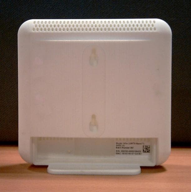
QGGIPA243BA
Nov 11, 20123G Transmitter UMTS Bands 2 and 5
Equipment Class
PCB - PCS Licensed Transmitter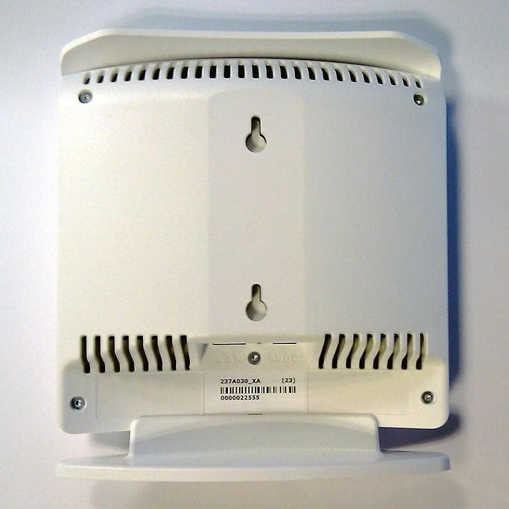
QGGIPA243B
Nov 11, 201216 user 3G Access Point operating in Bands 2 & 5
Equipment Class
PCB - PCS Licensed Transmitter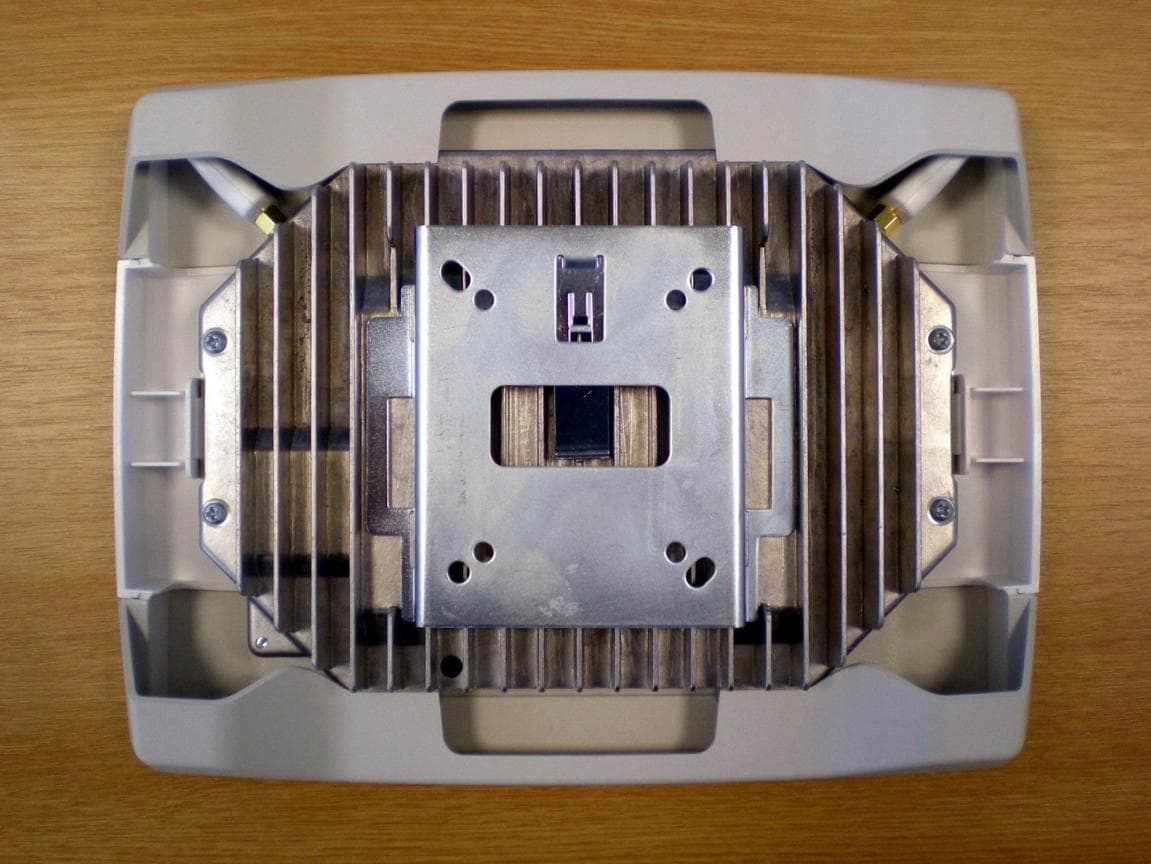
QGGIPA239B
Aug 27, 201216 user 3G Access Point operating at UMTS Bands 2 & 5
Equipment Class
PCB - PCS Licensed Transmitter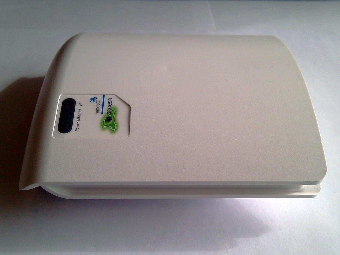
QGGIPA237CA
May 23, 20118 user 3G Access Point operating at UMTS Band 4
Equipment Class
JBP - Part 15 Class B Computing Device Peripheral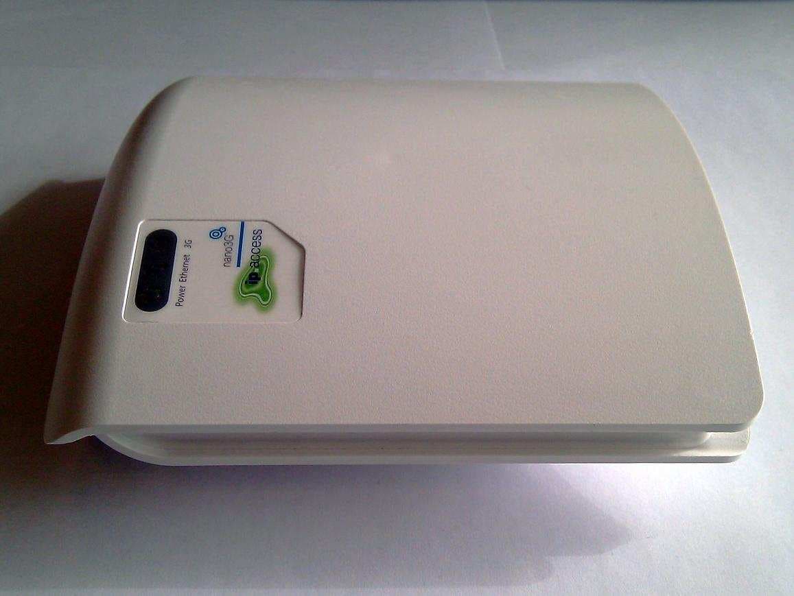
QGGIPA237C
May 23, 20118 user 3G Access Point operating at UMTS Band 4
Equipment Class
TNB - Licensed Non-Broadcast Station Transmitter