QGQ-AM241AirMAX Transceiver
Malibu Networks, Inc.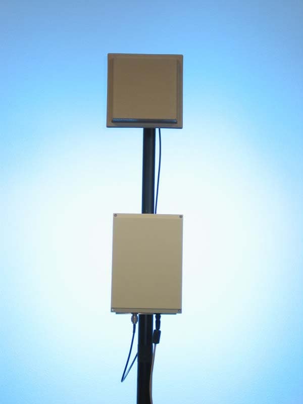
Click to zoom
Application Details
- Equipment Class
- DSS - Part 15 Spread Spectrum Transmitter
- Date of Grant
- Jul 11, 2002
- Application Purpose
- Original Equipment
- Date of Application
- Jul 11, 2002
- Equipment Note
- AirMAX Transceiver
- Frequency Range
- 2412.00000000 - 2462.00000000
- Company
- Malibu Networks, Inc.
- Country
- United States
Documents & Files
Document Text
Text extracted from the exhibit documents filed with the FCC. Open a document above to read the original.
Users Manual
AirMAX TM 240/2400 Installation & Configuration Guide July 18, 2002 P/N 8000504-000 I ii Malibu Networks AirMAX“ CPE/BTS Trademarks AirMAX TM and Malibu Networks are trademarks of Malibu Networks Inc. Windows and Microsoft are registered trademarks of Microsoft Corporation. All other trademarks are the property of their respective holders. Notice All rights reserved. All information in this manual is subject to change without notice. No part of the document may be reproduced or transmitted in any form, or by any means, electronic or mechanical, including photocopying or recording, without the express written permission of Malibu Networks Inc. FCC Emission Information This equipment has been tested and found to comply with the limits for a Class B digital device, pursuant to Part 15 of the FCC Rules. These limits are designed to provide reasonable protection against harmful interference when the equipment is operated in a residential installation. This equipment generates, uses and can radiate radio frequency energy and, if not installed and used in accordance with the instructions, may cause harmful interference to radio communications. However, there is no guarantee that interference will not occur in a particular installation. If this equipment does cause harmful interference to radio or television reception, which can be determined by turning the equipment off and on, the user is encouraged to try to correct the interference by one or more of the following measures: • Reorient or relocate the receiving antenna. • Increase the separation between the equipment and receiver. • Connect the equipment to an outlet on a circuit different from that to which the receiver is connected. • Consult the dealer or an experienced radio/TV technician for help. iii 1 FCC Radiation Hazard Warning To ensure compliance with FCC RF exposure requirements, this device must be professionally installed outdoors on a permanent structure with an antenna that is separated from all persons by a minimum of two meters. Using higher gain antennas and types of antennas not covered under the FCC certification of this product is not allowed. Installers of the radio and end users of the system must adhere to instructions provided in this manual. Safety Warning: To avoid shock, do not open or attempt to service the unit or its associated power supply. This unit is not a user serviceable device. Warning: Do not touch antennas when transmission is in progress. Possible adverse health affects can occur. Warning: When used with the ANT-24-19-D 19 dBi directional CPE antenna, the transmit power must not be set higher than 50 mW (+17 dBm). Warning: Explosive Device Proximity Warning do not operate your wireless network device near unshielded blasting caps or in an explosive environment unless the device has been modified to be especially qualified for such use. Caution: This instrument transmits radio frequency energy during normal operation. Do not stand or work in its close proximity for extended periods of time to avoid possible harmful exposure. The long-term health effects of exposure to radio frequency energy are not fully understood. WARNING WARNING WARNING WARNING CAUTION iv Malibu Networks AirMAX“ CPE/BTS Caution: When performing antenna installation and grounding, ensure that it presents no threat to people or property. Verify that the antenna mast is grounded properly and is protected from voltage surges and static charges. Observe all regional and national building and safety regulations. Contacting Malibu Networks For Information or Support 1107 Investment Blvd. Suite 250 El Dorado Hills, CA. 95762 USA Telephone: +916.941.8777 Fax: +1.916.941.8850 Web: http://www.malibunetworks.com Email: [email protected] CAUTION 1 1 Trademarks . . . . . . . . . . . . . . . . . . . . . . . . . . . . . . . . . . . . . . . . . . . . . . . . . ii Notice . . . . . . . . . . . . . . . . . . . . . . . . . . . . . . . . . . . . . . . . . . . . . . . . . . . . . ii FCC Emission Information . . . . . . . . . . . . . . . . . . . . . . . . . . . . . . . . . . . . . ii FCC Radiation Hazard Warning . . . . . . . . . . . . . . . . . . . . . . . . . . . . . . . . . iii R&TTE Compliance Statement . . . . . . . . . . . . . . . . . . . . . . . . . . . . . . . . . . iii Safety . . . . . . . . . . . . . . . . . . . . . . . . . . . . . . . . . . . . . . . . . . . . . . . . . . . . . iii Contacting Malibu Networks For Information or Support . . . . . . . . . . . . . . . iv Chapter 1 Introduction Product Overview . . . . . . . . . . . . . . . . . . . . . . . . . . . . . . . . . . . . . . . . . . . . 1 System Components . . . . . . . . . . . . . . . . . . . . . . . . . . . . . . . . . . . . . . . 2 Product Names and Numbers . . . . . . . . . . . . . . . . . . . . . . . . . . . . . . . . 5 Component Identification . . . . . . . . . . . . . . . . . . . . . . . . . . . . . . . . . . . 6 Minimum Installation Requirements . . . . . . . . . . . . . . . . . . . . . . . . . . . . . . 7 About This Manual . . . . . . . . . . . . . . . . . . . . . . . . . . . . . . . . . . . . . . . . . . . 7 Manual Conventions . . . . . . . . . . . . . . . . . . . . . . . . . . . . . . . . . . . . . . . 8 Chapter 2 Installation Before Installation . . . . . . . . . . . . . . . . . . . . . . . . . . . . . . . . . . . . . . . . . . . . 9 Installation Overview . . . . . . . . . . . . . . . . . . . . . . . . . . . . . . . . . . . . . . . . . . 11 Mounting the BTS or CPE Antenna . . . . . . . . . . . . . . . . . . . . . . . . . . . . . . 12 Mount the ODU . . . . . . . . . . . . . . . . . . . . . . . . . . . . . . . . . . . . . . . . . . . . . . 14 Connecting the Antenna to ODU . . . . . . . . . . . . . . . . . . . . . . . . . . . . . . . . 16 Connecting Ethernet and Power . . . . . . . . . . . . . . . . . . . . . . . . . . . . . . . . . 17 Chapter 3 Configuration Configuration Overview . . . . . . . . . . . . . . . . . . . . . . . . . . . . . . . . . . . . . . . 21 Initial TCP…
Text truncated - open the document above for the full version.
Cover Letter(s)
American Telecommunications Certification Body Inc. 6731 Whittier Ave, McLean, VA 22101 July 3, 2002 RE: Malibu Networks FCC ID: QGQ-AM241 After a review of the submitted information, I have a few comments on the above referenced Application. 1) Please upload an exhibit for the operational description of the device. 2) Two different models appear to be covered by this application, while only one unit was tested. Please provide detailed information regarding the differences between these models. 3) Please upload an exhibit for the external photographs of the device (please include photographs of the antennas as part of this). 4) Please note that section 4(a) of the 731 form should list either DSS or DTS as appropriate for this type of product. 5) The test report mentions that there are 2 antenna (12 dBi Omni and 19 dBi panel antenna). The report also mentions that lower gain antennas may be used. Please provide a list of all planned antenna's including type, gain, and antenna connector style of each. Please note that the manual only mentions 4 specific antennas. 6) Please provide a block diagram of the system as tested for radiated emissions. What was the cable lengths between the EUT and the antenna? Is this length always set, or is it variable? 7) Currently TCB’s are only authorize mobile classification spread spectrum transmitters in the 2.4 GHz band with both a peak conducted and peak radiated (EIRP) output power not exceeding 200 mW (see attached exclusion list). The EIRP of this transmitter with the + 12 dBi Omni & +19 dBi Panel antenna is greater than 200 mW The FCC is currently working to change or eliminate many of the restrictions on TCB’s and the latest information we have from the FCC is that they hope to publish this information shortly (see attached email regarding status of this). Options available for handling this application currently are: a) We can go forth and review the application in completion (considering the antenna's as mobile), but will have to wait until the FCC releases the changed exclusion list before we issue the grant due to the RF exposure limitations currently imposed on TCB's. b) If certain configurations that exceed the 200 mW EIRP limitation can be considered as fixed instead of mobile (distance of 2 meters between antenna and user instead of 20 cm), then we may be able to go ahead with the application now with adjustments to the MPE calculations and users manual to cover both mobile and fixed installations. If this route is selected, it will affect the suggestive use of certain MPE exhibits and the users manual information given here. Also note that if lower gain antenna's are to be used, then distinguishing information must be provided in the users manual for all types of antennas used (see #5 above as well) c) If time source based averaging can be applied this may be an additional option for still qualifying under mobile use. However this will depend on the worse case duty cycles inherent to this device and may be complicated to determine. d) Resubmit the application to the FCC. 8) Please provide information to show compliance with the antenna requirements of 15.203. Professional installation must be used if standard connectors are applied (i.e. use of a standard connector is not allowed if professional installation "may" be required or a possible option). Please note that professional installation will require a cover letter addressing the following 3 points: a) Application (or intended use) of the device b) Installation requirements c) Method of marketing the device. l Page 2July 3, 2002 Question 9 & 10 as follows are related depending on how the device is classified 9) The label on the EUT displays both the FCC ID as well as the FCC Logo. The use of the FCC logo and the phrase "for home or office use" (for products authorized under Part 15) is reserved for products authorized using a Declaration of Conformity route to compliance. Has this device also been properly tested (as given by ANSI C63.4) as a class B computer peripheral and a test report issued by an accredited test facility? If the device has met with these requirements, also please provide the DoC Statements required by 2.1077 which should be contained on a single page included in the manual or with the product and adjust the labeling information in the users manual to the information given in 15.105(b). 10) The users manual states that the device has met with Class A emissions. However the detailed product information shows residential/SOHO at one point. If the device has met with Class A emissions only, then the label should have the FCC logo and the phrase "for home or office use" removed. Also, a justification as to Class A use only should accompany the application that explains why the device will not be used in a residential area. 11) The test report states "Schematics, block diagrams, and algorithm descriptions subject to enclosed confidentiality statement". The confidentiality letter only lists schematics, block diagrams, and parts list. Please clarify which exhibits are to be held confidential and correct the confidentiality letter if necessary. Please note that the test report may not be held confidential and that any other information contained within the test report that might be considered confidential (i.e. detailed product description) should be removed from the test report and provided in a separate exhibit. 12) The test methodology (page 8 of 39) given in the test report states that the power output was measured with a power meter, however the data given on pages 12-14 appear to be from a spectrum analyzers. Please comment. Note: All of the power output results match the information contained in the plots, except 1 which is off slightly. 13) The power output tested should be performed with the RBW set to greater than the 6 dB bandwidth of the emissions. Since this is not possible on most spectrum analyzers, either a peak power meter should be used, or the power integra…
Text truncated - open the document above for the full version.
Cover Letter(s)
10 July 2002 RE: Malibu Networks FCC ID: QGQ-AM241 Mr. Johnson, On behalf of Malibu Networks I am pleased to provide you with the following answers to your inquiries. Should you have any further questions or require and clarification on any of these issues, please do not hesitate to contact me at [email protected] . Your questions are addressed below Best Regards, David Waitt 1) Please upload an exhibit for the operational description of the device. MALIBU: Please refer to the “Detailed product information” section in the test report in addition to the “AirMAX CPE – BTS Overview” document uploaded with this reply. Simply stated, the device is a “standard”, previously certified, IEEE 802.11 PCMCIA card transceiver and a single board computer (both purchased components) housed in a weatherproof enclosure that is connected to a omni- directional or directional antenna to provide an IEEE 802.11 data link. The units operates with a maximum transmit power of approximately 100mw in the unlicensed Part 15, 2.4 GHz ISM band and utilizes Direct Sequence Spread Spectrum. 2) Two different models appear to be covered by this application, while only one unit was tested. Please provide detailed information regarding the differences between these models. MALIBU: There is no significant difference between the hardware in each type of unit. Both units use the same single board computer, the same “Off the Shelf” Cisco Systems IEEE 802.11 radio module (AIR-LMC-350) that Cisco certified under FCC ID: LDK 102040 and the same enclosure. The only differences between the two units (CPE and BTS) are: -The firmware contained in the compact flash card and the size of the compact flash card -The amount of RAM on the single board computer -The antenna that is connected to the unit. The BTS will typically NOT use the 19dBi panel antenna. Since the CPE and the BTS have two different Malibu Networks model numbers, both were included in the application. 3) Please upload an exhibit for the external photographs of the device (please include photographs of the antennas as part of this). MALIBU: External pictures have been uploaded with this reply 4) Please note that section 4(a) of the 731 form should list either DSS or DTS as appropriate for this type of product. MALIBU: The equipment is DSS. Malibu Networks, Inc. 1107 Investment Blvd. Suite 250 El Dorado Hills, CA 95762 5) The test report mentions that there are 2 antenna (12 dBi Omni and 19 dBi panel antenna). The report also mentions that lower gain antennas may be used. Please provide a list of all planned antenna's including type, gain, and antenna connector style of each. Please note that the manual only mentions 4 specific antennas. MALIBU: Malibu intends on using four different antennas in the implementation of the system. They are: MaxRad 8 dBi omni - base model number: MFB24008 (down-tilt as required at particular installation) NCG Company 12 dBi omni (with 3 degree down-tilt) - model number: GP-24-3 ARC Wireless 8.5 dBi panel - model number – panel 8.5 ARC Wireless 19 dBi panel - model number – panel 19 Given these intended antennas, the highest gain of each antenna type was tested with the unit. The antenna connector of each is an ‘N’ connector. They will be connected to the BSE or CPE unit via a coax cable. The data sheets on all of the antennae were uploaded with the original application submission. 6) Please provide a block diagram of the system as tested for radiated emissions. What was the cable lengths between the EUT and the antenna? Is this length always set, or is it variable? MALIBU: The length of the cable used for the radiated emissions tests between the unit under test and the antenna was 4ft. This same length was used for all of the tests and the cable used during the tests is the type that will be shipped with the units. As this is the only cable that will be shipped with the units, the length will be constant throughout the installations. The radiated emissions test setup in the test report has been modified to show the antenna in the setup. 7) Currently TCB’s are only authorize mobile classification spread spectrum transmitters in the 2.4 GHz band with both a peak conducted and peak radiated (EIRP) output power not exceeding 200 mW (see attached exclusion list). The EIRP of this transmitter with the + 12 dBi Omni & +19 dBi Panel antenna is greater than 200 mW The FCC is currently working to change or eliminate many of the restrictions on TCB’s and the latest information we have from the FCC is that they hope to publish this information shortly (see attached email regarding status of this). Options available for handling this application currently are: We can go forth and review the application in completion (considering the antenna's as mobile), but will have to wait until the FCC releases the changed exclusion list before we issue the grant due to the RF exposure limitations currently imposed on TCB's. If certain configurations that exceed the 200 mW EIRP limitation can be considered as fixed instead of mobile (distance of 2 meters between antenna and user instead of 20 cm), then we may be able to go ahead with the application now with adjustments to the MPE calculations and users manual to cover both mobile and fixed installations. If this route is selected, it will affect the suggestive use of certain MPE exhibits and the users manual information given here. Also note that if lower gain antenna's are to be used, then distinguishing information must be provided in the users manual for all types of antennas used (see #5 above as well) If time source based averaging can be applied this may be an additional option for still qualifying under mobile use. However this will depend on the worse case duty cycles inherent to this device and may be complicated to determine. Resubmit the application to the FCC. MALIBU: We will reclassify the device as a “Fixed” device. The modified RF exposure statement appears in the revised manual on page iii 8) Please pr…
Text truncated - open the document above for the full version.
Cover Letter(s)
Regarding: Professional Installation of the AirMax 240 and the AirMAX 2400 FCC ID: QGQ-AM241 This letter outlines the justification for the Professional Installation of the AirMAX products by highlighting: Application (or intended use) of the device Installation requirements Method of marketing the device. Intended Use Of Equipment: The AirMAX™ System The Malibu Networks AirMAX System is designed exclusively for operations in the 2.4 GHz ISM band. The system is composed of base station (BTS) and customer equipment (CPE). The system is intended as a fixed wireless access system to provide IP based network connectivity, for Internet Service Providers and enterprise network applications using the IEEE 802.11 protocol. Installation requirements The installation requirements are spelled out in detail in the Users manual / Installation guide that was uploaded with this application. Please refer to the installation and configuration guide. This product, BTS and CPE will be professionally installed. Method of marketing the device This product will be sold through telecommunications equipment distributors to ISPs and Corporate IT departments. Malibu Networks, Inc. 1107 Investment Blvd. Suite 250 El Dorado Hills, CA 95762
Cover Letter(s)
To: Federal Communications Commission 7435 Oakland Mills Road Columbia, Maryland 21046 Subject: Authorization of David Waitt and Richard A. Milewski to act on our behalf and as our agent for preparation of certification applications. Gentlemen, This is a letter of authorization to accept David Waitt and Richard A. Milewski, each of whom are independent consultants who’s services have been retained by Malibu Networks, Inc. to sign applications before the commission on our behalf, to make representations to you on our behalf and to receive and exchange data between our company and the Commission in connection with the certification of the following Telemics product(s): Malibu Networks AirMax 240 Malibu Networks AirMax 2400 Under FCC Docket number 20780 and General Docket Number 80-284 pursuant to Part 15 of the FCC Rules and Regulations. If you have any further questions or need additional information, please feel free to contact me at 408- 293-5525. 29 June 2002 James Allen Date Executive Vice President and Chief Operating Officer Malibu Networks, Inc. 1107 Investment Blvd. Suite 250 El Dorado Hills, CA 95762
Cover Letter(s)
To: Federal Communications Commission 7435 Oakland Mills Road Columbia, Maryland 21046 Subject: Confidentiality Request for Certification Application Gentlemen, On behalf of Malibu Networks, Inc. I request that the following documents associated with the Part 15 Certification application for FCC ID: QGQ-AM241 be withheld from public disclosure per Section 0.459 of the FCC Rules. All circuit schematics. All electrical block diagrams All Parts Lists This request is made under the provisions of Section 0.457(d) of the FCC rules and Sections 552(b)(4) of the Freedom of information Act. These Sections authorize withholding from public inspection, materials which would be privileged as a matter of law if retained by the person submitting them in addition to materials, which would not customarily be released to the public, by that person. If you have any questions, please do not hesitate to contact me at: [email protected] or (408) 832-7053 Sincerely, David Waitt Consultant Malibu Networks, Inc. 1107 Investment Blvd. Suite 250 El Dorado Hills, CA 95762
External Photos
Malibu Networks, AirMAX Installation / Antenna photos. FCC ID QGQ-AM241 AirMAX with 12 dBi Omni AirMAX with 8 dBi Omni AirMAX with 19 dBi Panel AirMAX with 8 dBi Panel
External Photos
Malibu AirMAX External Photos FCC ID QGQ-AM2 Front / Top Right Side Back / Top Left Side Bottom / Front
ID Label/Location Info
Part Number: Revision Drawn by:R. MilewskiDate:6/30/2002 Approved:R. MilewskiDate:6/30/2002 Released:R. MilewskiDate:6/30/2002 Last Rev:Date: Malibu Networks, Inc. 1107 Investment Blvd. Suite 250 El Dorado Hills, CA 95762 Title: Serial Number & FCC Label Placement Diagram 2300501-000 A Notes: 1) Box and cover set cover set MN Part Number 2300500-000, Rose+Bopla Aluform Part Number 04142807-00, painted gray. 2) Position Serial Number & FCC Label 1/4 inch from box edge, centered on long axis of box. 3) Label must be clear of pole mounting brackets and visible when box is mounted on poles of up to 3 inches diameter. Serial Number & FCC Label
ID Label/Location Info
AirMAX 2400 2.4 GHz DS Fixed Wireless Access BTS 206310001 Model AirMAX 240 • Version B • P/N: 2000501-000 See manual before use FCC ID: QGQ-AM241 For home or office use. This device complies with part 15 of the FCC Rules. Operation is subject to the following two conditions: (1) This device may not cause harmful interference, and (2) this device must accept any interference received, including interference that may cause unwanted operation. Label 8330501-002 B
ID Label/Location Info
AirMAX 240 2.4 GHz DS Fixed Wireless Access CPE 205310001 Model AirMAX 240 • Version B • P/N: 2000500-000 See manual before use FCC ID: QGQ-AM241 For home or office use. This device complies with part 15 of the FCC Rules. Operation is subject to the following two conditions: (1) This device may not cause harmful interference, and (2) this device must accept any interference received, including interference that may cause unwanted operation. Label 8330500-002 B
Internal Photos
Malibu Networks, Inc. 1107 Investment Blvd. Suite 250 El Dorado Hills, CA 95762 Internal Product Photos For Malibu Networks AirMax 240 / 2400 FCC Part 15 Certification Application FCC ID: QGQ-AM241 Malibu Networks AirMAX 240 / 2400 Malibu Networks AirMAX 240 / 2400 Malibu Networks AirMAX 240 / 2400 Internal IEEE 802.11 Cisco PCMCIA Card
Operational Description
Malibu Networks is pleased to introduce the Malibu Networks AirMAX system designed exclusively for point-to-multipoint operations in the 2.4 GHz ISM band. The system is composed of a BTS, CPE, a full featured Service Management System (SMS) and Malibu Networks' patent pending QoS implementation, MAXimum IP. With the benefits of MAXimum IP a service provider will see an immediate, dramatic increase in their bottom line. MAXimum IP accomplishes this through two primary means. First, by employing MAXimum IP the efficiency of the system is increased resulting in a subscriber throughput improvement of at least 2 times the effective bandwidth as compared to similar systems without MAXimum IP. Second, MAXimum IP offers considerably more than just minimum and maximum bandwidth control per CPE as well as per each subscriber behind the CPE, a claim no other vendor can make today. Maximum IP also gives the service provider the ability to control jitter and latency as well - enabling additional high value services to be sold and supported. Real time traffic such as voice and gaming can now be offered to the end user. Combined with the full featured SMS for services and subscriber definition, the service provider can easily create, package and sell an expanded set of services never before available in a system at this price point. The CPE and BTS portions of the system are all outdoor units (ODU) ruggedized for the harshest environments with an operating temperature range of up to 160 degrees F. With this approach, installation times are reduced and the skill-set required is substantially reduced. Reliability and cost effectiveness were key design goals for this system. By utilizing standard, off-the-shelf components Malibu Networks achieves both of these goals. Malibu Networks' product is reliable and takes advantage of volume production resulting in a access solution that outperforms other competitive solutions on a cost/benefit scale. Malibu Networks AirMAX System: 2.4 GHz BTS and CPE TM TM The Technology is MAXimum IP. The Product is AirMAX. Specification Performance Operating Frequency 2.4 -2.483 GHz ISM Data Rate per sector 11Mbps Non-overlapping channels 3 CPE's per Sector 100 Subscribers per CPE Up to 100 Range Up to 20 km System Specification Performance Waveform DSSS Duplexing TDD Modulations BPSK, QPSK, CCK Power Output Up to 20dBm Receive Sensitivity at BER 10-6 - 94 dBm @ 1 Mbps - 91dBm @ 2 Mbps - 89 dBm @ 5.5 Mbps - 85 dBm @ 11 Mbps RF Specification Performance Protocols Supported Static IP, NAT, DHCP Server, SNMPv2 Interfaces 10/100BaseT Security Rule based packet filtering 128 bit WEP with Dynamic Key Exchange Networking & Security Specification Performance Implementation Per flow queuing and scheduling, fair and dynamic bandwidth allocation Traffic Shaping and Policing Delay and Jitter control Class of Service Guaranteed, Controlled and Best Effort Packet Classification Layer 3 and layer 4 classification including TOS and RTP payload QoS Specification Performance Temperature Range -20 to +70 °C Operational Temp Range Power - Supply- Consumption 100-240VAC, 50-60Hz, 1.5 amps maximum Mounting 1" to 2" pole mount Dimensions 11"(h) x 8"(w) x 3"(d) Physical and Environmental © 2002 Malibu Networks. AirMAX System Datasheet. Information subject to change without notice. rev 061302 Malibu Networks 1107 Investment Blvd Suite 250 El Dorado Hills, CA 95762 (916) 941-8777 [email protected] www.malibunet.com Feature AirMAX SMS Base station management interfaces Command line interface , GUI-based SMS, SNMP Agent CPE management interfaces Web browser-based GUI Management protocol SNMP v2, with multiple community strings MIBs MIB II, 802.11, Malibu enterprise MIB Open interfaces Provisioning, accounting, and billing applications Base station software management Download across network CPE software management Download across network AirMAX Element Management and Provisioning
Operational Description
2.45 GHz Panel Antennas 2.45 GHz Panel Antennas Electrical (typical)Panel 8.5dBiPanel 13dBiPanel 19dBi Frequency 2.45 GHz2.45 GHz 2.45 GHz Gain8.5dBi13dBi19dBi PolarizationLinearLinearLinear Antenna designSingle patchFour patchSixteen patch Bandwidth - 1.5:1 VSWR100 MHz100 MHz100 MHz Horizontal beamwidth60º38º18º Vertical beamwidth60º38º18º Cross polarization>30dB>30dB>30dB Maximum power input watts100100100 Front-to-back ratio>30dB>30dB>30dB Efficiency85%75%70% ConnectorsSMA female,SMA female,N female TNC female,TNC female, N femaleN female Lightning protectionDirect groundDirect groundDirect ground Mechanical Width - in (cm)5.15 (13.1) 8.5 (21.6)15.5 (39.4) Height - in (cm)5.15 (13.1)8.5 (21.6)15.5 (39.4) Depth - in (cm).82 (2.1)1.125 (2.8)1.125 (2.8) Case materialHigh impact UVHigh impact UVHigh impact UV stabilized plastic,stabilized plastic,stabilized plastic, ultrasonically weldedultrasonically weldedultrasonically welded Case colorWhiteGray, other colors available on customer order Wind/ice loading area - in 2 (cm 2 )26.5 (171)72 (466)240 (1552) Lateral thrust @100 mph - lbs (kg)5 (11)10 (22) 15 (33) Torsional moment @ 100 MPH with standard mounting - ft/lbs (m/kg)0.1 (0.22)0.2 (0.22)0.4 (0.88) ➢Complete line of planar antennas ➢Flat design provides high efficiency and low back lobes with minimal depth dimension ➢Allowed in covenant controlled areas ➢Easy installation saves time and money ➢Mounting brackets included ➢Protected from the environment (ice loading and wildlife) ➢Supports all applications from 2.4 to 2.5 GHz (ISM, Home RF, 802.11b, . 4860 Robb St., Suite 101 •Wheat Ridge, CO 80033 •303.421.4063 •FAX: 303.424.5085 •www.antennas.com For more information e-mail [email protected] or call sales 800.508.6532 Features Specifications Antennas America ™ ProSht.2.45+bk.btn 3/8/02 2:21 PM Page 1
Operational Description
GP-24-3 12dB gain omni With 3-degree electrical downtilt Page 3 of 72.4 Antenna Systems 6/28/2002http://www.cometantenna.com/2point4.html Page 4 of 72.4 Antenna Systems 6/28/2002http://www.cometantenna.com/2point4.html
Operational Description
51 An ISO-9001 Registered Company General Specifications: Omnidirectional Base Station Antennas Radome Material: 5/8 inch diameter pultruded UV-stable fiberglass Polarization: Vertical Nominal Impedance: 50 ohms Mounting Base Diameter: 1-1/4 inches Mounting Method (sold separately): MMK1924 L-bracket mount for wall or pipe mount (not recommended for use with model M5B24010) MMK8 - Aluminum extruded bracket fo…
Text truncated - open the document above for the full version.
Contact Information
Applicant
Richard A Milewski(Project Manager)
Technical Contact
Non-Technical Contact
-David Waitt
[email protected]408-832-7053
Test Firm
Elliott Laboratories LLCDavid Bare
Technical Specifications
| # | Rule Parts | Frequency Range | Power Output |
|---|---|---|---|
| 1 | 15C | 2.41 GHz - 2.46 GHz | 117.50 mW |
Other Applications from Malibu Networks, Inc.
QGQ-AM581
Nov 21, 2002Digital Microwave Fixed Link
Equipment Class
DTS - Digital Transmission System