QGQ-AM581Digital Microwave Fixed Link
Malibu Networks, Inc.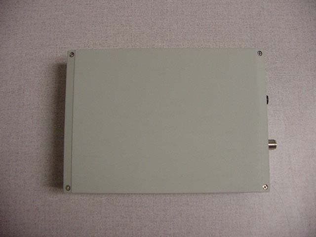
Click to zoom
Application Details
- Equipment Class
- DTS - Digital Transmission System
- Date of Grant
- Nov 21, 2002
- Application Purpose
- Original Equipment
- Date of Application
- Nov 21, 2002
- Equipment Note
- Digital Microwave Fixed Link
- Frequency Range
- 5750.00000000 - 5800.00000000
- Company
- Malibu Networks, Inc.
- Country
- United States
Documents & Files
Document Text
Text extracted from the exhibit documents filed with the FCC. Open a document above to read the original.
Users Manual
AirMAX TM 580/5800 Installation & Configuration Guide November 20, 2002 P/N 8000505-000 B ii Malibu Networks AirMAX™ 580/5800 CPE/BTS Trademarks AirMAX TM and Malibu Networks are trademarks of Malibu Networks Inc. Windows and Microsoft are registered trademarks of Microsoft Corporation. All other trademarks are the property of their respective holders. Notice All rights reserved. All information in this manual is subject to change without notice. No part of the document may be reproduced or transmitted in any form, or by any means, electronic or mechanical, including photocopying or recording, without the express written permission of Malibu Networks Inc. FCC Emission Information This equipment has been tested and found to comply with the limits for a Class B digital device, pursuant to Part 15 of the FCC Rules. These limits are designed to provide reasonable protection against harmful interference when the equipment is operated in a residential installation. This equipment generates, uses and can radiate radio frequency energy and, if not installed and used in accordance with the instructions, may cause harmful interference to radio communications. However, there is no guarantee that interference will not occur in a particular installation. If this equipment does cause harmful interference to radio or television reception, which can be determined by turning the equipment off and on, the user is encouraged to try to correct the interference by one or more of the following measures: • Reorient or relocate the receiving antenna. • Increase the separation between the equipment and receiver. • Connect the equipment to an outlet on a circuit different from that to which the receiver is connected. • Consult the dealer or an experienced radio/TV technician for help. iii 1 FCC Radiation Hazard Warning To ensure compliance with FCC RF exposure requirements, this device must be professionally installed outdoors on a permanent structure with an antenna that is separated from all persons by a minimum of two meters. Using higher gain antennas and types of antennas not covered under the FCC certification of this product is not allowed. Installers of the radio and end users of the system must adhere to instructions provided in this manual. Safety Warning: To avoid shock, do not open or attempt to service the unit or its associated power supply. This unit is not a user serviceable device. Warning: Do not touch antennas when transmission is in progress. Possible adverse health affects can occur. Warning: Explosive Device Proximity Warning—do not operate your wireless network device near unshielded blasting caps or in an explosive environment unless the device has been modified to be especially qualified for such use. Caution: This instrument transmits radio frequency energy during normal operation. Do not stand or work in its close proximity for extended periods of time to avoid possible harmful exposure. The long-term health effects of exposure to radio frequency energy are not fully understood. Caution: When performing antenna installation and grounding, ensure that it presents no threat to people or property. Verify that the antenna mast is grounded properly and is protected from voltage surges and static charges. Observe all regional and national building and safety regulations. WARNING WARNING WARNING CAUTION CAUTION iv Malibu Networks AirMAX™ 580/5800 CPE/BTS Contacting Malibu Networks For Information or Support 1107 Investment Blvd. Suite 250 El Dorado Hills, CA. 95762 USA Telephone: +1.916.941.8777 Fax: +1.916.941.8850 Web: http://www.malibunetworks.com Email: [email protected] v 1 Trademarks . . . . . . . . . . . . . . . . . . . . . . . . . . . . . . . . . . . . . . . . . . . . . . . . .ii Notice . . . . . . . . . . . . . . . . . . . . . . . . . . . . . . . . . . . . . . . . . . . . . . . . . . . . .ii FCC Emission Information . . . . . . . . . . . . . . . . . . . . . . . . . . . . . . . . . . . . .ii FCC Radiation Hazard Warning . . . . . . . . . . . . . . . . . . . . . . . . . . . . . . . . .iii Safety . . . . . . . . . . . . . . . . . . . . . . . . . . . . . . . . . . . . . . . . . . . . . . . . . . . . .iii Contacting Malibu Networks For Information or Support . . . . . . . . . . . . . .iv Chapter 1: Introduction Product Overview . . . . . . . . . . . . . . . . . . . . . . . . . . . . . . . . . . . . . . . . . . . .1 System Components . . . . . . . . . . . . . . . . . . . . . . . . . . . . . . . . . . . . . . .2 Product Names and Numbers . . . . . . . . . . . . . . . . . . . . . . . . . . . . . . . .5 Component Identification . . . . . . . . . . . . . . . . . . . . . . . . . . . . . . . . . . .6 Minimum Installation Requirements . . . . . . . . . . . . . . . . . . . . . . . . . . . . . .7 About This Manual . . . . . . . . . . . . . . . . . . . . . . . . . . . . . . . . . . . . . . . . . . .7 Manual Conventions . . . . . . . . . . . . . . . . . . . . . . . . . . . . . . . . . . . . . . . . . .8 Chapter 2: Installation Before Installation . . . . . . . . . . . . . . . . . . . . . . . . . . . . . . . . . . . . . . . . . . . .9 Installation Overview . . . . . . . . . . . . . . . . . . . . . . . . . . . . . . . . . . . . . . . . . .11 Mounting the BTS or CPE Antenna . . . . . . . . . . . . . . . . . . . . . . . . . . . . . .12 Omnidirectional Antenna Mounting . . . . . . . . . . . . . . . . . . . . . . . . . . . .13 CPE Directional Antenna Mounting . . . . . . . . . . . . . . . . . . . . . . . . . . .16 Mount the ODU . . . . . . . . . . . . . . . . . . . . . . . . . . . . . . . . . . . . . . . . . . . . . .17 Connecting the Antenna to ODU . . . . . . . . . . . . . . . . . . . . . . . . . . . . . . . .19 Connecting Ethernet and Power . . . . . . . . . . . . . . . . . . . . . . . . . . . . . . . . .20 Chapter 3: Configuration Configuration Overview . . . . . . . . . . . . . . . . . . . . . . . . . . . . . . . . . . . . . . .23 Initial TCP/IP Configuration . . . . . . . . . . . . . . . . . …
Text truncated - open the document above for the full version.
Block Diagram
Up/down Converter PLL Tx Detect/Switch Driv er and PA ga te TR 802.11b Radio Cisco LMC352 Controller PCB Compact Flash Serial Port Boot ROM - 64 kByte SDRAM 16/64 MByte Clocks - 33 MHz, 32 kHz AMD Elan SC520 PCI Bus PCMCIA CardBus Ethernet PHY/MAC RJ - 45 10/100BaseT 18 to 60 VDC Enclosure Antenna PoE (Power-over-Ethernet) Part Number: Revision Drawn by:L. CrawfordDate:8/17/2002 Approved:L. CrawfordDate:8/17/2002 Released:L. CrawfordDate:8/17/2002 Last Rev: Malibu Networks, Inc. 1107 Investment Blvd. Suite 250 El Dorado Hills, CA 95762 Title: AirMax-580/AirMax-5800 Block Diagram 8610510-000 A AirMax 580 CPE / AirMax-5800 BTS 2.4 GHz 5.8 GHz
Block Diagram
Page 1 of 2 2.4 to 5.8 GHz Up/Down Converter Module Block Level Schematic Malibu Networks Part Number 2110501-000 Tx Detect PA Gate T/R Sw Drive VCO TCXO 1 2 3 4 5 T/R 5.8 GHz to Antenna T/R 2.4 GHz to WLAN Radio Card T Used on Malibu Networks AirMax 580-B and AirMAX 5800-B Supplier: Teletronics Supplier Part Number: UDC 5800 DC Regulation 6 PLL 1107 investment blvd, suite 250 el dorado hills, ca 95762 tel: 916 941 8777 fax: 916 941 8850 Malibu Networks 2.4 to 5.8 GHz Up/Down Converter Module Page 2 of 2 Block Level Schematic Functional Description 1 Overview Functional Description: The 2.4 to 5.8 Up/Down Converter (UDC) is utilized in Malibu Networks’ AirMax 580 and 5800 model products. The UDC is supplied as a module by Teletronics, Inc. to Malibu Networks, Inc. The UDC’s primary functions are: 1.1 Block frequency upconvert and amplify 2.4 GHz 802.11b modulated carriers sourced from a WLAN card to the 5.8 GHz U-NII Band for transmission over-the-air 1.2 Block frequency downconvert and amplify 5.8 GHz the modulated carriers received over-the- air in the 5.8 GHz U-NII Band to a 2.4 GHz WLAN card. 2 Detailed Functional Description (Please Refer to accompanying block schematic diagram) 2.1 Circuit Group (1) – Phased Locked Loop Voltage Controlled Local Oscillator and Local Oscillator Distribution 2.1.1 VCO is sampled, divided and phase comparison performed to derive VCO tune voltage proportional to frequency error difference of VCO and TCXO. TCXO is specified such that the Local Oscillator Frequency (and consequent up and downconverted carrier frequencies) is held to within +/- 2 PPM over the product operating temperature range. The PLLVCO is fixed frequency type at 3.328 GHz and not tuned. 2.1.2 The PLLVCO output is buffered, split and amplified to drive the mixers in the transmit block (2) and receive block (3). 2.2 Circuit Group (2) – Upconverter 2.2.1 2.4 GHz modulated carriers arrive at the input to the Upconverter on the left side of the diagram. When a carrier is present at this interface, the UDC is automatically placed in transmit mode by block (4), described more in detail later in this document. 2.2.2 The incoming 2.4 GHz carriers are mixed with the 3.328 GHz LO and the 5.8 GHz product is selected by filtering. 2.2.3 The Upconverted signal is amplified to achieve the required transmitter output power. 2.2.4 The Transmitter gain is temperature compensated 2.2.5 No power control is performed on the UDC. Power control is achieved via controls to the WLAN radio. 2.2.6 Upconverted carriers are directed to the antenna by the T/R switch at the right side of the diagram. 2.3 Circuit Group (3) - Downconverter 2.3.1 5.8 GHz carriers arrive at the antenna interface on the right side of the diagram. 2.3.2 The received 5.8 GHz carriers are directed to the downconverter by the T/R switch. 2.3.3 The received carriers are amplified, filtered and mixed with the LO of 3.328 GHz and further filtered to select the desired 2.4 GHz product. 2.3.4 The received carriers are directed to the WLAN radio via the T/R switch at the left side of the diagram. 2.4 Circuit Group (4) – Transmit Detection and Driver 2.4.1 When 2.4 GHz carriers are presented to the UDC from the WLAN card, they are sampled, detected, amplified and compared to a reference voltage. 2.4.2 In the presence of a 2.4 GHz carrier presented to the UDC, the transmit detector drives both T/R switches to direct the signal through the transmitter (2) and on to the antenna interface. 2.4.3 The transmit detector also gates the final PA stage “on” (transmit mode) when the 2.4 GHz carrier from the radio card is present and “off” (receive mode) when there is no carrier presented by the radio card. 2.5 Circuit Group (5) – Coarse Transmit Power Set Attenuator 2.5.1 This attenuator is factory selected to during final test to set the transmit output power matching the nominal radio output power and gain of the transmitter to achieve the desired transmit power. 2.5.2 Fine channel-to-channel power flatness is further calibrated out during final test via software setting of the WLAN radio drive level. 2.6 Circuit Group (6) – DC Regulation – Provides local DC voltage regulation for all UDC functions.
Cover Letter(s)
From: Nusrat Jamal [[email protected]] Sent: Wednesday, November 13, 2002 8:22 PM To: [email protected] Subject: Schmatics for UDC 5800 for FCC filing Dear Mr. Gubisch Attached please find the schematics for our frequency converter model UDC5800 Rev F. I was asked by Mr. Ray Vallejo to send these files to you direct. These schematics are Teletronics confidential property and must not go to public domain. I therefore request to maintain this confidentiality. If you need any other document or you have any questions please do contact me. best regards Nusrat Jamal Vice President Teletronics International Inc. 1803 Research Blvd. Suite 404 Rockville, MD 20850 301-309-8500 Fax 301-309-8851 www.teletronics.com
Cover Letter(s)
To: [email protected]; [email protected] Cc: [email protected]; [email protected] Subject: RE: Malibu FCC ID: QGQ-AM581 Jas: Thank you for confirming FCC ID of module. 1) We will continue review while waiting for #1. 2) OK 3) FCC label did not appear to be identified as such in label photo provided, please confirm that attachment is correct. Regards, Roland Gubisch ITS -----Original Message----- From: [email protected] [mailto:[email protected]] Sent: Sunday, November 17, 2002 2:17 AM To: [email protected]; [email protected] Cc: [email protected]; [email protected] Subject: Re: Malibu FCC ID: QGQ-AM581 Roland: Thank you for the prompt reply. Yes, Malibu is having FCC approved device AIR-LMC350 manufactured by Cisco. It is FCC ID: LDK 102040 and CSA 246 1103 2079A. Malibu FCC ID: QGQ-AM241 and grant is attached for your review. Requested documents: 1. Operational description is under request and will be sent to you asa I receive. 2. No additional docs required. 3. Label location picture was enclosed in External picture package and I have attached again for your review. I will appreciate your help to expedite this grant. Regards, Jas
Cover Letter(s)
From: Larry Crawford [[email protected]] Sent: Wednesday, November 20, 2002 7:17 PM To: 'Roland Gubisch ITS/ES-Box' Subject: RE: FCC ID: QGQ-AM581 - Final issues Hi Roland: Pleae find attached updated installation manual. All references to 8 dBi antenna, power set access/instructions have been removed to reflect product tested. Also added antenna cable component and loss to "Product Names and Numbers". Please let me know ASAP if you require anything else. Thanks for your help, Larry ++++++++++++++++ Larry Crawford Director of Engineering Malibu Networks, Inc. 1107 Investment Blvd. Suite 250 El Dorado Hills, CA 95762 805-340-2504 mobile, best access/messages 508-632-8186 home office efax 916-941-8777 EDH main office 916-941-8850 EDH fax -----Original Message----- From: Roland Gubisch ITS/ES-Box [mailto:[email protected]] Sent: Wednesday, November 20, 2002 8:55 AM To: 'Jas Dhaliwal @icacorp' Subject: FCC ID: QGQ-AM581 - Final issues Jas: Regarding the Installation Manual: ! It refers to four antennas: 8 omni, 10 omni, 11 directional and 14 directional dBi. The test report refers to only three: 10 omni, 13 directional and 14 directional dBi. The FCC instructions for TCB review state: "Measurements should also be made on the lowest gain antenna, so that the EUT is operating at its highest available output power, in order to test for case radiation." This would require the 8 dBi omni to be tested. Please indicate if the 8 dBi antenna will be available, and if so why it was not tested. 2) it refers to a maximum output power of 160 mW; the highest measured output power according to the test report is 113 mW. Please comment. 3) There is no information in the Installation Manual indicating what maximum power settings should be selected for each antenna. Please comment. The FCC instructions for TCB review state: "The installation Manual must contain adequate instructions such that the correct transmit power can be chosen for any antenna being used." Thank you, Roland Gubisch ITS
External Photos
External Photos FCC ID: QGQ-AM581
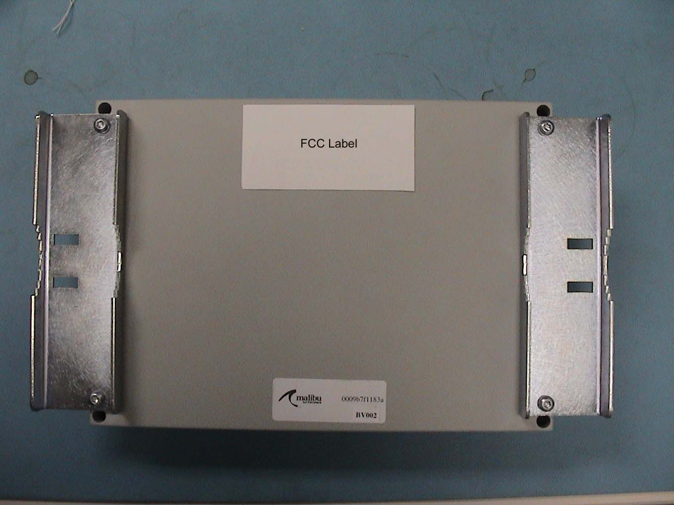
ID Label/Location Info
7/19/20027/19/20027/19/2002 ITE Label P/N 8330510-000 Rev A Title: Label, AirMAX 580/5800 Regulatory Part Num ber: Revision:Drawn By:Approved:Released:Material: Bill D.Bill D.Bill D.UL app mylar for outdoor applications white with black letters Date:Date:Date: A 8330510 - 000 Malibu Networks, Inc. 1107 Investment Blvd. Suite 250 El Dorado Hills, CA 95762 Bold Arial Narrow 8 point font first/second line, third line 10 point font. Statement on bottom portion of label is 8 point font Arial Narrow. Malibu Logo and other icons size as shown (sample label supplied) 2.0” 4.0 ” Model AirMAX 580/5800 Input Rating: 24VDC, 2.0 Amps max FCC ID: Q G Q -AM581 E230207 This device complies with part 15 of the FCC rules. Operation is subject to the following two conditions: (1) This device m ay cause harmful interference and (2) This device must accept any interference received including interference that may cause undesired operation. Made in the USA with parts of domestic and foreign origin.
Internal Photos
Internal Photos FCC ID: QGQ-AM581
Operational Description
Features AirMAX™ 580/5800 Systems • Quality of Service ⇒ Per-flow queuing and scheduling ⇒ Fair and dynamic bandwidth allocation ⇒ Traffic shaping and policing ⇒ Classes of Service ⇒ Packet Classification at Layer 3/4 ⇒ Supports Real-time Voice/Video • Management ⇒ CLI, SNMP and GUI management interfaces ⇒ Multi-tiered Service Management ⇒ Subscriber Management ⇒ Service level Agreement Support ⇒ Static IP, DHCP server, and NAT ⇒ Per subscriber, per service and per CPE accounting ⇒ System Configuration ⇒ Multiple Supported MIBS ⇒ Remote Software Updates • Security ⇒ Operator Security ⇒ Rule-based Packet Filtering ⇒ 128bit WEP with Dynamic Key Exchange • Robust Hardware ⇒ Proven off-the-shelf components ⇒ Malibu value-added software and integration for an unparalleled feature set ⇒ Ruggedized chassis and antennas ⇒ Simple Installation Malibu Network’s AirMAX™ systems offer unprecedented wireless broadband access services in the 5.725 to 5.825 GHz band, with a robust system architecture, and a full palette of system features. AirMAX is ideal for providing broadband access to businesses and residences, including multi-dwelling units. Each AirMAX system is composed of a Base Station (BTS), one or more Customer Premises units (CPE), cables and antennas. Also included are Malibu’s patent pending QoS implementation— Maximum IP ,™ SNMP and CLI management tools, and a full featured optional Service Management System (SMS) for managing large networks with many subscribers. The 5.8 GHz system is constructed with AirMAX 5800 BTS and 580 CPE(s). The CPE and BTS portions of the system are all out- door units (ODU), ruggedized for the harshest environ- ments with an operating temperature range of up to 55 degrees C. With these features and Malibu’s easy to use configuration software, installation times are quick, requiring no special skills. System Options: •Power-over-Ethernet Cables PoE-25: 25 ft. Power-over-Ethernet cable PoE-50: 50 ft. Power-over-Ethernet cable PoE-100: 100 ft. Power-over-Ethernet cable PoE-150: 150 ft. Power-over-Ethernet cable PoE-200: 200 ft. Power-over-Ethernet cable PoE-250: 250 ft. Power-over-Ethernet cable •SMS: Service Management System 5.8 GHz Products AirMAX 5800-B BTS AirMAX 580-B CPE ANT-58-11-D 11 dBi Directional CPE Antenna ANT-58-14-D 14 dBi Directional CPE Antenna ANT-58-8-O 8 dBi Omni BTS Antenna ANT-58-10-O 10 dBi Omni BTS Antenna ANT-58-14-S, 120 degree Sector BTS Antenna Malibu Networks • 1107 Investment Blvd, El Dorado Hills, CA 95762 USA • Tel: +1-916-941-8777 • www.malibunetworks.com Omnidirectional and Directional 2 Malibu Networks AirMAX™ Systems Standard Ethernet Cable from Customer LAN (data only) with RJ45 Connector AC Adapter connects to 110/220VAC (actual appearance may vary) Ethernet to Outdoor (ODU-side) Ethernet to Indoor RJ45 RJ45 Power DETAIL INDOOROUTDOOR Outdoor Unit (ODU) Shown Mounted On Mast Power-Over-Ethernet Cable (PoE) Antenna Cable Power Injector Note: Antennas and brackets vary based on applica- tion Base Station Per Cell CPE Subscriber Device Application SMS BTS-1BTS-2BTS-n Cell-1 CPE-1 CPE-2 CPE-3 CPE-4 CPE-n Sub-1 Sub-2 Sub-3 Sub-4 Sub-n Dev-1 Dev-2 Dev-3 Dev-4 Dev-n Appl-1 Appl-2 Appl-3 Appl-4 Appl-n Provides service to a building; e.g., a residence, Multi-Dwelling-Unit (MDU), or business A user or group of users that are managed as a single entity. A business, family, division of a business, etc. An IP device such as a PC, server, IP phone, VoIP gateway, etc. An application running on the IP device, typically associated wtih a port MAXimum IP™ Service Management System Cell-n Cell-2 AirMAX System Components (same for CPE and BTS) —Antennas and Mounting Brackets Vary Based on Application Components of an AirMAX Cellular Deployment 3 Malibu Networks AirMAX™ Systems AirMAX™ + MAXimum IP™ With AirMAX’s MAXimum IP, a service provider increases their bottom line immediately. This happens because more subscribers can be supported per unit of bandwidth, with value added and differentiated ser- vices made possible by MAXimum IP. MAXimum IP provides minimum and maximum bandwidth control per CPE and per subscriber behind the CPE—a claim no other vendor can make today. But AirMAX with MAXimum IP does much more—providing control of jit- ter and latency per application flow. This capability enables real time traffic like voice to share bandwidth with normal data. With the capabilities of AirMAX an MAXimum IP, the service provider can define service offerings just right for their customers. Add the optional SMS application and you can also have integrated creation, control and accounting for a rich set of customer services—capa- bilities never before available in a system at this price point. SMS can support multiple base stations and thousands of CPEs and subscribers. MAXimum IP Features • No loss of usable bandwidth due to collisions or contention resolution, meaning more users at higher real data rates • Ability to offer performance related SLAs in the access domain • Quality of Service –Per-flow queuing and scheduling –Fair and dynamic bandwidth allocation –Traffic Shaping and Policing • Min. and Max. Bandwidth Management • Delay and Jitter Control –Multiple Classes of Service • Guaranteed, Controlled and Best-Effort Traffic –Packet classification at Layer 3 and Layer 4 • Source and Destination IP Addresses • Source and Destination Ports • Protocol Type • TOS • RTP Payload Type –Supports Real-Time Voice and Video Traffic AirMAX Management and Security AirMAX provides powerful remote management fea- tures and a secure infrastructure to keep hackers and unintended visitors out of your network. Features include: Management Features • A variety of management user interfaces to better fit your administrative staff. Interfaces include: —Command Line Interface —SNMP —GUI based Centralized Management System —Optional Malibu Networks SMS • Multi-Tiered Service Management • Subscriber Management • Service Level Agreement Support • Static IP, DHCP Serve…
Text truncated - open the document above for the full version.
Operational Description
2360 10dB 5.8 Ghz Omni Directional Antenna The 2360 is a vertically polarised high gain base station antenna designed for use in high density RF envirnments. The excellent radiation characteristics are the distinguishing features of these well priced antennas. The antennas do have a small directional quality and this is high-lighted on the antenna radome.This is useful for preferential coverage areas. Electrical SpecificationMechanical Specifications Gain10dBLength67cm VSWR1 : 1.8Diameter7 cm PolarizationverticalWeight1.8kg Power Rating 100WWindage(at 125mph)100 lbs Elevation Beamwidth10 degreesMounting Pipe5 cm pipe Cross Pol. Discrimination 26dB min Impedance 50 ohmsMaterials Termination Fixed N- female Radiating ElementsCopper co-linear array RadomePVC white ClampsHDG steel + Stainless Steel Bolts 10 dB omni elevation co-polar 0-180 degrees 5.8 Ghz -30 -25 -20 -15 -10 -5 0 5 0102030405060708090100 110 120 130 140 150 160 170 180 degrees dB elevation co-polar 10 dBi Omni elevation co-polar -15 to +15 degrees 5.8Ghz -15 -10 -5 0 5 10 15 01234567891011121314151617 dB degrees elevation co-polar elevation co-polar
Operational Description
Stella Doradus Ireland Ltd. 12010V 5.8Ghz Base Station antenna The 12010V is a base station point to point antenna designed for use in high density RF envirnments. The excellent radiation characteristics are the distinguishing features of these well priced antennas. This family of antennas is designed for high wind harsh envirnments. Electrical SpecificationMechanical Specifications Gain13dBi 3dB beam Pattern120º x 15ºLength49cm Bandwidth5.75-5.85GhzWidth17cm VSWR1.4 : 1Depth9 cm Front to Back Ratio 30dBWeigth2.1Kg PolarizationverticalWindage(at 125mph)53lbs Power Rating 100WMechanical Tilt0-25 degrees Impedance 50 ohmsMounting Pipe5 cm pipe Termination N-Male pigtailMaterials Cross Pol. Discriminatio n25dB Radiating ElementBeam forming PCB slot array Radome ( feed )ABS Grey ClampsHDG steel + galvanised steel bolts 5.8Ghz 12010V base station antenna Azimuth -50 -45 -40 -35 -30 -25 -20 -15 -10 -5 0 -180 -170 -160 -150 -140 -130 -120 -110 -100 -90 -80 -70 -60 -50 -40 -30 -20 -100102030405060708090 100 110 120 130 140 150 160 170 180 degrees dB co polar cross polar 5.8Ghz 12010 Base Station Antenna Elevation -45 -40 -35 -30 -25 -20 -15 -10 -5 0 05101520253035404550556065707580859095 100 105 110 115 120 125 130 135 140 145 150 155 160 165 170 175 180 degrees dB co polar cross polar
RF Exposure Info
EMC Report for Malibu Networks on the AirMAX 580 File: 30332142, FCC Part 15.247 Page 1 of 1 RADIATION EXPOSURE The Malibu AirMAX System is a Digital Microwave Fixed Link device. It is made up of "Base Station Equipment" (BSE) radios and "Customer Premises Equipment" (CPE) radios. The BSE stations are considered point-to- multipoint systems because they communicate with several different CPE stations on a regular basis. The CPE stations are considered point-to-point because they only communicate back to a particular BSE station. Both BSE and CPE are usually mounted on a poles or on a roof and used in fixed application, at least 1 m from any body part of the user or near by persons. The maximum measured conducted power for the sample tested is 20.2 dBm. With a maximum antenna gain of 14 dBi, the maximum EIRP becomes 34.2 dBm or 2.63 W. The maximum EIRP specified in the Operational Description is 34.7 dBm, or 2.95 W, for BSE and for CPE units. To comply with RF Exposure Requirements under the higher of these two EIRP values, the MPE is calculated. The Power Density can be calculated using the formula S = EIRP/ 4πD 2 Where: S is Power Density in W/m 2 D is the distance from the antenna. In the table below, the calculated Power Density at different distances and MPE Limit for general population/uncontrolled exposure are presented. Distance, m BSE Power Density, W/m 2 CPE Power Density, W/m 2 MPE, W/m 2 0.2 5.87 5.87 10.0 0.4 1.47 1.47 10.0 0.6 0.65 0.65 10.0 0.8 0.37 0.37 10.0 1.0 0.23 0.23 10.0 As can be seen from the data, the MPE is well below the limit at 0.4 m and more.
Test Report
Intertek Testing Services ETL SEMKO TEST REPORT Report Number: 30332142 Project Number: 3033214 Report Date: October 14, 2002 Date of Test: September 5- October 14, 2002 Testing performed on the Model: AirMAX 580/5800 FCC ID: QGQ-AM581 to FCC Part 15.247 Direct Sequence Spread Spectrum for Malibu Networks Test Performed by; Intertek Testing Services 1365 Adams Court Menlo Park, CA 94025 Test Authorized bv: Malibu Networks 1107 Investment Blvd., Suite 250 El Dorado Hills, CA 95762 Warnock Hersey --- .i.- ~~~ Prepared by: ~ f~J;~/o<- Date: David Chernomordik 10,/ 19f°'2- Reviewed by: Date: o-ff 1-- v"/ Ollie MoyroeLJ--- ..*.."", ..A ~ 'm ~iI; All services undertaken are subject to the following general policy: Reports are submitted for exclusive use of the client to whom theyare addressed. Their significance is subject to the adequacy and representative character of the samples and to the comprehensiveness of the tests, examinations or surveys made. This report shall not be reproduced except in lull, without written consent ofIntertek Testing Services NA Inc. This report must not be used to claim product endorsement by A2LA, NIST nor an other a enc o the U.S. Government. eITK:, ~ . ",... " ! i \o~~ Intertek Testing Services NA, Inc. 1365 Adams Court, Menlo Park, CA 94025 Telephone 650-463-2900 Fax 650-463-2910 Home Page www.etlsemko.com 1365 Adams Court Menlo Park, CA 94025 FCC ID: QGQ-AM581 Date of Test: September 5-October 14, 2002 EMC Report for Malibu Networks on the AirMAX 580 File: 30332142, FCC Part 15.247 Page 2 of 59 TABLE OF CONTENTS 1.0 Summary of Tests .......................................................................................................................... 3 2.0 General Description ....................................................................................................................... 4 2.1 Product Description ............................................................................................................4 2.2 Related Submittal(s) Grants ................................................................................................ 7 2.3 Test Methodology ...............................................................................................................7 2.4 Test Facility ........................................................................................................................ 7 3.0 System Test Configuration............................................................................................................ 8 3.1 System Support Equipment ................................................................................................ 8 3.2 Block Diagram of Test Setup.............................................................................................. 9 3.3 Justification ....................................................................................................................... 10 3.4 Software Exercise Program............................................................................................... 10 3.5 Mode of operation during test........................................................................................... 10 3.6 Modifications required for Compliance............................................................................ 10 3.7 Additions, deviations and exclusions from standards ....................................................... 10 4.0 Measurement Results................................................................................................................... 11 4.1 Conducted Output Power at Antenna Terminals .............................................................. 11 4.2 6 dB RF Bandwidth .......................................................................................................... 12 4.3 Power Density...................................................................................................................16 4.4 Out-of-Band Conducted Emissions .................................................................................. 23 4.5 Radiated Emissions in restricted bands........................................................…
Text truncated - open the document above for the full version.
Contact Information
Applicant
Richard A Milewski(Project Manager)
Technical Contact
Malibu Networks, Inc.Larry Crawford
[email protected]916 941 8816
1107 Investment Blvd. Suite 250 · El Dorado Hills, California · United States
Non-Technical Contact
Malibu Networks, Inc.Jas Dhaliwal
[email protected]510-821-4980
Test Firm
Intertek Testing Services NA Inc.John Quigley
Technical Specifications
| # | Rule Parts | Frequency Range | Power Output |
|---|---|---|---|
| 1 | 15C | 5.75 GHz - 5.80 GHz | 113.00 mW |
Other Applications from Malibu Networks, Inc.
QGQ-AM241
Jul 11, 2002AirMAX Transceiver
Equipment Class
DSS - Part 15 Spread Spectrum Transmitter