QH5TAU500UHF TELEVISION BROADCAST AMPLIFIER
Technalogix, Ltd.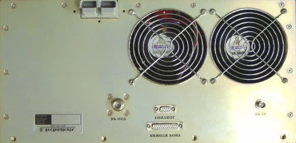
Click to zoom
Application Details
- Equipment Class
- AMP - Amplifier
- Date of Grant
- Sep 08, 2005
- Application Purpose
- Original Equipment
- Date of Application
- Sep 08, 2005
- Equipment Note
- UHF TELEVISION BROADCAST AMPLIFIER
- Frequency Range
- 470.00000000 - 806.00000000
- Company
- Technalogix, Ltd.
- Country
- Canada
Documents & Files
Document Text
Text extracted from the exhibit documents filed with the FCC. Open a document above to read the original.
Users Manual
TAU-500 POWER AMPLIFIER NEW ADVENTURES IN BROADCASTING Technalogix You’ve already unpacked it, haven’t you? You’ve unpacked it and plugged it in and turned it on and fiddled with the knobs. No? Okay, good. Please take a few minutes to read the manual and familiarize yourself with your new Technalogix power amplifier. We believe that this manual, and of course our equipment, should be everything you need to get on the air with superb broadcast quality video. We understand that a capable and confident user will get the most out of our product and we have made every attempt to educate readers of all technical levels. If there is something that is not clear, or you require further information, please do not hesitate to contact us and we’ll be glad to help out. Technalogix Ltd. #4, 8021 Edgar Industrial Place Red Deer, Alberta, Canada T4P 3R3 Phone: 403.347.5400 Fax: 403.347.7444 URL: www.technalogix.ca Email: [email protected] [email protected] We truly appreciate that you have chosen us as your television broadcast system supplier. Happy viewing. Table of Contents SECTION I- SAFEGUARDS...............................................................................................I-1 SAFETY AND FIRST AID.....................................................................................................I-2 OPERATING SAFEGUARDS................................................................................................I-3 SECTION II - WARRANTY..............................................................................................II-1 SECTION III - OVERVIEW..............................................................................................III-1 STANDARD FEATURES....................................................................................................III-1 PRINCIPLE OF OPERATION..............................................................................................III-2 BLOCK DIAGRAM.............................................................................................................III-3 SPECIFICATIONS..............................................................................................................III-5 SECTION IV - RF COMPONENTS................................................................................IV-1 AMPLIFIER PALLETS.......................................................................................................IV-1 SPLITTER/COMBINER.....................................................................................................IV-4 DIRECTIONAL COUPLER.................................................................................................IV-4 ISOLATOR.......................................................................................................................IV-4 FILTER............................................................................................................................IV-4 SECTION V - POWER SUPPLY SECTION......................................................................V-1 SECTION VI - MONITOR AND CONTROL SYSTEM.......................................................VI-1 CONTROL BOARD OVERVIEW (SERIES II-I)...................................................................VI-1 POWER SUPPLY COMPONENTS.....................................................................................VI-1 INTERFACE COMPONENTS.............................................................................................VI-2 SIGNAL CONDITIONING COMPONENTS..........................................................................VI-3 DISPLAY COMPONENTS.................................................................................................VI-4 MICROCONTROLLER COMPONENTS...............................................................................VI-5 FAULT SHUTDOWN.........................................................................................................VI-6 REMOTE PORT...............................................................................................................VI-7 BILL OF MATERIALS.......................................................................................................VI-8 SCHEMATICS................................................................................................................VI-10 SECTION VII - MECHANICAL SECTION......................................................................VII-1 SECTION VIII - INSTALLATION..................................................................................VIII-1 BUILDING RECOMMENDATIONS....................................................................................VIII-1 HEATING AND COOLING REQUIREMENTS....................................................................VIII-2 ELECTRICAL SERVICE RECOMMENDATIONS................................................................VIII-3 ANTENNA AND TOWER RECOMMENDATIONS...............................................................VIII-4 SHELTER SECURITY.....................................................................................................VIII-5 UNPACKING AND INSPECTION......................................................................................VIII-6 LOCATION AND FUNCTION OF CONTROLS AND CONNECTORS (TAU-500 POWER AMPLIFIERS).................................................................................................................VIII-7 LOCATION AND FUNCTION OF CONTROLS AND CONNECTORS (POWER SUPPLY)......VIII-9 INITIAL HOOK UP........................................................................................................VIII-11 SECTION IX - OPERATING PROCEDURE.....................................................................IX-1 SECTION X - MAINTENANCE AND TROUBLESHOOTING...............................................X-1 TROUBLESHOOTING........................................................................................................X-2 I-1 Section I - Safeguards General Safeguards This s…
Text truncated - open the document above for the full version.
Attestation Statements
Technalogix – the company that can! Attestation Statement: TAU-500 Tests were conducted on production models of the equipment on location at Technalogix: #4, 8021 Edgar Industrial Place Red Deer, Alberta Canada T4P 3R3 403.347.5400 ph 403.347.7444 fx All tests were carried out on representative channels in the UHF bands in accordance with FCC Part 73 and Part 74 and Industry Canada BESP-100 and BETS-4. The results in the submitted documentation show that the equipment meets or exceeds the required specifications. Should you have any questions, please do not hesitate to contact Technalogix: Bob Gullon, President and CEO [email protected] Aaron Sivacoe, Engineering Manager [email protected] #4 – 8021 Edgar Ind. Place, Red Deer, AB T4P 3R3 Ph: (403) 347-5400 [email protected] Fax: (403) 347-7444 www.technalogix.ca
Block Diagram
III-3 Block Diagram The RF signal enters through the RF Input connector on the power amplifier enclosure from the modulator or processor. It then passes through an RF attenuator to limit the output power level of the power amplifier and to help buffer any transients that may come into the power amplifier. After attenuation, the signal gets preamplified through the driver pallet before the signal gets split into (2) signals for final amplification. The output of the (2) final amplifier pallets get combined and passes through an isolator and a bandpass filter. Finally, the signal passes through a dual directional coupler for monitoring purposes before heading out to an antenna for broadcast. To Wattmeter and Antenna A=14dB min. A=14dB min. A=+38dB min. A=-0.2dB typical i A=-0.2dB typical A=-0.5dB typical A=-0.05dB typical RF INPUTRF OUT TECH-30U SPLITTER 2-WAY P300-UHF FINAL P300-UHF FINAL 2-WAY COMBINER V V DIRECTIONAL COUPLER V CIRCULATOR ATTENUATION TERMINATION 50 OHM TAU-500 Block Diagram Date: May 24, 2005Page: 1 of 1 RevID
External Photos
Technalogix – the company that can! EXTERNAL CONSTRUCTION Front View: #4 – 8021 Edgar Ind. Place, Red Deer, AB T4P 3R3 Ph: (403) 347-5400 [email protected] Fax: (403) 347-7444 www.technalogix.ca Technalogix – the company that can! Back View:
ID Label/Location Info
Technalogix – the company that can! ID Label: #4 – 8021 Edgar Ind. Place, Red Deer, AB T4P 3R3 Ph: (403) 347-5400 [email protected] Fax: (403) 347-7444 www.technalogix.ca TECHNALOGIX LTD. Made in Red Deer, AB Canada FCC ID:QH5TAU500 I.C. :3803A-TAU500 Model No:TAU-500 Serial No: Actual Size: 2" x 3 1/4" Technalogix – the company that can! ID Label Location: TECHNALOGIX LTD. Made in Red Deer, AB Canada FCC ID:QH5TAU500 I.C. :3803A-TAU500 Model No:TAU-500 Serial No:
Internal Photos
Technalogix – the company that can! TAU-500 CONSTRUCTION POTOGRAPHS Amplifier Pallet Construction: TECH-30U (component side with all components): #4 – 8021 Edgar Ind. Place, Red Deer, AB T4P 3R3 Ph: (403) 347-5400 [email protected] Fax: (403) 347-7444 www.technalogix.ca Technalogix – the company that can! P300-UHF (component side with all components): Technalogix – the company that can! PA Internal Construction
Operational Description
III-2 Principle of Operation The TAU-500 power amplifier supplies a 500-watt peak video signal with an aural carrier level 10 to 13 dB below visual carrier (dBc) on any of the UHF television channels 14 through 69. Please note that channel selection must be made at time of order, as the transmitter or translator is calibrated and tested to the channel requested and is not field tuneable. The TAU-500 power amplifier is a modular solid-state 500-watt broadcast amplifier utilizing readily available RF components wherever possible, thus enhancing the serviceability of the equipment. The TAU-500 is comprised of a TECH-30U driver pallet and (2) P300 final pallets that are combined to create 500 watts of peak visual power in addition to the aural carrier power. The TAU-500 features ultra linear amplification and individual channel RF output bandpass filtering. The amplifier modules are stable for high reliability and long service life. III-3 Block Diagram The RF signal enters through the RF Input connector on the power amplifier enclosure from the modulator or processor. It then passes through an RF attenuator to limit the output power level of the power amplifier and to help buffer any transients that may come into the power amplifier. After attenuation, the signal gets preamplified through the driver pallet before the signal gets split into (2) signals for final amplification. The output of the (2) final amplifier pallets get combined and passes through an isolator and a bandpass filter. Finally, the signal passes through a dual directional coupler for monitoring purposes before heading out to an antenna for broadcast. To Wattmeter and Antenna A=14dB min. A=14dB min. A=+38dB min. A=-0.2dB typical i A=-0.2dB typical A=-0.5dB typical A=-0.05dB typical RF INPUTRF OUT TECH-30U SPLITTER 2-WAY P300-UHF FINAL P300-UHF FINAL 2-WAY COMBINER V V DIRECTIONAL COUPLER V CIRCULATOR ATTENUATION TERMINATION 50 OHM TAU-500 Block Diagram Date: May 24, 2005Page: 1 of 1 RevID III-5 Specifications The following specifications were taken with a Technalogix modulator/processor. Should a different modulator or processor be used, specifications could vary. For this reason, we recommend that any different modulator/processor be shipped to Technalogix so the system can be matched and set up optimally. In addition, the audio/video ratio the input to the power amplifier needs to be –10 dB in order for the software and LCD readout to be accurate. RF Characteristics Frequency range any specified UHF Channel 14 to 60** Frequency Response (one channel) ±0.5 dB Frequency Stability ±250 Hz Selectivity 60 dB (adjacent channel) Minimum Input Level 0 dBmV Rated Visual Output Power 500 Watts Rated Aural Output Power 10% of peak visual power IF Output Level +35 dBmV nominal Input Impedance 75 Ohms Output Impedance 50 Ohms Harmonics > 60 dB below rated power Predominant Intermodulation Distortion dBc = decibels below visual carrier + 920 kHz > -53 dBc - 920 kHz > -53 dBc + 2.66 MHz > -53 dBc - 2.66 MHz > -53 dBc + 5.42 MHz > -53 dBc + 7.16 MHz > -53 dBc 3 rd Order Intermodulation Distortion + 4.5 MHz > -60 dBc + 9.0 MHz > -60 dBc All others > -60 dBc Spurious Emissions > -60 dBc ** Stand-alone power amplifier will operate from channels 14-69. PAL Video Characteristics Input Level to modulator (for 87.5% modulation) 1.0 V PP Differential Phase (at 87.5% modulation) ±2 Degrees Differential Gain (at 87.5% modulation) 2% Group Delay < ±40 nS Video Group Delay Pre-emphasis Conforms to IC/FCC specifications K-Factor 1.9% for 2T Pulse Hum and Noise > 60 dB below rated power III-6 Aural Characteristics Input Level for 25 kHz Deviation 0.3 V PP Frequency Response (Standard Pre-emphasis) ±1 dB Harmonic Distortion (25 kHz Deviation) < 1% 50 Hz to 15 kHz Amplitude Modulation Noise > 50 dB Frequency Modulation Noise > 60 dB Intercarrier Stability ±250 Hz Physical Characteristics Power Requirements Power Supply 230 V AC , 10 A AC Operating Temperature 0 - 50°C Dimensions TAU-500 Power Amplifier W-19" flange (17” encl.), D-25-¼", H-8-¾” (5U) Power Supply W-19" flange (17” encl.), D-2-¼", H-7” (4U) IV-1 Section IV – RF Components Amplifier Pallets The TECH-30U driver pallet consists of (2) separate printed circuit board stages – The first stage is an ultra-linear class-A stage with (3) gain sections providing a typical adjustable power gain of 26dB to 37dB at 10-watts peak. This stage typically draws 2.5 Adc quiescent and a maximum drain current of 5 Adc. The second stage is a linear class AB stage with a typical gain of 13 dB. This stage typically draws 1.0 Adc quiescent and a maximum drain current of 10 Adc. The currents on both stages can be found by measuring the voltage drop across the +30 Vdc input and the I sense connector. The resistance separating these connections is 0.01 ohms, providing a 10 mV per ampere ratio. The P300-UHF pallets used in the final amplification stage use LDMOS (Laterally Diffused Metal Oxide Semiconductor) technology. LDMOS technology offers higher gain, efficiency and linearity over standard MOSFET and Bipolar devices and enhances ruggedness and reliability. LDMOS transistors have the added advantage of not having BEO (Beryllium Oxide) in their construction. The P300-UHF amplifier pallets have a typical gain of 15dB (14dB minimum) and draw no more than 23Adc. Currents for these pallets must be measured with an ammeter in series with the power supply lead. Each of the amplifier pallets is connectorized to optimize servicing and accessibility. All amplifier pallets must have the transistor drain voltages reach at least 26Vdc before the RF drive is applied. IV-2 Splitter/Combiner The splitter and combiner are used to split the RF signal into, and combine the amplified RF signal out of the (2) final amplifier pallets. The connectorized designs are based on the simple isolated Wilkinson combiner design. Due to its electrical and mechanical symmetry, the Wilkinson design’s performance over moderate bandwidths is superior t…
Text truncated - open the document above for the full version.
Parts List/Tune Up Info
Series II - Bill of Materials I 21-Jun-05 ItemQtyComponentsDescriptionTolerancePackageEquivalency 11 BZ101 BUZZER, magnetic, 5V, single toneSMD CT-1205C CUI CT-1205C 22 C101, C105 CAPACITOR, electrolytic, 100uF, 63V<=20%SMT (Panasonic VS "G" size) Panasonic ECE-V1JA101P, NIC NACEW101M63V10x10.5 32 C102, C106 CAPACITOR, electrolytic, 330uF, 35V<=20%SMT (Panasonic VS "G" size) Panasonic ECE-V1VA331P, NIC NACEW331M35V10x10.5 421 C103, C104, C107, C112, C113, C115, C116, C118, C119, C120, C121, C123, C124, C125, C126, C128, C129, C130, C131, C133, C134 CAPACITOR, ceramic, 0.01uF, 63V <=20% SMT 0805 Digikey C0805C103K5RACTU 57 C108, C111, C140, C143, C144, C145, C146CAPACITOR, ceramic, 0.1uF, 25V<=20% SMT 1206Utech GMC31X7R104K50NT 62 C109, C110 CAPACITOR, electrolytic, 100uF, 25V<=20%SMT (Panasonic VS "E" size)Panasonic ECE-V1EA101UP 77 C114, C117, C122, C127, C132, C135, C147CAPACITOR, tantalum, 1uF, 16V<=20% SMT 3216 Sprague 293D105X9035B2T 81 CR101 CLOCK, ceramic resonator, 4.000 MHz, w/caps f <= 0.5% C <= 20% Through hole, 3-position, 0.1" spacing ECS Inc. ZTT-4.00MG 91D101 TV Power Amplifier: DIODE, TVS, 600 watts, Vwm=30V, Vbr min=33.3SMBCrydom SMBJ30A; GI SMBJ30A 101D101 FM Power Amplifier: DIODE, TVS, 600 watts, Vwm=48V, Vbr min=53.3SMBCrydom SMBJ48A; GI SMBJ48A 112 D102,D103 DIODE, schottky, If=3A, Vr=60VSMCInternational Rectifier 30BQ060 121 D104 DIODE, rectifier, If=1A, Vr=200VSMA Diodes Inc S1D-13 132 D108, D109 DIODE, TVS, 600 watts, Vwm=5.0V, Vbr min=6.4 SMBCrydom SMBJ5.0A; GI SMBJ5.0A 141 D110 DIODE, LED, RED, clear or diffusedSMT 1206Lumex SML-LX1206IW 151 F101 FUSE, resettable, Ihold=0.75A, Itrip=1.5A, Vmax=72V 0.23" lead spacing, 20AWG leads Raychem RXE075; Bourns MF-R075 163 F105, F106, F107 FUSE, resettable, Ihold=0.14A, Itrip=0.34A, Vmax=60V miniSMDRaychem miniSMDC014-2 171 J101 CONNECTOR, 4-position plug, 180 degree wire entry, 90 degree screw access, 5.08mm 0.2" spacing Wieland 25.340.3453, Weco 10.808.104 181 J101 CONNECTOR, 4-position header, pluggable, vertical, closed, 5.08mm Through hole, 0.2" spacing Wieland 25.350.3453, Weco 20.806.128 192 J102, J106 CONNECTOR, breakaway header strip, 3- position, 0.1", square post Through hole, 0.1" spacing Molex 22-28-4300; Samtec TSW-130-05-T-S 201 J105 CONNECTOR, breakaway header strip, 2- position, 0.1", square post Through hole, 0.1" spacing Molex 22-28-4300; Samtec TSW-130-05-T-S 213 J102, J105, J106CONNECTOR, 2-position post shunts 0.1" spacing AMP 382811-6; Samtec SNT-100-BK-T 221 J103 CONNECTOR, 5-position plug, 180 degree wire entry, 90 degree screw access, 5.08mm 0.2" spacingWieland 25.340.3553.0 231 J103 CONNECTOR, 5-position header, 0.1", vertical Through hole 0.2" spacing Wieland 25.350.3553.0 242 J107, J108 CONNECTOR, 3-position plug, 180 degree wire entry, 90 degree screw access, 5.08mm 0.2" spacing Wieland 25.340.3353, Weco 10.808.103 252 J107, J108 CONNECTOR, 3-position header, pluggable, vertical, closed, 5.08mm Through hole, 0.2" spacing Wieland 25.350.3353, Weco 20.806.127 261 J109 CONNECTOR, terminal strip, 16-positionThrough hole, 0.1" spacingSamtec TSW-116-18-T-S 271 J109 CONNECTOR, socket strip, 16-positionThrough hole, 0.1" spacingSamtec SSW-116-03-T-S 281 K101 RELAY, DPDT, 5V, 2Adc contact, SMDRelay - Aromat - TX SAAromat TX2SA-5V 291 L101 INDUCTOR, 680uH, Irms=0.4A, DCR=2.02 ohms SMTJW Miller 3316-681M 3010 L102, L105, L106, L107, L108, L109, L110, L111, L112, L113 INDUCTOR, 0.01uH, Imax=0.45A, DCR=0.13 omhs +/- 10%SMT 1210KOA KL32TE010K 311 L103 INDUCTOR, 680uH, Irms=1.3A, DCR=0.2 ohms SMT (Talema S5)Talema SWS-0.85-680 321 LCD101 20 X 4 character liquid crystal display, LED backlit 4-40 pem mount (4)Varitronix 20464K 331 PCB101 Series II, revision H printed circuit board, soldermask, silkscreen, FR4 Alberta Printed Circuits, MPC, GRM, Enigma, ... 342 Q101, Q102 TRANSISTOR, NPN, Ic=1A, Vce=40VSMT SOT-23 Fairchild MMBT2222A; Zetex FMMT2222A; Diodes Inc MMBT2222A-7 351 R101RESISTOR, 4.7 ohm, 1/2 watt, carbon film 5%SMT 2010Panasonic ERJ-12ZYJ4R7U 361 R102 RESISTOR, 15.0 ohm, 1/10 watt, thick film 1%SMD 0805Panasonic ERJ-6ENF15R0V 371 R103 RESISTOR, 75.0 ohm, 1/10 watt, thick film 1%SMD 0805Digikey MCR10EZHF1001, Panasonic ERJ-6ENF75R0V 3811 R104, R105, R106, R109, R110, R111, R112, R115, R116, R132, R134 RESISTOR, 1.00 kohm, 1/10 watt, thick film 1%SMD 0805Panasonic ERJ-6ENF1001V 394 R107, R108, R113, R114 RESISTOR, 10.0 kohm, 1/10 watt, thick film 1%SMD 0805Panasonic ERJ-6ENF1002V revision: date: Optional part depending on power level of TV or FM Series II - Bill of Materials I 21-Jun-05 401 R117 RESISTOR, 4.99 kohm, 1/10 watt, thick film 1%SMD 0805Panasonic ERJ-6ENF4991V 411 R124RESISTOR, 13 kohm, 1/8 watt 1%SMD 0805Rohm MCR10EZHF1302 424 R125, R127, R126, R128RESISTOR, 1 kohm, 1/8 watt 1%SMD 0805Rohm MCR10EZHF1001 431 R129RESISTOR, 121 kohm, 1/8 watt 1%SMD 0805Rohm MCR10EZHF1213 441 R130 RES, 2.15 kohm, 1/10 watt, thick film1%SMD 0805Rohm MCR10EZHF2151 451 R131 RES, 120 ohm, 1/10 watt, thick film1%SMD 0805Panasonic ERJ-6ENF1200V 462U101, U102 TV Power Amplifier: REGULATOR, switching, 5Vdc, 3A, fosc=52kHzSMD TO-263-5National LM2576S-5.0 472U101, U102 FM Power Amplifier: REGULATOR, switching, 5Vdc, 3A, fosc=52kHzSMD TO-263-5National LM2576HVS-5.0 481 U104 REGULATOR, inverter, 100mASMD SOIC-8 National LM2660M; Analog Devices ADM8660, Maxxim MAX660 492 U105, U106OPTOISOLATOR, dual, Viso=5300Vac SMD DIP8Fairchild MCT6S 501 U108OP AMP, quad, low voltage SMD SOIC-14National LMV324M 511 U109 REFERENCE, 2.50V (for TV PA >= 250Wpk) +/-0.2%SMD SOT-23 National LM4040BIM3-2.5 521 U110ADC, 10-bit, 10-channel SMD SOIC-20Analog Devices AD7812YR 532 U111, U112LOGIC, 8-bit shift register with latches SMD SOIC-16 Fairchild MM74HC595M; On Semi MC74HC595AD; Phillips 74HC595D 541 U113 SUPERVISOR, n-channel, open drain, internal pullup resistor SMD SOT-23 MCP130T-450I 551 U114 MICROCONTROLLER, OTP, 4k, 22 I/O lines Through hole DIP-28 Microchip PIC16C63A-04/SP 561 J111 Connector, socket, 28-position, DIP, 0.3" spacing Th…
Text truncated - open the document above for the full version.
Parts List/Tune Up Info
Technalogix – the company that can! August 22, 2005 To Whom it May Concern, This letter certifies that there is no internal tuning that needs to be completed in the Technalogix line of power amplifiers. Should require any further information, do not hesitate to contact us: Aaron Sivacoe Engineering Manager [email protected] Bob Gullon President and CEO [email protected] Best regards, Aaron Sivacoe #4 – 8021 Edgar Ind. Place, Red Deer, AB T4P 3R3 Ph: (403) 347-5400 [email protected] Fax: (403) 347-7444 www.technalogix.ca
RF Exposure Info
Technalogix – the company that can! RF EXPOSURE STATEMENT A Narda 8616 radiation Meter with suitable probes was used and there was NO measurable radiation even at a distance of 0.5 meters from the transmitter cabinet #4 – 8021 Edgar Ind. Place, Red Deer, AB T4P 3R3 Ph: (403) 347-5400 [email protected] Fax: (403) 347-7444 www.technalogix.ca
Schematics
P300-UHF-16 Schematic BK LT CTRL SELECT 1 SERIES II, REV. I - Control System +5Vdc C107 Vin Cond C104C103 L102 VR101 + C109 + C110 P1 P2 P3 P4P5 P6 P7 P8 U104 BkLtCtrl GND Vcoupler GND Vin L101 D102 + C101 D101 F101 3 J101 1 Vin 2 Vout 4 Feedbk 3 Gnd 5 On/Off U101 + C102 +5Vdc 4 J101 + C105 + C106 2 Vin 1 Vout 4 Feedbk 3 Gnd 5 On/Off U102 D103 L103 Pin15LCD IN COM OUT U103 C108 1 J101 J101 2 +5Vdc Pin3LCD J102 R103 R102 R101 A. Sivacoe SERIES II: Control System IPower Supply Section Date: March 28, 2005Page: 1 of 1 RevID Buzzer delete 2 SERIES II, REV. I - Control System D104 J1043 J1045 SEL In J1044 J1042 NAV In J1041 +5Vdc J106 J1035 Ground J1033 J1034 J1032 +5Vdc +5Vdc R104 R117 J107 2 Q102Rly.Ctrl +5Vdc K101 Rly. COM Rly. N/O Rly. N/C J107 3 J107 1 Buzzer J105 Q101 +5Vdc R116 RES In NC(RC6) VW In PWR In J1031 P1 P2 P3 P4P5 P6 P7 P8 U106 P1 P2 P3 P4P5 P6 P7 P8 U105 R105R106 R109 +5Vdc R107R108 VW uPC PWR uPC R115 R110R111R112 +5Vdc R113R114 PIN17uPC RES uPC BZ101 A. Sivacoe SERIES II: Control System IInterface Section Date: March 21, 2005Page: 1 of 1 RevID 3 For U7 PSU FWD RFL Low Threshold Adjust SERIES II, REV. I - Control System J108 4 Analog 4 VR105 VR104 VR103 C121 L108 C120 Vin Cond + C117 + C114 C119C118 L107 L106 C116C115 VR102 5 6 4 11 7 + U108 2/4 3 2 4 11 1 + U108 1/4 10 9 4 11 8 + U108 3/4 12 13 4 11 14 + U108 4/4 J108 1 Analog 1 J1082 Analog 2 J1083 Analog 3 Isoltd 4 Isoltd 3 Isoltd 2 Isoltd 1 C112 F107 F106 F105 D108 D109 C113 +5V L105 D107 D106 F103 F104 C111 Isoltd 6 Isoltd 7 Isoltd 8 12 13 4 11 14 + U107 4/4 J108 8 Analog 8 D105 F102 Analog 7 J108 7 Analog 6 J108 6 Analog 5 J108 5 9 10 4 11 8 + U107 3/4 3 2 4 11 1 + U107 1/4 R124 R130 R129 R128 R127 R126 R125 R119 R118 R120 R121 R122 R123 A. Sivacoe Series II: Control System IAnalog Input Section Date: March 21, 2005Page: 1 of 1 RevID Pin 3 on U109 is left unconnected on PCB 4 FWD PSU RFL Low Thresh SERIES II, REV. I - Control System C133 L113 C130 L112 C125 L110 C123 L109 C129C128 L111 2 1 U109 +5Vdc For U110 C140 + C142C141 + C139C138 + C137C136 + C135C134 + C132C131 + C127C126 C124 + C122 DtoUPC DfromUPC Dclk ConvStrt Isoltd 1 Isoltd 2 Isoltd 3 Isoltd 4 Isoltd 6 Isoltd 7 Isoltd 8 Vref Cref Vin1 AGND Vin2 Vin3 Vin4 Vin5 Vin6 Vin7 Vin8 A0 DGND TFS RFS Dout Din Dclk ConvStart Vdd U110 R131 A. Sivacoe Series II: Control System IAnalog Conversion Section Date: March 21, 2005Page: 1 of 1 RevID SERIES II, REV. I - Control System 5 U11: LCD control signals, LCD backlight control, and External interface outputs U12: LCD data bus (D0...D7) D0...D7 is text or instruction Pin3LCD uPCPIN14Q103 1 Ext. PSU serial_outresetshift_clklatch_clkoutput_enserial_inQa(out_1)Vcc Qb(out_2)Qc(out_3)Qd(out_4)Qe(out_5)Qf(out_6)Qg(out_7) Qh(out_7) GND U112 Latch2CS Latch1CS +5Vdc C143 BkLtCtrl Pin15LCD 234 Unbuf A Unbuf B Unbuf C Unbuf D 1615 LED A LED K 32 J109 1 LCD Vo LCD Vdd LCD Vss 65478910111213 LCD RS LCD R/*WLCD E LCD D6 LCD D5 LCD D4 LCD D3 LCD D2 LCD D1 LCD D0 LCD D7 Dclk DfromUPC 14 J110 5 serial_outresetshift_clklatch_clkoutput_enserial_inQa(out_1)Vcc Qb(out_2)Qc(out_3)Qd(out_4)Qe(out_5)Qf(out_6)Qg(out_7) Qh(out_7) GND U111 R133 R132 A. Sivacoe Series II: Control System ILCD Section Date: March 2, 2005Page: 1 of 1 RevID SERIES II, REV. I - Control System 6 + C147 C144 D110 Dclk DtoUPC Dig.In 3 Dig.In 2 Dig.In 1 C146 Buzzer Latch2CS Latch1CS DfromUPC Rly.Ctrl Reset Dig.Out2 CONVST Dig.Out1 Vcc C145 +5Vdc MCLR/Vpp RA0 RA1 RA2 RA3 RA4 RA5 Vss OSC1/CLKin OSC2/CLKout RC0/T1CKI RC1/CCP2 RC2/CCP1 RC3/SCK/CLRC4/SDI/SDA RC5/SD0 RC6/TX/CK RC7/RX/CK Vss Vdd RB0/INT RB1 RB2 RB3 RB4 RB5 RB6 RB7 U114 *CS SO *WP VssSI SCK *HOLD Vcc U115 Vcc GND Reset U113 OSC1 OSC2 GND CR101 R134 A. Sivacoe Series II: Control System IMicrocontroller Section Date: March 2, 2005Page: 1 of 1 RevID + - STAR POINT GND 1 1 2 2 3 4 3 1 brown green grey red 22AWG yellow orange purple green green green brown purple red 18AWG red 22AWG blue green - Vin Ground +8Vdc FWD in RFL in Pallet Disable Reset View Input On/Off Input Ground to Switches Fault Input Ground (unused) J1 2 J1 1 J1 3 J1 4 J6 2 J3 2 J7 7 J7 6 J3 3 J3 1 J3 5 J3 4 Control PCB Series IIG ON/OFF VIEW RESET PSU GND OnOff RESET DB25 Remote Port GND FAULT ONOFF CTRL DB9 RFLFWD 8V GND Coupler Directional V V DC Supply DB9 Pallet Driver Series II Control System Wiring I Date: June 29, 2005Page: 1 of 1 RevID
Test Report
TAU-500 TEST REPORT S/N: 06200399 Prepared by: Aaron Sivacoe Date: August 15, 2005 2 Contents Contents____________________________________________________________________2 Test Equipment______________________________________________________________3 Performance Specifications____________________________________________________4 Visual Power Output Rating___________________________________________________4 Visual Power Adjustment Capability____________________________________________6 Aural Power Output Rating___________________________________________________7 Carrier Frequency Tolerance__________________________________________________9 Visual Frequency Response__________________________________________________12 Intermodulation Distortion___________________________________________________15 Spurious Emissions_________________________________________________________17 Modulation_______________________________________________________________19 K Pulse to Bar (Kpb) Rating__________________________________________________20 2T Pulse K (K2T) Rating____________________________________________________21 Chrominance-Luminance Gain Inequality_______________________________________22 Chrominance-Luminance Delay Inequality______________________________________23 Differential Gain Distortion__________________________________________________24 Differential Phase Distortion_________________________________________________25 Group Delay Response______________________________________________________26 Horizontal Timing__________________________________________________________27 Audio Amplitude Frequency Response_________________________________________28 3 Test Equipment Equipment Manufacturer Model Number Serial Number Test Signal Generator Tektronix TSG95 B025497 Test Signal Generator Tektronix 1910 B022706 Spectrum Analyzer Advantest R3162 110301419 Spectrum Analyzer Tektronix 2710 B021677 Waveform Analyzer/Monitor Tektronix VM700A B020283 Radiation Meter Narda Network Analyzer Agilent 8753ET US39170436 Frequency Counter HP 5343A 2428A01747 Audio Generator HP 209A 1045A06481 Noise and Distortion Meter HP 334A 1551U00970 Coaxial Attenuator (30 dB) Bird 8329-310 258 Coaxial Attenuator (30 dB) Bird 8323 2221 Coaxial Attenuator (6 dB) Weinschel 58-6-43 RF Wattmeter Bird 4304A 0811 RF Wattmeter Coaxial Dynamics 81060A 1034 RF Load (1200 W) Microwave Devices 611.11 RF Load (600W) Bird 8402 1595 Directional Coupler HP 778D Variable Autotransformer Staco Energy Products 3PN1010 122-0003 8645 True RMS clamp on meter Tenma 72-6131 96082691 Digital Multi-meter Hung Chang HC-5010EC 15003374 Oscilloscope (150 MHz) Tektronix 2445 B021074 Television Demodulator Rhode and Schwarz EFA83 832495/006 Tunable Down Converter Tektronix TDC-10 BO10435 Television Demodulator MSI MSI-320 D-022 Digital Camera Sony DSC-P73 7412902 4 Performance Specifications Visual Power Output Rating Definition: The visual power output rating of the television transmitting equipment shall be the peak envelope power. This is also the average power measured during a synchronizing pulse. Requirement: Specified by the manufacturer as 500 watts peak. Method: The visual carrier is modulated with a sync and blanking signal. The aural carrier is not present. An average reading RF wattmeter is placed between the transmitter output (directly on the directional coupler’s N connector on the back panel) and the 50 O dummy load. The peak visual power is the measured average power multiplied by a factor of 1.68. Due to the low level of the RF Output signal, a spectrum analyzer was used to measure the visual output rating. Measurement: The rated visual output power is 500 watts peak. 5 6 Visual Power Adjustment Capability Definition: The peak output power adjustment ca…
Text truncated - open the document above for the full version.
Contact Information
Applicant
Robert Gullon(President)
Technical Specifications
| # | Rule Parts | Frequency Range | Power Output | Emission | Tolerance |
|---|---|---|---|---|---|
| 2 | 74 | 470 MHz - 806 MHz | 50 W | F3E | Amp |
Other Applications from Technalogix, Ltd.
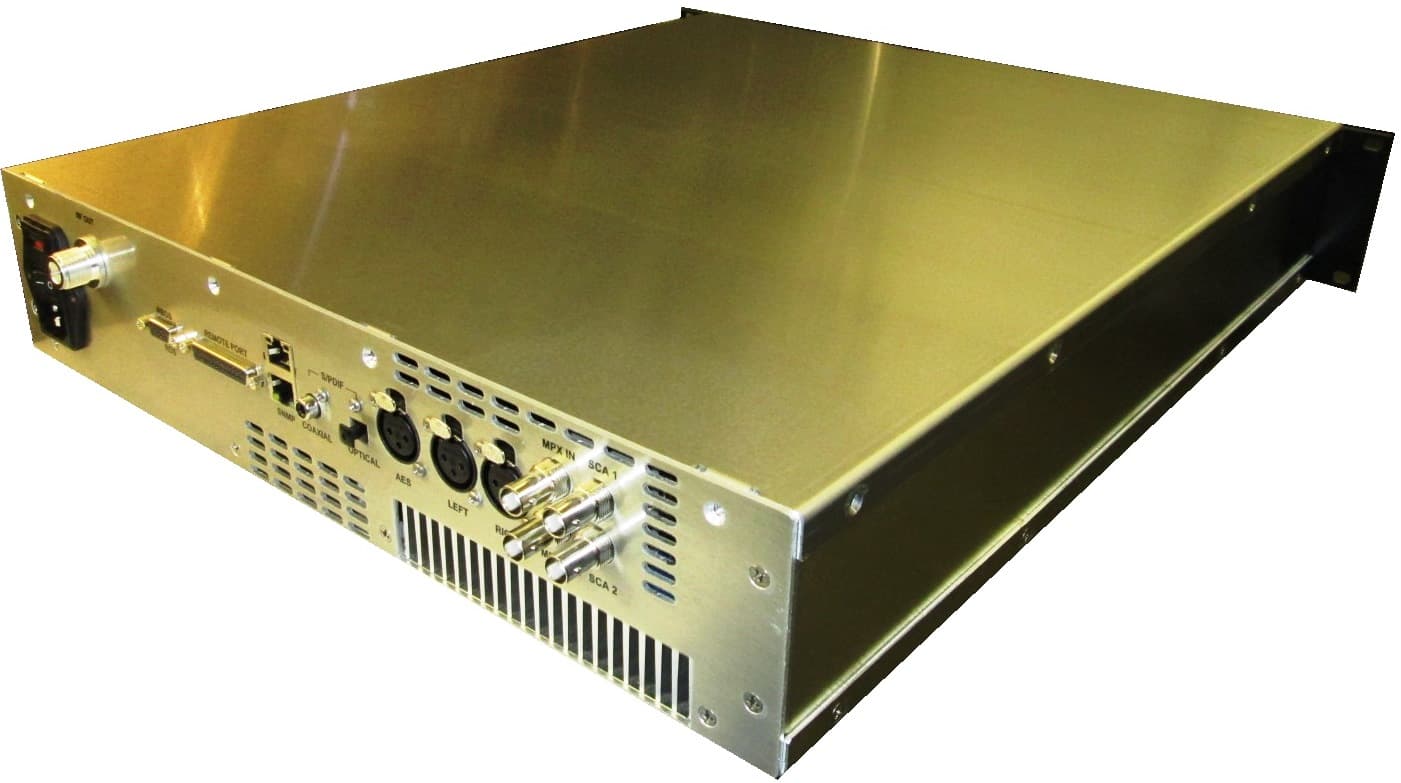
QH5TXF500
Dec 16, 2014FM Broadcast Transmitter, 500-Watts
Equipment Class
TBC - Licensed Broadcast Station Transmitter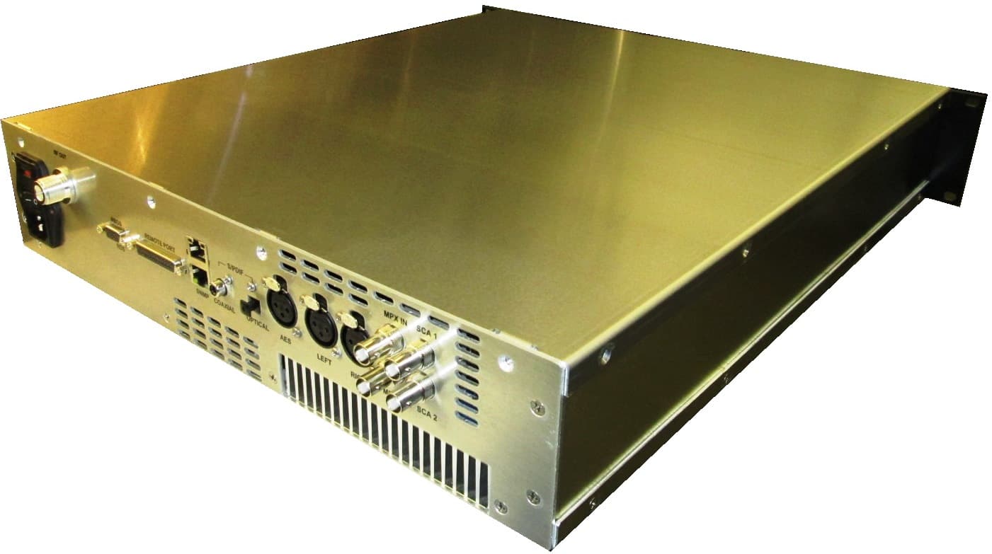
QH5TXF50
Oct 02, 2014FM Broadcast Transmitter, 50 Watts
Equipment Class
TBC - Licensed Broadcast Station Transmitter
QH5TXF1000
Jun 11, 2014FM Broadcast Transmitter, 1000-Watts
Equipment Class
TBC - Licensed Broadcast Station Transmitter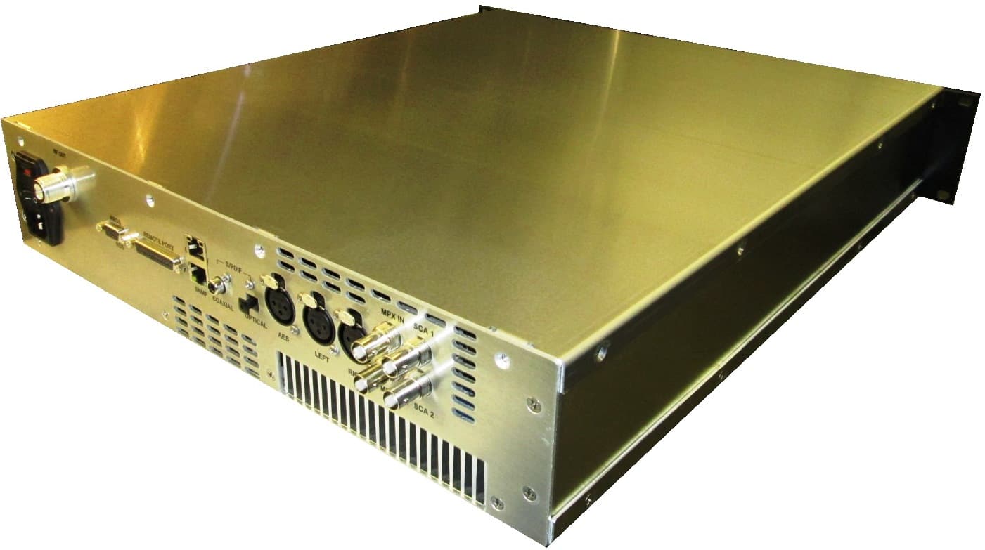
QH5TXF300
May 08, 2014FM Broadcast Transmitter, 300 Watts
Equipment Class
TBC - Licensed Broadcast Station Transmitter
QH5TXUD1000
May 24, 20111000 W Digital TV Transmitter
Equipment Class
TBC - Licensed Broadcast Station Transmitter