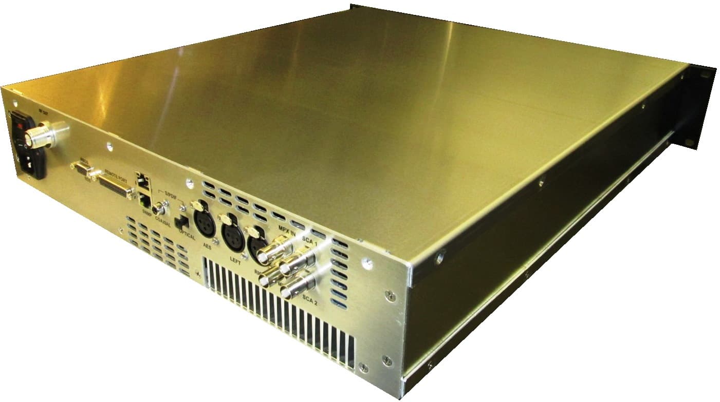
QH5TXUD10001000 W Digital TV Transmitter
Technalogix, Ltd.
Click to zoom
Application Details
- Equipment Class
- TBC - Licensed Broadcast Station Transmitter
- Date of Grant
- May 24, 2011
- Application Purpose
- Original Equipment
- Date of Application
- May 24, 2011
- Equipment Note
- 1000 W Digital TV Transmitter
- Frequency Range
- 614.00000000 - 806.00000000
- Company
- Technalogix, Ltd.
- Country
- Canada
Documents & Files
Document Text
Text extracted from the exhibit documents filed with the FCC. Open a document above to read the original.
Users Manual
TAUD-1000 BROADCAST TRANSMITTER OPERATING MANUAL You’ve already unpacked it, haven’t you? You’ve unpacked it and plugged it in and turned it on and fiddled with the knobs. No? Okay, good. Please take a few minutes to read the manual and familiarize yourself with your new Technalogix power amplifier. We believe that this manual, and of course our equipment, should be everything you need to get on the air with superb broadcast quality video. We understand that a capable and confident user will get the most out of our product and we have made every attempt to educate readers of all technical levels. If there is something that is not clear, or you require further information, please do not hesitate to contact us and we’ll be glad to help out. Technalogix Ltd. #4, 8021 Edgar Industrial Place Red Deer, Alberta, Canada T4P 3R3 Phone: 403.347.5400 Fax: 403.347.7444 URL: www.technalogix.ca Email: [email protected] [email protected] We truly appreciate that you have chosen us as your television broadcast system supplier. Happy viewing. I-1 Technalogix Ltd Section I - Safeguards General Safeguards This section is written as a general guide to keep all 5 fingers on your hand and is intended for those having previous knowledge and experience with these kinds of equipment. It is not intended to contain a complete statement of all safety precautions, which should be observed by personnel using this or other electronic equipment. DOCUMENTATION - Read, retain and follow instructions before operating the equipment. There is a lot of useful information in the manual, and besides, we spent a lot of time writing it! ENVIRONMENT - To reduce the risk of fire or electric shock, do not expose this equipment to rain, moisture, or rye and sodas at the company Christmas party. Refer all servicing to qualified service personnel. SERVICING - Do not attempt to service this equipment yourself as opening or removing covers can result in a warm tingly feeling and will void the warranty. Refer all servicing to qualified service personnel. I-2 Technalogix Ltd Safety and First Aid Personnel engaged in the installation, operation, maintenance, or servicing of electronic equipment are exposed to the hazard of high voltage. It is imperative that all safety regulations and precautions are consistently observed. Knowledge of first aid procedures is recommended. The following information is presented as a reference only. • At all times, avoid placing any part of the body in series between ground and circuit points, whether power is on or off. • Dangerous voltage may be present in equipment even though power is off. Do not open the cabinet. Refer servicing to qualified service personnel. • It is the duty of all personnel to be prepared to give adequate emergency first aid treatment and thereby prevent avoidable loss of life. • There are three principle degrees of burns, recognizable as follows: • a first-degree burn reddens the skin. • a second-degree burn blisters the skin. • a third degree burn chars the flesh and frequently places the victim in a state of shock accompanied by respiratory paralysis. • Respiratory paralysis can cause death by suffocation within seconds. It is imperative that the approved methods of artificial respiration are initiated immediately and continue until the victim’s breathing is normal. • A muscular spasm of unconsciousness may render the victim unable to break free of the electric power. If this is the case, turn the power off immediately. DO NOT TOUCH THE VICTIM OR YOU MAY SHARE THE SAME PREDICAMENT. • If the power cannot be turned off immediately, very carefully loop a dry rope, article of clothing, length of strong cloth or a rolled-up newspaper around the victim and pull the victim free of the power source. Carefully avoid touching the victim or clothing. • Once free of the power source, the victim must be placed in a reclining position and covered with a blanket or newspapers to keep warm. At the first opportunity, enlist help in summoning a doctor. If a doctor cannot be summoned, transport the victim to the doctor or a hospital. Be sure the victim is kept well covered and warm while awaiting professional treatment. I-3 Technalogix Ltd Operating Safeguards It is a known fact that our broadcast transmitters and translators enjoy 50-ohm load impedances. So much so, that it is imperative you maintain 50-ohm impedances throughout your system. In return, your equipment will provide you with maximum power transfer to the antenna and decreased reflected power heading back towards the amplifier pallets, reducing the amount of magic smoke that gets let out of the power amplifier. Before anything is turned on, ensure that there is a 50-ohm path from the output of each stage to the input of the next, all the way to the antenna. In addition to maintaining proper 50-ohm impedances throughout the signal chain, it is also important, whenever possible, to make sure the RF drive going to the input of the power amplifier is removed before turning on or turning off the DC power supply. This is because all of the RF transistors used in the individual amplifier pallets are fabricated with LDMOS (Laterally Diffused Metal Oxide Semiconductor) technology. Nice and linear yes, but they do not like to make any RF power when their supply voltages are not within a specific range. When you first turn your power amplifier on or off, the DC power supply’s output voltage may take a while to stable out to a safe operating voltage. Ten seconds wait before applying the RF drive will ensure no issues arise. Our power amplifiers are designed to reliably generate a specific RF output power. Failing to adhere to overdriven amplifier warnings can decrease the reliability of your system, and frankly, makes our repair department busy and grumpy. If you need to transmit to a little larger coverage, you are better off increasing antenna gain, and more importantly, antenna height above average terrain. On TV and FM broadcast freq…
Text truncated - open the document above for the full version.
Attestation Statements
Technalogix – the company that can! Ph: (403) 347-5400 [email protected] Fax: (403) 347-7444 www.technalogix.ca #4 –8021 Edgar Ind. Place, Red Deer, AB T4P 3R3 April 14, 2011 Attestation Statement: TXUD-1000 Tests were conducted on production models of the equipment on location at Technalogix: #4, 8021 Edgar Industrial Place Red Deer, Alberta Canada T4P 3R3 403.347.5400 ph 403.347.7444 fx All tests were carried out in accordance with FCC Part 2, Part 73.682(d), and Part 74. The results in the submitted documentation show that the equipment meets or exceeds the required specifications. Should you have any questions, please do not hesitate to contact Technalogix: Bob Gullon, President and CEO [email protected] Aaron Sivacoe, Technical Director [email protected]
Cover Letter(s)
April 27, 2011 To: Federal Communications Commission Authorization and Evaluation Division Confidentiality Request regarding application for certification of FCC ID: QH5TXUD1000 Pursuant to Sections 0.457 and 0.459 of the Commission’s Rules, we hereby request confidential treatment of information accompanying this application as outlined below: Block Diagram Schematic Diagram Circuit Description Parts List Tune Up Procedure The above materials contain trade secrets and proprietary information not customarily released to the public. The public disclosure of these materials may be harmful to the applicant and provide unjustified benefits to its competitors. The applicant understands that pursuant to Section 0.457 of the Rules, disclosure of this application and all accompanying documentation will not be made before the date of the Grant for this application. Pursuant to DA04‐1705 June 15, 2004 of the Commission’s public notice, we also request available maximum days of temporary confidential treatment of information accompanying this application as outlined below: External Photos Internal Photos User’s Manual Test Setup Photos if applicable Bob Gullon, President and CEO [email protected] #4 –8021 Edgar Ind. Place, Red Deer, AB T4P 3R3 Ph: (403) 347‐5400 [email protected]
Cover Letter(s)
April 14, 2011 This report is in support of an application by Technalogix Ltd. for certification of transmitting equipment used for UHF digital television systems. Specifically, Technalogix is requesting certification of the Technalogix TXUD-1000 ATSC compliant digital television transmitter. The TXUD-1000 supplies a 1000 watts ATSC television signal on any of the UHF television channels. The emission designators based on FCC Part 73.682(d) transmitters are 6M00K1D. Should you have any questions, please do not hesitate to contact Technalogix: Bob Gullon, President and CEO [email protected] Aaron Sivacoe, Technical Director [email protected] Ph: (403) 347-5400 [email protected] Fax: (403) 347-7444 www.technalogix.ca #4 –8021 Edgar Ind. Place, Red Deer, AB T4P 3R3 Technalogix – the company that can!
External Photos
Technalogix – the company that can! Ph: (403) 347-5400 [email protected] Fax: (403) 347-7444 www.technalogix.ca #4 –8021 Edgar Ind. Place, Red Deer, AB T4P 3R3 April 14, 2011 EXTERNAL CONSTRUCTION Modulator: Front View Back View Top View (front side down) Bottom View (front side down) Right Side View Left Side View Technalogix – the company that can! Front (bird’s-eye view) Back (bird’s-eye view) Technalogix – the company that can! Power Amplifier: Front View Back View Technalogix – the company that can! Top View Bottom View Technalogix – the company that can! Right Side View Left Side View Technalogix – the company that can! Front (bird’s-eye view) Back (bird’s-eye view) Technalogix – the company that can! Filter/Combiner: Front View Back View Technalogix – the company that can! Right Side View Left Side View Technalogix – the company that can! Front (bird’s-eye view) Back (bird’s-eye view) Technalogix – the company that can! Power Supply: Front Back Left Right Technalogix – the company that can! Top Bottom Technalogix – the company that can! Front (Bird’s eye view) Back (Bird’s eye view) Technalogix – the company that can!
ID Label/Location Info
Technalogix – the company that can! Ph: (403) 347-5400 [email protected] Fax: (403) 347-7444 www.technalogix.ca #4 –8021 Edgar Ind. Place, Red Deer, AB T4P 3R3 April 14, 2011 ID Label: TECHNALOGIX LTD. Made in Red Deer, AB Canada FCC ID:QH5TXUD1000 I.C. :t.b.d. Model No:TXUD-1000 Serial No: Actual Size: 2" x 3 1/4" ID Label Location: Technalogix – the company that can! TECHNALOGIX LTD. Made in Red Deer, AB Canada FCC ID:QH5TXUD1000 I.C. :t.b.d. Model No:TXUD-1000 Serial No:
Internal Photos
Technalogix – the company that can! Ph: (403) 347-5400 [email protected] Fax: (403) 347-7444 www.technalogix.ca #4 –8021 Edgar Ind. Place, Red Deer, AB T4P 3R3 CONSTRUCTION POTOGRAPHS Amplifier Pallet Construction: UHFTV-50 driver : UHFTV-200 final : Modulator : Technalogix – the company that can! Power Amplifiers (lids installed): Technalogix – the company that can! Power Amplifiers (lids removed): Technalogix – the company that can! Filter/Combiner: Technalogix – the company that can! Power Supply: Technalogix – the company that can!
Test Report
TXUD-1000 TEST REPORT Prepared by: Mohammad Kashi , Test Technician Reviewed by: Aaron Sivacoe, P.ENG Date: Apr 14, 2011 2 Contents Contents ..............................................................................................................2 Test Equipments .................................................................................................3 Block Diagram.....................................................................................................4 Performance Specifications...............................................................................5 POWER OUTPUT MEASUREMENT ................................................................5 FREQUENCY OFFSET.....................................................................................9 FREQUENCY STABILITY ...............................................................................10 OUT-OF-BAND EMISSION......................................................................................................11 RADIO NAVIGATION SATELLITE SERVICES PROTECTION...............................26 CABINET RADIATION ....................................................................................31 Photos................................................................................................................34 3 Test Equipments Equipment Manufacturer Model Number Serial Number Spectrum Analyzer Advantest R3162 110301419 TV Test Receiver Rohde & Schwarz EFA-53 100209 Network Analyzer Agilent 8753ET US39170436 Digital Power Meter Bird 5000-EX 4593 Power Sensor Bird 5011 0746 Clamp on meter Extech Instruments MA220 05144301 Antenna Aaronia Hyperlog 4060 04275 RF Load (600W) Bird 8402 1595 RF Signal Sampler Bird 4275 - RF Signal Sampler Coaxial Dynamics 7992 - High Pass Filter Mini-Circuits NHP-900+ V8718600825 High Pass Filter Mini-Circuits VHF-2700A+ 30823 Attenuator Mini-Circuits HAT-10 - 4 Test Setup Block Diagram Digital Source Modulator Power Amplifier RF Tap-Off 50 Ohm Load Spectrum Analyzer EFA Test Receiver Power Meter Digital Receiver 5 Performance Specifications OUTPUT POWER MEASUREMENT ATSC Standard A/64, Rev. A Section 4.1.5 - The lower allowed power value should be 95% of authorized power and the upper allowed value should be 105% of authorized power. Procedure: Power was measured using a precision Digital Power Meter through a directional coupler. The Power Meter was calibrated to take into account the loss of the cable used and the coupling factor. Measurement: Rated Output Power = 1000 Watts Exhibit of Output Power: Power Meter 95% 100% 105% Measured Power 950 Watts 1000 Watts 1050 Watts 6 Total Loss (40MHz span) Output Cables+Attenuation+Signal Sampler Total Loss (Wide span) Output Cables+Attenuation+Signal Sampler 7 Signal Sampler Coupling Factor 30dB Attenuation 8 Calculations: For the Output Power a) Total loss including: output cable, 30dB Attenuation and signal sampler = 53.090 dB. b) Measured Output Power = 4.904 mW. 1. Total Loss of the transmission line = Output Cable Loss + Attenuation +Signal Sampler Coupling Factor Total Loss = 53.090 dB 2. Total Loss = 10 log (Power actual /Power measured ) 53.090 dB = 10 log (Power actual /0.004904W) Inv log 5.3090 = Power actual /0.004904W 203704.20 (0.004904W) = Power actual Power actual = Output Power = 998.96W 9 FREQUENCY OFFSET ATSC Standard A/64, Rev. A Section 4.1.6 - The 8-VSB pilot should be 309.441 kHz (± 1 kHz) above the lower edge of the channel assigned to the DTV transmitter. Procedure: The pilot frequency was measured by taking a sample from a directional coupler to a TV Analyzer. The offset in the pilot frequency was displayed on the Analyzer screen automatically. Measurement: Pilot Frequency (Ideal) = 536.3094406 MHz Pilot Frequency (Actual) = 536.3094540 MHz Pilot Frequency Offset = +13.4 Hz Exhibit of Pilot Frequency Offset: 10 FREQUENCY STABILITY ATSC Standard A/64, Rev. A Section 4.1.6 / FCC 47CFR§2.1055 - The output frequency must not exceed +/- 10 KHz from the designated frequency for the pilot. Procedure: The pilot frequency was measured by taking a sample from a directional coupler to a TV Analyzer. Using a “Variac”, the pilot frequency was measured at 85%, 100%, and 115% of the nominal line. In addition, the temperature was varied from 0°C to 50°C and the pilot frequency was measured at 10 degree increments. Measurement: Modulator Line Voltage Volts (V) Percentage (%) Measured Pilot Frequency (MHz) 104 85 536.3095345 120 (nominal) 100 536.3094540 140 115 536.3095986 Temperature (°C) P.A. Measured Pilot Frequency (MHz) 0 536.3094393 10 536.3094411 20 536.3094540 30 536.3094555 40 536.3094997 50 536.3095435 Summary: Reference pilot frequency (20°C, 120VAC) : 536.3094540 MHz Pilot Frequency Deviation with respect to Line Voltage Range: 64.1 Hz Pilot Frequency Deviation with respect to Temperature Range: 104.2 Hz 11 OUT-OF-BAND EMISSION SIMPLE MASK FCC 47CFR§74.794(a)(2)(i) a) In the range between ½ the width of the Resolution Bandwidth filter used and 500 KHz from the Band Edge: Emissions ≤ -46 dB b) More than 6 MHz from the Band Edge: Emissions ≤ -71 dB c) At any frequency between 500 KHz and 6 MHz from the Band Edge: Emissions ≤ -[46+(|∆F| 2 /1.44)] dB where: ∆F is the frequency difference, in MHz, from the edge of the transmitter’s Frequency Band Procedure: a) The emission at 500 KHz from the band edge was measured by taking a sample from a directional coupler to a TV Analyzer. The upper and lower shoulder attenuation was displayed on the Analyzer screen automatically. b) The harmonic emissions were measured using the spectrum analyzer’s channel power measurement capabilities. The difference between the total average power of the 6 MHz band and the channel power of each of the harmonics up to 8 GHz (spectrum analyzer’s limitation) including all the corrections* determines if the emissions are within the limits of the 8-VSB Mask. The same measurement applied to spurious emissions but only those of visible amplitude w…
Text truncated - open the document above for the full version.
Test Setup Photos
34 Photos General Test Setup 35 Cabinet Radiation Test Setup
Contact Information
Applicant
Robert Gullon(President)
Technical Specifications
| # | Rule Parts | Frequency Range | Power Output | Emission | Tolerance |
|---|---|---|---|---|---|
| 2 | 74 | 614 MHz - 806 MHz | 1000 W | 6M00K1D | 1000 Hz |
Other Applications from Technalogix, Ltd.
QH5TXF500
Dec 16, 2014FM Broadcast Transmitter, 500-Watts
Equipment Class
TBC - Licensed Broadcast Station Transmitter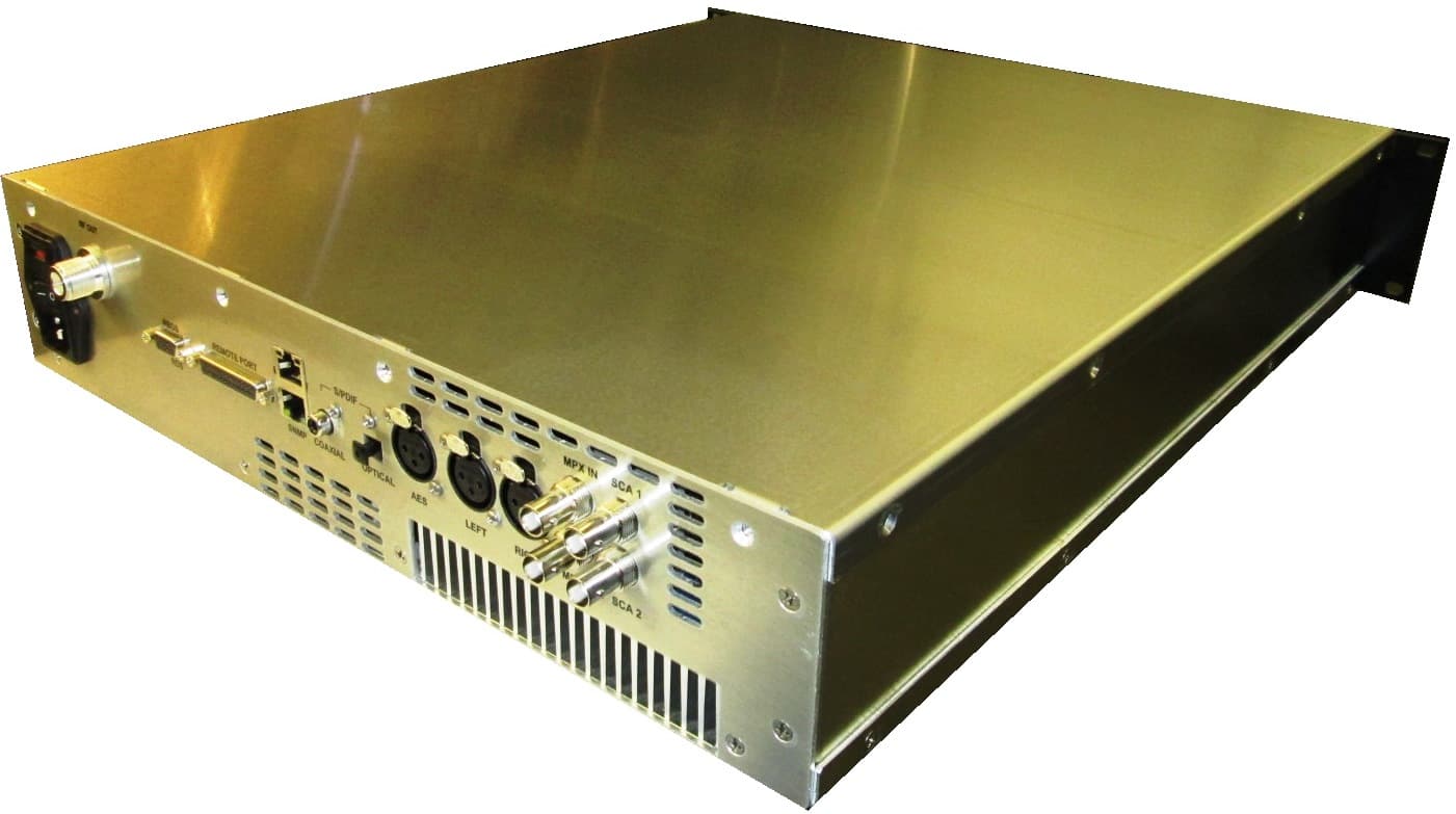
QH5TXF50
Oct 02, 2014FM Broadcast Transmitter, 50 Watts
Equipment Class
TBC - Licensed Broadcast Station Transmitter
QH5TXF1000
Jun 11, 2014FM Broadcast Transmitter, 1000-Watts
Equipment Class
TBC - Licensed Broadcast Station Transmitter
QH5TXF300
May 08, 2014FM Broadcast Transmitter, 300 Watts
Equipment Class
TBC - Licensed Broadcast Station Transmitter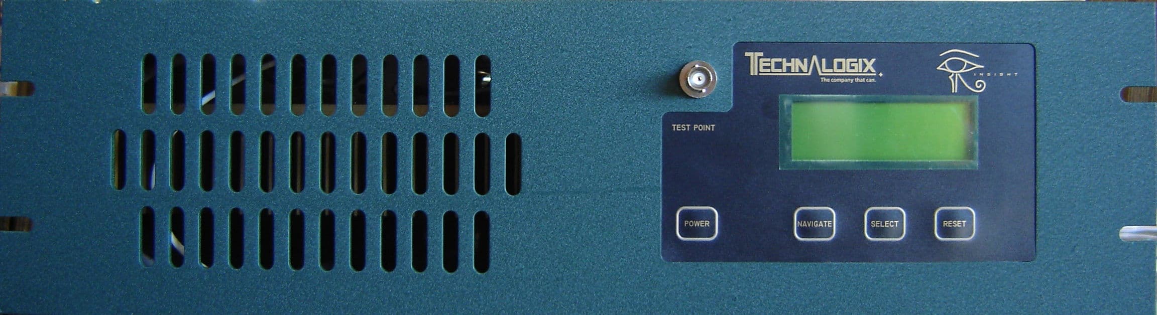
QH5TAV25H
Jul 29, 2007VHF Television Broadcast Transmitter
Equipment Class
AMP - Amplifier