QH5TXV1000TXV-1000 VHF Transmitter
Technalogix, Ltd.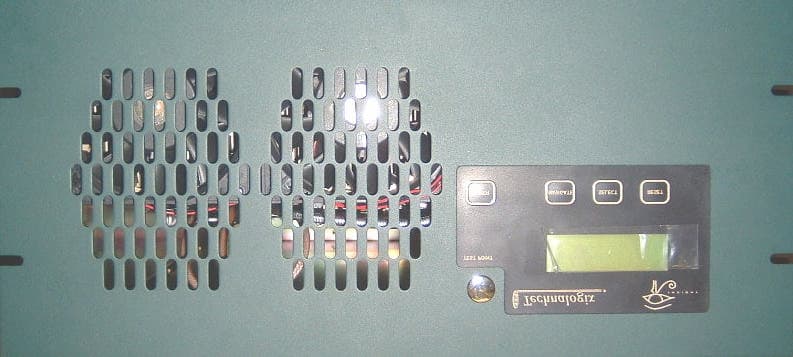
Click to zoom
Application Details
- Equipment Class
- TBC - Licensed Broadcast Station Transmitter
- Date of Grant
- Nov 30, 2004
- Application Purpose
- Original Equipment
- Date of Application
- Aug 29, 2004
- Equipment Note
- TXV-1000 VHF Transmitter
- Frequency Range
- 170.00000000 - 230.00000000
- Company
- Technalogix, Ltd.
- Country
- Canada
Documents & Files
Document Text
Text extracted from the exhibit documents filed with the FCC. Open a document above to read the original.
Users Manual
TAV-1000 POWER AMPLIFIER NEW ADVENTURES IN BROADCASTING Technalogix You’ve already unpacked it, haven’t you? You’ve unpacked it and plugged it in and turned it on and fiddled with the knobs. No? Okay, good. Please take a few minutes to read the manual and familiarize yourself with your new Technalogix power amplifier. We believe that this manual, and of course our equipment, should be everything you need to get on the air with superb broadcast quality video. We understand that a capable and confident user will get the most out of our product and we have made every attempt to educate readers of all technical levels. If there is something that is not clear, or you require further information, please do not hesitate to contact us and we’ll be glad to help out. Technalogix Ltd. #4, 8021 Edgar Industrial Place Red Deer, Alberta, Canada T4P 3R3 Phone: 403.347.5400 Fax: 403.347.7444 URL: www.technalogix.ca Email: [email protected] [email protected] We truly appreciate that you have chosen us as your television broadcast system supplier. Happy viewing. Table of Contents SECTION I- SAFEGUARDS..............................................................................................I-1 SAFETY AND FIRST AID.....................................................................................................I-2 OPERATING SAFEGUARDS................................................................................................I-3 SECTION II - WARRANTY.............................................................................................II-1 SECTION III - OVERVIEW...............................................................................................III-1 STANDARD FEATURES.....................................................................................................III-1 PRINCIPLE OF OPERATION...............................................................................................III-2 BLOCK DIAGRAM (TAV-1000)........................................................................................III-3 BLOCK DIAGRAM (TAV-500)...........................................................................................III-6 BLOCK DIAGRAM (COMBINER/FILTER ENCLOSURE).......................................................III-8 SPECIFICATIONS...............................................................................................................III-9 SECTION IV - RF COMPONENTS................................................................................IV-1 AMPLIFIER PALLETS.......................................................................................................IV-1 SPLITTER/COMBINER.....................................................................................................IV-4 CIRCULATOR/ISOLATOR.................................................................................................IV-4 FINAL COMBINER............................................................................................................IV-5 DIRECTIONAL COUPLER.................................................................................................IV-5 FILTER............................................................................................................................IV-5 SECTION V - POWER SUPPLY SECTION......................................................................V-1 SECTION VI - MONITOR AND CONTROL SYSTEM.......................................................VI-1 CONTROL BOARD OVERVIEW (SERIES IIH)...................................................................VI-1 POWER SUPPLY COMPONENTS.....................................................................................VI-1 INTERFACE COMPONENTS.............................................................................................VI-2 SIGNAL CONDITIONING COMPONENTS..........................................................................VI-3 DISPLAY COMPONENTS.................................................................................................VI-4 MICROCONTROLLER COMPONENTS...............................................................................VI-5 FAULT SHUTDOWN.........................................................................................................VI-6 ENCLOSURE INTERFACING.............................................................................................VI-7 REMOTE PORT...............................................................................................................VI-7 BILL OF MATERIALS.......................................................................................................VI-7 SCHEMATICS..................................................................................................................VI-7 SECTION VII - MECHANICAL SECTION.......................................................................VII-1 SECTION VIII - INSTALLATION...................................................................................VIII-1 BUILDING RECOMMENDATIONS.....................................................................................VIII-1 HEATING AND COOLING REQUIREMENTS.....................................................................VIII-2 ELECTRICAL SERVICE RECOMMENDATIONS.................................................................VIII-3 ANTENNA AND TOWER RECOMMENDATIONS................................................................VIII-4 SHELTER SECURITY......................................................................................................VIII-5 UNPACKING AND INSPECTION.......................................................................................VIII-6 LOCATION AND FUNCTION OF CONTROLS AND CONNECTORS (TAV-500 POWER AMPLIFIERS)..................................................................................................................VIII-7 LOCATION AND FUNCTION OF CONTROLS AND CONNECTORS (COMBINER/FILTER ENCLOSURE)...........................................…
Text truncated - open the document above for the full version.
Cover Letter(s)
Oct 20, 2004 FCC Application Processing Branch CONFIDENTALITY We request that the following exhibits be confident as our business is based on these schematics and we wish that our competition not have access to these. Schematics Adobe Acrobat PDF 78350 Schematics 08/30/2004 Thank you, Robert C Gullon President and CEO Technalogix Ltd. #4 – 8021 Edgar Ind. Place, Red Deer, AB T4P 3R3 Ph: (403) 347-5400 Fax: (403) 347-7444 www.technalogix.ca [email protected]
Cover Letter(s)
Nov 30, 2004 FCC Application Processing Branch Your corrospondence: 1) Your October 20, 2004 request for Confidentiality letter specifies "Exhibit 5" Schematics. The schematics are contained in the User Manual. Our policy is Users Manual are not held confidentiality. Please resolve this issue. Please be advised that we will not require the schematics to be held in confidentiality. Thank you, Robert C Gullon President and CEO Technalogix Ltd. #4 – 8021 Edgar Ind. Place, Red Deer, AB T4P 3R3 Ph: (403) 347-5400 Fax: (403) 347-7444 www.technalogix.ca [email protected]
External Photos
Page 1 of 1 8/30/04file://C:\My%20Documents\1000W%20Pictures%20for%20manual\500W_back.JPG
External Photos
Page 1 of 1 8/30/04file://C:\My%20Documents\1000W%20Pictures%20for%20manual\500W_front.JPG
External Photos
Page 1 of 1 8/30/04file://C:\My%20Documents\1000W%20Pictures%20for%20manual\combiner_front.JPG
ID Label/Location Info
TECHNALOGIX LTD. Actual Size: 2" x 3 1/4" Location : Location depicted on the External Pictures Made in Red Deer, AB Canada FCC # QG5 Model No: Serial No:
ID Label/Location Info
TECHNALOGIX LTD. Actual Size: 2" x 3 1/4" Location : Location depicted on the External Pictures Made in Red Deer, AB Canada Serial No: FCC # QH5TXV1000 Model No: TXV1000
Internal Photos
Power Amplifier 2 Combiner 3 Pallets PA-25-VHF-H
Operational Description
III-1 Section III - Overview Standard Features • Narrow output bandpass filter allows adjacent channel operation • Front panel Liquid Crystal Display (LCD) to monitor forward and reflected RF power, and DC voltage • Microcontroller-based monitoring and control ensures amplifier will never be overdriven and high VSWR will not damage amplifier • AC circuit breaker on back panel to eliminate replacement of fuses • All aluminium enclosure maintains power amplifier’s light weight • Simple design using commonly available parts ensures reliable operation • Predominate and third-order intermodulation distortion exceeds Industry Canada and FCC specification. III-2 Principle of Operation The TAV-1000 power amplifier supplies a 1000-watt peak video signal with 10% aural power on any of the VHF television channels 2 through 13. Please note that channel selection must be made at time of order, as the transmitter or translator is calibrated and tested to the channel requested and is not field tuneable. The TAV-1000 power amplifier is a modular solid-state 1000-watt broadcast amplifier utilizing readily available RF components wherever possible, thus enhancing the serviceability of the equipment. The TAV-1000 features ultra linear amplification and individual channel RF output bandpass filtering. The amplifier modules are stable for high reliability and long service life. The amplification of the TAV-1000 is comprised of (2) TAV-500 500-watt power amplifiers. Firstly, the output of the modulator or processor gets split into (2) RF signals of equal amplitude. Each output of the 2-way power divider is then fed into a TAV-500 Power Amplifier. Finally, the outputs of each TAV- 500 are combined to generate 1000-watts of peak visual power in addition to an aural carrier, as seen in the TAV-1000 block diagram. III-3 TAV-1000 block diagram PDF inserted here. III-4 Inside each 500-watt power amplifier, the signal gets split into (2) signals for final amplification using a 2-way Wilkinson power divider. The final amplification stage is comprised of (2) P400-VHF- L or (2) P400-VHF-H final amplifiers, for low or high band VHF, respectively. The outputs of the (2) final amplifier pallets are combined with a 2-way Wilkinson combiner and pass through a dual directional coupler for protection and monitoring purposes, as illustrated in the following TAV-500 block diagram. III-5 TAV-500 block diagram PDF inserted here III-6 After amplification, the signal exits the power amplifier enclosure and goes into the combiner/filter enclosure, where the signals from each 500-watt amplifier are combined. After combining, the amplified signals are filtered with a bandpass filter and monitored again with another directional coupler before heading out to an antenna for broadcast, as depicted in the following combiner block diagram. III-7 Combiner block diagram PDF inserted here. III-8 Specifications The following specifications were taken with a Technalogix modulator/processor. Should a different modulator or processor be used, specifications could vary. For this reason, we recommend that any different modulator/processor be shipped to Technalogix so the system can be matched and set up optimally. In addition, the audio/video ratio the input to the power amplifier needs to be –10 dB in order for the software and LCD readout to be accurate. All specifications below were taken with the audio/video ratio set -10dB. RF Characteristics Frequency range any specified VHF Channel 2 to 13 Frequency Response (one channel) ±0.5 dB Frequency Stability ±250 Hz Selectivity 60 dB (adjacent channel) Minimum Input Level 0 dBmV Rated Visual Output Power 1000 Watts Rated Aural Output Power 10% of peak visual power IF Output Level -12 dBm nominal Input Impedance 75 Ohms Output Impedance 50 Ohms Harmonics > 60 dB below rated power Predominant Intermodulation Distortion dBc = decibels below visual carrier + 920 kHz > -53 dBc - 920 kHz > -53 dBc + 2.66 MHz > -53 dBc - 2.66 MHz > -53 dBc + 5.42 MHz > -53 dBc + 7.16 MHz > -53 dBc 3 rd Order Intermodulation Distortion - 4.5 MHz > -60 dBc + 9.0 MHz > -60 dBc All others > -60 dBc Spurious Emissions > -60 dBc NTSC Video Characteristics Input Level to modulator (for 87.5% modulation) 1.0 V PP (100IRE + 40IRE sync) Differential Phase (at 87.5% modulation) ±2 Degrees Differential Gain (at 87.5% modulation) 2% Group Delay < ±40 nS Video Group Delay Pre-emphasis Conforms to IC/FCC specifications K-Factor 1.9% for 2T Pulse Hum and Noise > 60 dB below rated power III-9 Aural Characteristics Input Level for 25 kHz Deviation 0.3 V PP Frequency Response (Standard Pre-emphasis) ±1 dB Harmonic Distortion (25 kHz Deviation) < 1% 50 Hz to 15 kHz Amplitude Modulation Noise > 50 dB Frequency Modulation Noise > 60 dB Intercarrier Stability ±250 Hz Physical Characteristics Power Requirements Power Supply 230 V AC , 30 A AC Combiner / Filter 115 V AC , 2 A AC Operating Temperature Range 0°C to 50°C Dimensions TAV-500 Power Amplifier (each) W-19" flange (17” encl.) , D-25", H-8 3/4” (5U) Combiner / Filter W-19" flange (17” encl.) , D-25", H-8 3/4” (5U)
Parts List/Tune Up Info
AmtAmt ENCLOSURESCABLE 5U Enclosure325BNC MALE TO SMA MALECC1603 - 180 m2 HEATSINKS26SMA (M) RA to SMA (M) RACC1583 - 150mm2 Heat Sink 500WDF381T11A36AH1227SMA (m) to SMA (m) RACC1604 - 140 mm2 Heat Sink 100WDF305T11A27AH0128SMA (m) to SMA (m) RACC1604 - 180 mm4 FANS 29SMA Male PigtailCC1609 - 230mm4 Fans (Utech)TS-53031-HK930N Male PigtailCC1610 - 175mm2 Fan Guards138561631N Male PitgailCC1610 - 450 mm2 ISOLATORS32N Male to N Male CC1612 - 400 mm2 IsolatorsCT-1326N2337/16 Male to 7/16 MaleCC1611 - 550 mM1 COUPLERS347/16 Male to 7/16 MaleCC1611 - 400mm1 CouplerTechnalogix335N Male to N MaleCC1612 - 280 mm2 FILTER FilterDCI 1000W T 1CONNECTORS PALLETS3625 Pin dB Conn female151573 PA-5 UHF - 25237Connector25.340.3353.03 UDR25238Connector25.340.3453.01 LDU 400 Richardson439Connector25.340.3553.01 PA5 Assembly2409 Pin dB Conn Female157713 UDR Assembly241dB9 Male1116912 LDU400 Assembly442BNC Bulkhead/Adaptor F-F367-1016-ND3 POWER SUPPLY43N Bulkhead F-FRFN-10232 Power Supply S-60-24124001 Power SupplyR-60002 CONTROL BOARDS Series II H Control Board HTechnalogix2 Series II H Control Board LTechnalogix1 COMBINER Wilkinson Splitter/combinerTech Rev Com/Div2 COMBINER Pineapple 1-2 KW1BREAKERS Mecca Splitter802-2-0.600 M01244AC Breaker 7 ampPB1991 45AC Breaker 15 ampPB2032 Membrane SwitchEBG7346Silk Pad for Pallets SIL-PAD Q-2 6MK1.5 LCD Display20464K347Drop Resistor 2ohm, 25w825F2R04 AC Receptacle165016348 PWR CORD, 6'7" AWG 14/3, SJT.B1255413 AC Receptacle1650163495 Position Membrane ConnectWM403-nd3 Wilkinson Dmp Resistor31-1003-100-5250Plug, Nema78-5007-053703 PCB For CirculatorTech 150W2 Dump Resistor for CirculatorPDT-975-250-350R0J2 Temperator Shutdown Switch317-1084-ND2 FerritesHFB123049-00040 MISCELLANEOUS Parts List for 1000W VHF
Schematics
SOLDER SIDE SOLDER SIDE COMPONENT SIDE BK LT CTRL SELECT 1 SERIES II, REV. H - Control System SOLDER SIDE Vin Cond NEAR BUZZER C4 0805 CHIP C14 L5 VR1 + ELECTROLYTIC C8 + ELECTROLYTIC C9 P1 P2 P3 P4P5 P6 P7 P8 U4 BkLtCtrl GND +8V OUT GND Vin L1 D2 + ELECTROLYTIC C1 D1 F1 3 J1 1 Vin 2 Vout 4 Feedbk 3 Gnd 5 On/Off U1 + ELECTROLYTIC C2 +5Vdc 4 J1 + ELECTROLYTIC C5 + ELECTROLYTIC C6 2 Vin 1 Vout 4 Feedbk 3 Gnd 5 On/Off U2 D3 COMPONENT SIDE L3 Pin15LCD IN COM OUT U3 NEAR POW. CONN. C7 1206 CHIP 1 J1 J1 2 +5Vdc Pin3LCD J2 R3 R2 R1 A. Sivacoe SERIES II: Control System HPower Supply Section Date: May 14, 2004Page: 1 of 1 RevID SERIES II, REV. H - Control System 2 Buzzer delete D4 J43 J45 SEL In J44 J42 NAV In J41 +5Vdc J6 J35 Ground J33 J34 J32 +5Vdc +5Vdc R4 R17 J7 2 Q2Rly.Ctrl +5Vdc RLY1 Rly. COM Rly. N/O Rly. N/C J7 3 J7 1 Buzzer J5 Q1 +5Vdc R16 RES In NC(RC6) VW In PWR In J31 P1 P2 P3 P4P5 P6 P7 P8 U6 P1 P2 P3 P4P5 P6 P7 P8 U5 R5R6 R7 +5Vdc R8R9 VW uPC PWR uPC R13 R10R11R12 +5Vdc R14R15 PIN17uPC RES uPC BZ1 A. Sivacoe SERIES II: Control System HInterface Section Date: March 5, 2004Page: 1 of 1 RevID SIDE 3 For U7 SERIES II, REV. H - Control System PSU FWD RFL Low Threshold Adjust NEAR SIDE uPC VR4 VR3 C3 L2 C19 SOLDER SIDE C9 0805 CHIP SOLDER SIDE C10 0805 CHIP L1 Vin Cond + TANTALUM C18 1210 + C15 FWD I/P C7 0805 COMP. C5 0805 L6 L4 COMP. C6 0805 RFL I/P C4 0805 VR2 5 64 11 7 + U8 2/4 3 24 11 1 + U8 1/4 10 9 4 11 8 + U8 3/4 12 134 11 14 + U8 4/4 J8 1 Analog 1 J82 Analog 2 J83 Analog 3 Isoltd 4 Isoltd 3 Isoltd 2 Isoltd 1 BESIDE C18 0805 F8 F7 F6 D9 D10 D11 C13 +5V L11 D8 D7 D6 F3 F4 F5 SOLDER SIDE C10 1206 CHIP Isoltd 5 Isoltd 6 Isoltd 7 Isoltd 8 12 134 11 14 + U7 4/4 J8 8 Analog 8 D5 F2 Analog 7 J8 7 Analog 6 J8 6 Analog 5 J8 5 9 104 11 8 + U7 3/4 3 24 11 1 + U7 1/4 5 64 11 7 + U7 2/4 R26 R32 R31 R30 R29 R28 R27 R19 R18 R20 R21 R22 R23 R24 R25 A. Sivacoe Series II: Control System HAnalog Input Section Date: May 14, 2004Page: 1 of 2 RevID SERIES II, REV. H - Control System 4 Pin 3 on U9 is left unconnected on PCB For U10 FWD PSU RFL Low Thresh C20 L8 C15 L9 NEAR U8 C8 0805 SOLDER SIDE L3 1210 CHIP C11 L7 C17 COMP. SIDE C1 0805 CHIP L10 2 1 U9 +5Vdc C45 + C42C41 + C40C39 + C38C37 + C36C35 + C34C21 + C31C16 + C28 NEAR U8 C2 0805 C12 + C25 DtoUPC DfromUPC Dclk ConvStrt Isoltd 1 Isoltd 2 Isoltd 3 Isoltd 4 Isoltd 5 Isoltd 6 Isoltd 7 Isoltd 8 Vref Cref Vin1 AGND Vin2 Vin3 Vin4 Vin5 Vin6 Vin7 Vin8 A0 DGND TFS RFS Dout Din Dclk ConvStart Vdd U10 R33 A. Sivacoe Series II: Control System HAnalog Conversion Section Date: May 14, 2004Page: 1 of 1 RevID SERIES II, REV. H - Control System 5 U11: LCD control signals, LCD backlight control, and External interface outputs U12: LCD data bus (D0...D7) D0...D7 is text or instruction serial_outresetshift_clklatch_clkoutput_enserial_inQa(out_1)Vcc Qb(out_2)Qc(out_3)Qd(out_4)Qe(out_5)Qf(out_6)Qg(out_7) Qh(out_7) GND U11 J10 5 J9 14 DfromUPC Dclk LCD D7 LCD D0 LCD D1 LCD D2 LCD D3 LCD D4 LCD D5 LCD D6 LCD E LCD R/*WLCD RS J9 13 J9 12 J9 11 J9 10 J9 9 J9 8 J9 7 J9 4 J9 5 J9 6 LCD Vss LCD Vdd LCD Vo J9 1 J9 2 J9 3 LED K LED A J9 15 J9 16 Unbuf D Unbuf C Unbuf B Unbuf A J10 4 J10 3 J10 2 Pin15LCD BkLtCtrl C46 +5Vdc Latch1CS Latch2CS serial_outresetshift_clklatch_clkoutput_enserial_inQa(out_1)Vcc Qb(out_2)Qc(out_3)Qd(out_4)Qe(out_5)Qf(out_6)Qg(out_7) Qh(out_7) GND U12 Ext. PSU J10 1 Q3uPCPIN14 Pin3LCD R34 R35 A. Sivacoe Series II: Control System HLCD Section Date: March 8, 2004Page: 1 of 1 RevID 6 SERIES II, REV. H - Control System + C50 C47 D12 Dclk DtoUPC Dig.In 3 Dig.In 2 Dig.In 1 C49 Buzzer Latch2CS Latch1CS DfromUPC Rly.Ctrl Reset Dig.Out2 CONVST Dig.Out1 Vcc C48 +5Vdc MCLR/Vpp RA0 RA1 RA2 RA3 RA4 RA5 Vss OSC1/CLKin OSC2/CLKout RC0/T1CKI RC1/CCP2 RC2/CCP1 RC3/SCK/CLRC4/SDI/SDA RC5/SD0 RC6/TX/CK RC7/RX/CK Vss Vdd RB0/INT RB1 RB2 RB3 RB4 RB5 RB6 RB7 U14 *CS SO *WP VssSI SCK *HOLD Vcc U15 Vcc GND Reset U13 OSC1 OSC2 GND CR1 R36 A. Sivacoe Series II: Control System HMicrocontroller Section Date: March 8, 2004Page: 1 of 1 RevID
Test Report
1000W TRANSMITTER Channel 13 Harmonics and Spurs POWER IMD High Low -920 -54 dbc -60 dbc +920 -55 -57 -2.66 -63 -70 +2.66 -63 -67 -3.58 -67 -67 +5.42 -70 <-70 +7.16 -67 -70 POWER SPURS High Low -4.5 -70 dbc <-70 dbc +9 -78 -78 Others -62 -62 POWER HARMONICS High Low 2 -78 dbc -80 dbc 3 –80 -80 4 –80 -80 5 –80 -80 6 –80 -80 7 –80 -80 8 –80 -80 9 –80 -80 10 –80 -80 PA CURRENTS AND VOLTAGE AT HIGH AND LOW POWER 1000 W Channel 13 Pallet1 Pallet 2 Total Device 1 Device 2 Device 1 Device 2 PA 1 6.2A 7.44A 6.76A 6.90A 59.5 Amps @30 V (Hi power) PA 2 7.3 8.57 7.64 8.28 PA 1 3.98 4.36 3.90 4.36 35.0 Amps @30 V (Lo power) PA 2 3.99 4.89 4.68 4.92
Test Report
August 17, 2004 This report is in support of an application by Technalogix Ltd. for certification of transmitting equipment used for VHF Band III television systems (170-230 MHz). Specifically, Technalogix is requesting certification of the Technalogix TXV-1000 VHF Band III television transmitter. The TXV-1000 Band III supplies a 1000-watt peak video signal in addition to 10% aural power on any of the VHF television channels 7 through 13. Additionally, the control system allows the user to run 110% of rated power (1,100-watts peak) before the overdrive monitor shuts the system down. The video and audio are amplified with a common amplifier chain. Tests were conducted on production models of the equipment on location at Technalogix: #4, 8021 Edgar Industrial Place Red Deer, Alberta Canada T4P 3R3 403.347.5400 ph 403.347.7444 fx All tests were carried out on representative channels in the VHF Band III in accordance with FCC Part 74. The results in the attached documentation show that the equipment meets or exceeds the required specifications. Included with the documentation is: • Drawing of the FCC label that will be attached to the equipment • Attestation statement • Test report • RF exposure statements • Technalogix user manual. The user manual includes block diagrams of the various systems and sub-systems, schematics and printed circuit board component outlines for the amplification and control sections, specifications, and construction photos. The emission designators for Part 74 transmitters are 5M75C3F (for visual) and 250KF3E (for aural). Technalogix Ltd. #4 – 8021 Edgar Ind. Place, Red Deer, AB T4P 3R3 Ph: (403) 347-5400 Fax: (403) 347-7444 www.technalogix.ca [email protected] 2 Should you have any questions, please do not hesitate to contact Technalogix: Bob Gullon, President and CEO [email protected] Signature: Robert C Gullon Richard Luddick, Testing Manager [email protected] Signature: Richard Luddick Aaron Sivacoe, Engineering Manager [email protected] Signature: Aaron Sivacoe 3 TECHNALOGIX LTD. Actual Size: 2" x 3 1/4" Made in Red Deer, AB Canada FCC # QG5 Model No: Serial No: 4 Please note that the following sections are included in the instruction manual and are not separate sections: a. Tune-up Procedure b. Block Diagrams c. Schematics d. Specifications Technalogix Ltd. #4 – 8021 Edgar Ind. Place, Red Deer, AB T4P 3R3 Ph: (403) 347-5400 Fax: (403) 347-7444 www.technalogix.ca [email protected] 5 RF EXPOSURE STATEMENT A Narda 8616 radiation Meter with suitable probes was used and there was NO measurable radiation even at a distance of 0.5 meters from the transmitter cabinet Signature of the Testing Manager Richard Luddick Technalogix Ltd. #4 – 8021 Edgar Ind. Place, Red Deer, AB T4P 3R3 Ph: (403) 347-5400 Fax: (403) 347-7444 www.technalogix.ca [email protected] 6 Power Amplifier 7 Combiner 8 Pallets PA-25-VHF-H P400-VHF-H 9 TXV-1000 FCC TEST REPORT Prepared by: Aaron Sivacoe Tested by: R. Luddick 10 Contents Contents___________________________________________________________________10 Test Equipment_____________________________________________________________11 Performance Specifications___________________________________________________12 Visual Power Output Rating__________________________________________________12 TXV 1000 – Quarter Power Visual Power Adjustment Capability____________________14 Visual Power Adjustment Capability___________________________________________15 Aural Power Output Rating__________________________________________________16 Carrier Frequency Tolerance_________________________________________________19 Visual Frequency Response__________________________________________________22 Intermodulation Distortion___________________________________________________25 Spurious Emissions_________________________________________________________27 Modulation_______________________________________________________________29 K Pulse to Bar (Kpb) Rating__________________________________________________30 2T Pulse K (K2T) Rating____________________________________________________31 Chrominance-Luminance Gain Inequality_______________________________________32 Chrominance-Luminance Delay Inequality______________________________________33 Differential Gain Distortion__________________________________________________34 Differential Phase Distortion_________________________________________________35 Group Delay Response______________________________________________________36 Horizontal Timing__________________________________________________________37 Audio Amplitude Frequency Response_________________________________________40 11 Test Equipment Equipment Manufacturer Model Number Serial Number Test Signal Generator Tektronix TSG95 B025497 Test Signal Generator Tektronix 1910 B022706 Spectrum Analyzer Advantest R3162 110301419 Spectrum Analyzer Tektronix 2710 B021677 Waveform Analyzer/Monitor Tektronix VM700A B020283 Radiation Meter Narda Network Analyzer HP 8753ET 39170436 Frequency Counter HP 5343A 2428A01747 Audio Generator HP 209A 1045A06481 Noise and Distortion Meter HP 334A 1551U00970 Coaxial Attenuator (30 dB) Bird 8329-310 258 Coaxial Attenuator (30 dB) Bird 8323 2221 Coaxial Attenuator (6 dB) Weinschel 58-6-43 RF Wattmeter Bird 4304A 0811 RF Wattmeter Coaxial Dynamics 81060A 1034 RF Load (1200 W) Microwave Devices 611.11 Variable Autotransformer Staco Energy Products 3PN1010 122-0003 8645 True RMS clamp on meter Tenma 72-6131 96082691 Digital Multi-meter Hung Chang HC-5010EC 15003374 Oscilloscope (150 MHz) Tektronix 2445 B021074 Television Demod Tektronix 1450-1 BO21566 Tunable Down Converter Tektronix TDC-10 BO10435 Digital Camera Olympus D-340R 42528591 12 Performance Specifications Visual Power Output Rating Definition: The visual power output rating of the television transmitting equipment shall be the peak envelope power. This is also the average power measured during a synchronizing pulse. Requirement: Specified by the manufacturer as 1,000…
Text truncated - open the document above for the full version.
Test Report
TXV-1000 FCC TEST REPORT Prepared by: Aaron Sivacoe Tested by: R. Luddick 2 Contents Contents____________________________________________________________________2 Test Equipment______________________________________________________________3 Performance Specifications____________________________________________________4 Visual Power Output Rating___________________________________________________4 TXV 1000 – Quarter Power Visual Power Adjustment Capability_____________________6 Visual Power Adjustment Capability____________________________________________7 Aural Power Output Rating___________________________________________________8 Carrier Frequency Tolerance_________________________________________________10 Visual Frequency Response__________________________________________________13 Intermodulation Distortion___________________________________________________16 Spurious Emissions_________________________________________________________18 Modulation_______________________________________________________________20 K Pulse to Bar (Kpb) Rating__________________________________________________21 2T Pulse K (K2T) Rating____________________________________________________22 Chrominance-Luminance Gain Inequality_______________________________________23 Chrominance-Luminance Delay Inequality______________________________________24 Differential Gain Distortion__________________________________________________25 Differential Phase Distortion_________________________________________________26 Group Delay Response______________________________________________________27 Horizontal Timing__________________________________________________________28 Audio Amplitude Frequency Response_________________________________________31 3 Test Equipment Equipment Manufacturer Model Number Serial Number Test Signal Generator Tektronix TSG95 B025497 Test Signal Generator Tektronix 1910 B022706 Spectrum Analyzer Advantest R3162 110301419 Spectrum Analyzer Tektronix 2710 B021677 Waveform Analyzer/Monitor Tektronix VM700A B020283 Radiation Meter Narda Network Analyzer HP 8753ET 39170436 Frequency Counter HP 5343A 2428A01747 Audio Generator HP 209A 1045A06481 Noise and Distortion Meter HP 334A 1551U00970 Coaxial Attenuator (30 dB) Bird 8329-310 258 Coaxial Attenuator (30 dB) Bird 8323 2221 Coaxial Attenuator (6 dB) Weinschel 58-6-43 RF Wattmeter Bird 4304A 0811 RF Wattmeter Coaxial Dynamics 81060A 1034 RF Load (1200 W) Microwave Devices 611.11 Variable Autotransformer Staco Energy Products 3PN1010 122-0003 8645 True RMS clamp on meter Tenma 72-6131 96082691 Digital Multi-meter Hung Chang HC-5010EC 15003374 Oscilloscope (150 MHz) Tektronix 2445 B021074 Television Demod Tektronix 1450-1 BO21566 Tunable Down Converter Tektronix TDC-10 BO10435 Digital Camera Olympus D-340R 42528591 4 Performance Specifications Visual Power Output Rating Definition: The visual power output rating of the television transmitting equipment shall be the peak envelope power. This is also the average power measured during a synchronizing pulse. Requirement: Specified by the manufacturer as 1,000 watts peak. Method: The visual carrier is modulated with a sync and blanking signal. The aural carrier is not present. An average reading RF wattmeter is placed between the transmitter output (directly on the directional coupler’s N connector on the back panel) and the 50 Ù dummy load. The peak visual power is the measured average power multiplied by a factor of 1.68. Measurement: The rated visual output power is 1,000 watts peak. 5 TXV 1000 - Full Power Visual Power Output Rating 6 TXV 1000 – Quarter Power 7 Visual Power Adjustment Capability Definition: The peak output power adjustment capability is the manual range by which the peak visual output power can be maintained within predetermined limits. Requirement: FCC – The transmitter shall be adjustable to 80%, 100%, and 110% of peak visual power simply for the calibration of meters [section 73.663]. Except as operated in a reduced power operation, the visual output power of a TV transmitter or translator must be maintained as near as practicable to the authorized transmitter output power and may not be less than 80% nor more than 110% of authorized power [section 73.1560(c)] Method: The visual carrier is modulated with a sync and blanking signal. The aural carrier is not present. An average reading RF wattmeter is placed between the transmitter output (directly on the directional coupler’s N connector on the back panel) and the 50 Ù dummy load. The peak visual power is the measured average power multiplied by a factor of 1.68. While observing the external wattmeter, the output power is varied to ensure that is adjustable over the proper ranges. Measurement: Upper limit of visual output power adjustment 110 % Lower limit…
Text truncated - open the document above for the full version.
Contact Information
Applicant
Robert Gullon(President)
Technical Contact
TECHNALOGIX LTDAARON M SIVACOE
BAY 4, 8021 EDGAR IN. PLACE · RED DEER, ALBERTA · Canada
Technical Specifications
| # | Rule Parts | Frequency Range | Power Output | Emission | Tolerance |
|---|---|---|---|---|---|
| 2 | 74 | 170 MHz - 230 MHz | 100 W | 250KF3E | 1000 Hz |
Other Applications from Technalogix, Ltd.
QH5TXF500
Dec 16, 2014FM Broadcast Transmitter, 500-Watts
Equipment Class
TBC - Licensed Broadcast Station Transmitter
QH5TXF50
Oct 02, 2014FM Broadcast Transmitter, 50 Watts
Equipment Class
TBC - Licensed Broadcast Station Transmitter
QH5TXF1000
Jun 11, 2014FM Broadcast Transmitter, 1000-Watts
Equipment Class
TBC - Licensed Broadcast Station Transmitter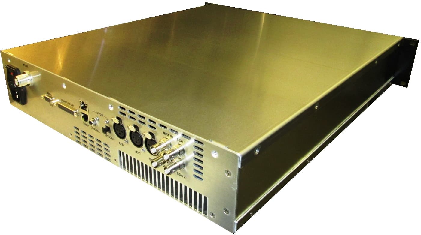
QH5TXF300
May 08, 2014FM Broadcast Transmitter, 300 Watts
Equipment Class
TBC - Licensed Broadcast Station Transmitter
QH5TXUD1000
May 24, 20111000 W Digital TV Transmitter
Equipment Class
TBC - Licensed Broadcast Station Transmitter