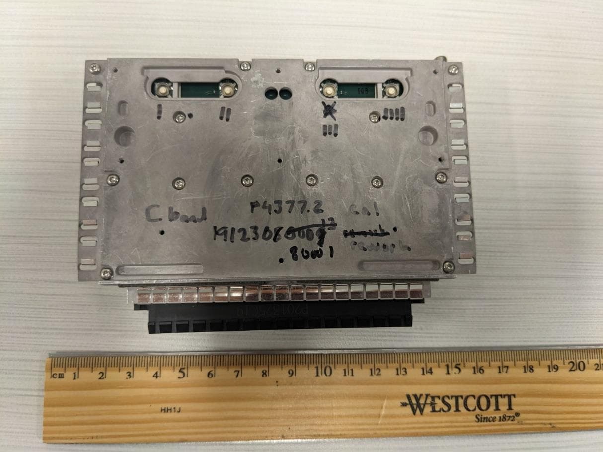
QHYRPM-A5A11-B05The OneCell RP5100 LTE Band 5
CommScope Technologies LLC
Click to zoom
Application Details
- Equipment Class
- TNB - Licensed Non-Broadcast Station Transmitter
- Date of Grant
- Dec 02, 2020
- Application Purpose
- Original Equipment
- Date of Application
- Dec 02, 2020
- Equipment Note
- The OneCell RP5100 LTE Band 5
- Frequency Range
- 874.00000000 - 889.00000000
- Company
- CommScope Technologies LLC
- Country
- United States
Documents & Files
Document Text
Text extracted from the exhibit documents filed with the FCC. Open a document above to read the original.
Users Manual
CommScope Technologies LLC RF Exposure Exhibit SCOPE OF WORK EMC TESTING – Band 5 Radio Module, Model: RPM-A5A11-B05 REPORT NUMBER 104326151MPK-002 ISSUE DATE October 30, 2020 REVISED DATE N/A PAGES 9 DOCUMENT CONTROL NUMBER Non-Specific Radio Report Shell Rev. December 2017 MPK © 2017 INTERTEK Non-Specific Radio Report Shell Rev. December 2017 MPK EMC Report for CommScope Technologies LLC on the Model: RPM-A5A11-B05 Page 2 of 9 RF Exposure Exhibit (mobile devices) Report Number: 104326151MPK-002 Project Number: G104326151 Report Issue Date: October 30, 2020 Product Designation: Model Tested: Band 5 Radio Module RPM-A5A11-B05 FCC ID: QHYRPM-A5A11-B05 to 47CFR 2.1091 for CommScope Technologies LLC Tested by: Client: Intertek 1365 Adams Court Menlo Park, CA 94025 USA CommScope Technologies LLC 250 Apollo Drive Chelmsford, MA 01824 Report prepared by: Report reviewed by: Minh Ly / Project Engineer Krishna Vemuri / EMC Manager This report is for the exclusive use of Intertek's Client and is provided pursuant to the agreement between Intertek and its Client. Intertek's responsibility and liability are limited to the terms and conditions of the agreement. Intertek assumes no liability to any party, other than to the Client in accordance with the agreement, for any loss, expense or damage occasioned by the use of this report. Only the Client is authorized to permit copying or distribution of this report and then only in its entirety. Any use of the Intertek name or one of its marks for the sale or advertisement of the tested material, product or service must first be approved in writing by Intertek. The observations and test results in this report are relevant only to the sample tested. This report by itself does not imply that the material, product, or service is or has ever been under an Intertek certification program. REPORT NUMBER: 104326151MPK-002 Issued: October 30, 2020 Non-Specific Radio Report Shell Rev. December 2017 MPK EMC Report for CommScope Technologies LLC on the Model: RPM-A5A11-B05 Page 3 of 9 Report No. 104326151MPK-002 Equipment Under Test: Band 5 Radio Module Trade Name: CommScope Technologies LLC Model(s) Tested: RPM-A5A11-B05 Applicant: CommScope Technologies LLC Contact: Elowra Khan Address: CommScope Technologies LLC 250 Apollo Drive Chelmsford, MA 01824 Country: USA Tel. Number: (972) 952-9846 Email: [email protected] Applicable Regulation: 47CFR 2.1091 REPORT NUMBER: 104326151MPK-002 Issued: October 30, 2020 Non-Specific Radio Report Shell Rev. December 2017 MPK EMC Report for CommScope Technologies LLC on the Model: RPM-A5A11-B05 Page 4 of 9 TABLE OF CONTENTS CommScope Technologies LLC .......................................................................................................................... 1 1.0 RF Exposure Summary ................................................................................................................... 5 2.0 RF Exposure Limits ........................................................................................................................ 5 3.0 Test Results (Mobile Configuration) ............................................................................................. 6 4.0 Document History ........................................................................................................................... 9 REPORT NUMBER: 104326151MPK-002 Issued: October 30, 2020 Non-Specific Radio Report Shell Rev. December 2017 MPK EMC Report for CommScope Technologies LLC on the Model: RPM-A5A11-B05 Page 5 of 9 1.0 RF Exposure Summary Test Reference FCC Result Radio frequency Radiation Exposure Evaluation 47 CFR§2.1091 Complies 2.0 RF Exposure Limits In this document, we evaluate the RF Exposure to human body due the intentional transmission from the transmitter (EUT). The limits for Maximum Permissible Exposure (MPE) specified in FCC 1.1310 was followed. 2.1 FCC Limits According to FCC 1.1310 table 1: The criteria listed in the following table shall be used to evaluate the environmental impact of human exposure to radio-frequency (RF) radiation as specified in 1.1307(b) LIMITS FOR MAXIMUM PERMISSIBLE EXPOSURE (MPE) Frequency Range (MHz) Electric Field Strength (V/m) Magnetic Field Strength (A/m) Power Density (mW/cm 2 ) Average Time (minutes) (A)Limits For Occupational / Control Exposures 0.3 – 3.0 614 1.63 *100 6 3.0 – 30 1842/f 4.89/f *900/f 2 6 30-300 61.4 0.163 1.0 6 300 - 1500 ... ... F/300 6 1500 - 100,000 ... ... 5 6 (B)Limits For General Population / Uncontrolled Exposure 0.3 – 1.34 614 1.63 *100 30 1.34 – 30 824/f 2.19/f *180/f 2 30 30 – 300 27.5 0.073 0.2 30 300 - 1500 ... ... F/1500 30 1500 - 100,000 ... ... 1.0 30 F = Frequency in MHz * = plane wave equivalent density REPORT NUMBER: 104326151MPK-002 Issued: October 30, 2020 Non-Specific Radio Report Shell Rev. December 2017 MPK EMC Report for CommScope Technologies LLC on the Model: RPM-A5A11-B05 Page 6 of 9 3.0 Test Results (Mobile Configuration) 3.1 Classification Radio is installed inside a mobile host device. The antenna of the product, under normal use condition, is at least 20 cm away from the body of the user and accessible to the end user. Warning statement to the user for keeping at least 20 cm or more separation distance with the antenna should be included in user’s manual. 3.2 EIRP calculations The EUT, Model: RPM-A5A11-B05 consists of Band 5 Radio module only. For RF exposure compliance refer reports # 104326151MPK-001 . 3.3 Maximum RF Power Frequency Range (MHz) RF Output (dBm) Antenna Gain 1 (dBi) Note 864 - 894 21.58 3.0 Conducted power measurements were taken from Report # 104326151MPK-001. 1 As declared by the manufacturer. REPORT NUMBER: 104326151MPK-002 Issued: October 30, 2020 Non-Specific Radio Report Shell Rev. December 2017 MPK EMC Report for CommScope Technologies LLC on the Model: RPM-A5A11-B05 Page 7 of 9 3.4 RF Exposure Calculation 3.4.1 RF Exposure calculation for RPM-A5A11-B05 radio. Calculations for this report are base…
Text truncated - open the document above for the full version.
Users Manual
DRAFT Hardware Installation Guide Release 4.5 Document Number: M0303A2 OneCell ® Document Revision: 4.5.01 Date: September 2020 iiM0303A2 4.5.01 September 2020 D R A F T Copyright 2020 CommScope, All rights reserved. THIS DOCUMENT HAS BEEN DEVELOPED BY COMMSCOPE, AND IS INTENDED FOR THE USE OF ITS CUSTOMERS AND CUSTOMER SUPPORT PERSONNEL. THE SPECIFICATIONS AND INFORMATION REGARDING THE PRODUCTS IN THIS MANUAL ARE SUBJECT TO CHANGE WITHOUT NOTICE. ALL STATEMENTS, INFORMATION, AND RECOMMENDATIONS IN THIS MANUAL ARE BELIEVED TO BE ACCURATE BUT ARE PRESENTED WITHOUT WARRANTY OF ANY KIND, EXPRESS OR IMPLIED. USERS MUST TAKE FULL RESPONSIBILITY FOR THEIR APPLICATION OF ANY PRODUCTS. THE SOFTWARE LICENSE AND LIMITED WARRANTY FOR THE ACCOMPANYING PRODUCT ARE SET FORTH IN THE INFORMATION PACKET THAT SHIPPED WITH THE PRODUCT AND ARE INCORPORATED HEREIN BY REFERENCE. IF YOU ARE UNABLE TO LOCATE THE SOFTWARE LICENSE OR LIMITED WARRANTY, CONTACT YOUR COMMSCOPE SALES REPRESENTATIVE FOR A COPY. OneCell ® Hardware Installation, Release 4.5 iii D R A F T Contents Document revision history About this document Audience....................................................................................................................xiii Purpose.......................................................................................................................xiii What you need to know.............................................................................................xiii Customer documentation...........................................................................................xiii Conventions...............................................................................................................xiv Notes, cautions, and warnings ...................................................................................xvi PART 1 OVERVIEW AND PREPARATION Chapter 1 CommScope OneCell® overview Overview....................................................................................................................1-2 CommScope OneCell system ....................................................................................1-2 OneCell hardware components..................................................................................1-3 Baseband Controller physical ports.....................................................................1-3 Chapter 2 Preparing to install the OneCell system Overview....................................................................................................................2-2 Before installing the OneCell components................................................................2-2 Commissioning the OneCell network........................................................................2-2 PART 2 ONECELL COMPONENT INSTALLATION Chapter 3 Baseband Controller installation Preparing for Baseband Controller installation..........................................................3-2 Installing the Baseband Controller into a rack...........................................................3-2 Chapter 4 RP5100i installation RP5100i installation overview...................................................................................4-2 Ceiling mount.............................................................................................................4-3 Contents ivM0303A2 4.5.01 September 2020 D R A F T Mounting the Radio Point on the ceiling tile ......................................................4-5 Mounting the Radio Point above the ceiling tile...............................................4-15 Flown mount............................................................................................................4-22 Flown mount installation...................................................................................4-24 Pole mount...............................................................................................................4-31 Pole mount installation......................................................................................4-31 Chapter 5 RP5100r installation Rugged Radio Point installation overview ................................................................5-2 Pole mount installation ..............................................................................................5-4 Vertical pole mount .............................................................................................5-4 Wall mount installation............................................................................................5-10 Chapter 6 RP2000 Installation Indoor Radio Point (RP2000) installation overview..................................................6-2 Ceiling mount.............................................................................................................6-3 Mounting the Radio Point on the ceiling tile ......................................................6-5 Mounting the Radio Point above the ceiling tile...............................................6-13 Flown mount............................................................................................................6-17 Flown mount installation...................................................................................6-18 Pole mount...............................................................................................................6-23 Pole mount installation......................................................................................6-23 Chapter 7 RP2100 Installation Rugged Radio Point (RP2100) installation overview................................................7-2 Pole mount installation ..............................................................................................7-4 Vertical pole mount .............................................................................................7-4 Horizontal pole mount.......................................................................................7-10 Wal…
Text truncated - open the document above for the full version.
Users Manual
D R A F T Part III: Appendices Appendix A Safety Appendix B Installation troubleshooting Appendix C Specifications Appendix D Field Replaceable Units Appendix E Cable installation and power separation guidelines D R A F T OneCell ® Hardware Installation, Release 4.5A-1 D R A F T Appendix A Safety This appendix contains specifications for CommScope OneCell, including FCC information and technical data. Radiation Exposure StatementA-2 Human exposure limits for OneCell deploymentsA-2 Chapter ASafety A-2M0303A2 4.5.01 September 2020 D R A F T Radiation Exposure Statement Important: Changes or modifications not expressly approved by CommScope LLC could void your authority to operate the equipment. FCC Part 15 The Baseband Controller and RP5100 have been tested and found to comply with the limits for Class A equipment, pursuant to Part 15 of the FCC Rules. NOTE This equipment has been tested and found to comply with the limits for a Class A digital device, pursuant to part 15 of the FCC Rules. These limits are designed to provide reasonable protection against harmful interference when the equipment is operated in a commercial environment. This equipment generates, uses, and can radiate radio frequency energy and, if not installed and used in accordance with the instruction manual, may cause harmful interference to radio communications. Operation of this equipment in a residential area is likely to cause harmful interference in which case the user will be required to correct the interference at his own expense. For more information, see the publication femtocells and Health at http:// www.femtoforum.org or visit the FCC website at www.fcc.gov. EN55032 WARNING This equipment is compliant with Class A of EN55032. In a residential environment, this equipment may cause radio interference. Human exposure limits for OneCell deployments The human exposure limits for the OneCell product is calculated by using the Maximum Permissible Exposure (MPE) method associated with fixed-type transmitter devices at a minimum exposure distance of 20 cm. Table A-1 includes values for one Radio Point (RP5000 series) and four Radio Points per chassis. Chapter ASafety OneCell ® Hardware Installation, Release 4.5A-3 D R A F T Table A-1. RF exposure for OneCell at maximum power internal antennas for RP5000 series Parameter RPM-A5A11- B66 RPM-A5A11- B02 RPM-I5A11- B01 RPM-I5A11- B03 RPM-I5A11- B07 Tx Power (dBm) per antenna 24.1324.2324.2524.0024.70 Tx Loss (dB)00000 Tx Antenna Gain (dBi)44444 Transmitter Duty Cycle % 100100100100100 Number of Antennas (MIMO) 22222 Contribution due to multiple antennas (dB) 3.01033.01033.01033.01033.0103 Derived Total EIRP (dBW)1.1401.2401.2601.0101.710 Bands662137 Frequency Range (MHz)2110-22001930-19902110-21701805-18802620-2690 Point Source Total EIRP (watts) 1.3001.3311.3371.2621.483 Power Density (W/m2) @ 20 cm 2.5872.6472.5692.5102.950 1. For persons with implants, the maximum calculated distance of 30cm. This applies to any combination of up to four radio modules in Bands 1,3 and 7. 2. For general public and workers, a measured distance of 5mm was determined. This applies to any combination of up to four radio modules in Bands 1,3 and 7. For general public and workers, a calculated distance of 20cm was determined. This applies to any combination of up to four radio modules in Bands 2 and 66. Parameter RPM-I5A11- B17 RPM-A5A11- B12 RPM-A5A11- B14 RPM-A5A11- B05 RPM-A5A11- B30 Tx Power (dBm) per antenna 21.7021.8821.4521.580.00 Tx Loss (dB)00000 Tx Antenna Gain (dBi)44425 Transmitter Duty Cycle % 100100100100100 Chapter ASafety A-4M0303A2 4.5.01 September 2020 D R A F T Table A-2 includes values for one Radio Point (RP2000 and RP2100) and four Radio Points per chassis. Number of Antennas (MIMO) 22222 Contribution due to multiple antennas (dB) 3.01033.01033.01033.01033.0103 Derived Total EIRP (dBW)-1.290-1.110-1.540-3.410-21.990 Bands121214530 Frequency Range (MHz)734-746729 - 746758 - 768869-8942350-2360 Point Source Total EIRP (watts) 0.7430.7750.7020.4560.006 Power Density (W/m2) @ 20 cm 1.4781.5411.3960.9070.013 Parameter RPM-I5A11- B17 RPM-A5A11- B12 RPM-A5A11- B14 RPM-A5A11- B05 RPM-A5A11- B30 Table A-2. RF exposure for OneCell at maximum power internal antennas for RP2000 series Parameter Indoor RP-A2014 & RP-I2014 Rugged RP-A2114 & RP-I2114 Tx Power (dBm) per antenna212121212121 Tx Loss (dB)000000 Tx Antenna Gain (dBi)0511.81212.513.5 Transmitter Duty Cycle % 100100100100100100 Number of Antennas (MIMO)222222 Contribution due to multiple antennas (dB) 3.01033.01033.01033.01033.01033.0103 Derived Total EIRP (dBW)-5.990-0.9905.8106.0106.5107.510 Bands12,13,17 1,2,3,4,7,10,25 12,13,1731,2,4,10,25 2620- 2690 Frequency Range (MHz)729-7561805-2690729-756 1805-1880 1930-2170 2620- 2690 Point Source Total EIRP (watts)0.2520.7963.8113.9914.4775.637 Power Density (W/m2) @ 20 cm 0.5011.5847.5827.9398.90811.214 Chapter ASafety OneCell ® Hardware Installation, Release 4.5A-5 D R A F T Reference documents [1] Federal Communications Commission Document OET Bulletin 65, Supplement C, 2001, Evaluating Compliance with FCC guidelines for Human Exposure to radio frequency Electromagnetic Fields, US Federal Communications Commission, Office of Engineering and Technology June 2001. [2] Federal Communications Commission Document OET Bulletin 56, “Questions and answers about biological effects and potential hazards of radio frequency electromagnetic fields”, Federal Communications Commission Office of Engineering and Technology, August 1999. [3] ICNIRP Guidelines for limiting exposure to time varying electric, magnetic and electromagnetic fields up to 300 GHz. International Commission on Non Ionizing Radiation, published in Health Physics 74 (4): 494-522; 1998 [4] ICNIRP Statement on EMF-Emitting New Technologies, International Commission on Non-Ionizing Radiation, published in Health Physics 94 (4):376-392, 2008 [5] 3GPP Document 3GPP TS 36.104 version 10.11.0 Release 10,” LTE Evolved Universal Terr…
Text truncated - open the document above for the full version.
Users Manual
OneCell ® Hardware Installation, Release 4.5E-1 D R A F T Appendix E Cable installation and power separation guidelines This section contains best practices for installing Ethernet cables and connecting them to RPs. OverviewE-2 Cable handlingE-2 Cable terminationE-3 Lightning protectionE-12 Ceiling connectorE-15 Patch panelE-17 Power separation guidelinesE-17 Appendix ECable installation and power separation guidelines E-2M0303A2 4.5.01 September 2020 D R A F T Overview When installing Rugged RPs, cables that can withstand temperature extremes and inclement weather should be used. In outside environments, avoid contamination or damage to plugs. Plugs must be protected from sunlight and water in a suitable equipment housing or NEMA 4 rated box. It is also important to avoid exposure to water at cut ends of unfilled cables and cords. The following information is available to help you extend the operation of your RP and switches. Cable handling Indoor/outdoor cords can be routed outdoors above ground and indoors, and can be ordered in lengths long enough for direct (home-run) installations from switch to end equipment. Cords have 20% Insertion Loss De-rating so only 85 meters total can be supported. Extended lengths can be cut in two for terminating the indoor ends at protectors or panels. Terminations are similar to typical 4-pair indoor cables. Unreel long lengths of cable to ensure the cable does not become twisted or caught on objects. Figure E-1. Unreel cable CommScope recommends using a sock fitted and secured over the plug to pull cable through long conduits. Sock information Tie wrap information Appendix ECable installation and power separation guidelines OneCell ® Hardware Installation, Release 4.5E-3 D R A F T Figure E-2. Cable with sock attached using tie wrap Feed the sock through the conduit and secure the sock on the terminal end of the cable with the tie-wrap. Once the sock and tie-wrap are in place, pull the cable through the conduit. Cable termination Before installing the Rugged RP, terminate the RP end of the Ethernet cable with the RJ45, IP67 connector provided in the box. Figure E-3. RJ45, IP67 connector Flip the plug anti-snag to make it easier to push through the cord grips (flip it back before plugging in). Sock Tie-wrap Conduit Appendix ECable installation and power separation guidelines E-4M0303A2 4.5.01 September 2020 D R A F T Use the split grommet provided. Once it is in place, coat it with silicone to ensure the connector is sealed. Figure E-4. Assembling the connector on the RP end Cable splicing Some cables are run in one piece from source to destination and have connector terminations. In other cases, two shorter pieces of cable need to be spliced together. When a cable is run to outdoor devices, you should take measures to ensure that cables are properly protected against moisture entering the cable. This is especially important when the jacket is stripped back from the wires. Some cables are gel filled and the termination includes cleaning the excess gel and blocking the end with silicone sealant to prevent future leakage. A typical blocking method uses a 2 cm length of Alpha Wire PVC-105-2 tubing or equivalent. 1Fill all space inside the tubing with B-sealant. Appendix ECable installation and power separation guidelines OneCell ® Hardware Installation, Release 4.5E-5 D R A F T 2Position the filled tube to overlap the end of the inner jacket and seal the gel. Clean off all excess sealant. NOTE: Tape can be used to stabilize the tube for immediate termination before the sealant sets. Cable termination Shielded cables must be properly terminated, either grounded or isolated. For exposed installations requiring protection, the end of the shield can be bonded in various ways. The following procedure is an example of one method. 1Make a slit along the length of the jacket. Be careful not to tear the underlying shielding. Appendix ECable installation and power separation guidelines E-6M0303A2 4.5.01 September 2020 D R A F T 2Pull back the jacket along the slit and remove. Appendix ECable installation and power separation guidelines OneCell ® Hardware Installation, Release 4.5E-7 D R A F T 3Fold back the foil shielding and drain wire to expose the inner jacket. 4Prepare the inner jacket for blocking the gel and direct burial. aCut back the inner jacket bTrim the flute cClean the excess gel NOTE: The flute can be cut longer to match the blocking tube length. Appendix ECable installation and power separation guidelines E-8M0303A2 4.5.01 September 2020 D R A F T 5Fill all space inside the tubing with B-sealant and position the filled tube to overlap the end of the inner jacket and seal the gel. 6Fold the drain wire and foil back over the tube and position the foil to be folded back over the tube. Appendix ECable installation and power separation guidelines OneCell ® Hardware Installation, Release 4.5E-9 D R A F T 7An extra piece of foil can be used to cover the foil seam. 8For an HGS620 termination, wrap the drain wire at least two times around and position it where the spring clips will capture them. 9Tape over the foil for stability. 10Trim the wire ends. Appendix ECable installation and power separation guidelines E-10M0303A2 4.5.01 September 2020 D R A F T Cable grounding For CAT-6A cables, the shield termination method is to use the ground lug and B- bond clip that are available in the 12A1 Grounding Kit. 1Fold the foil back over the jacket end and wrap the drain wire around the end and push the ground lug over the wrap. Appendix ECable installation and power separation guidelines OneCell ® Hardware Installation, Release 4.5E-11 D R A F T 2Open the B-bonding clip to be placed and closed over the grounding lug. 3The lug tail can be cut off or used for ground attachment. 4Treat the inner jacket as described in step 4 on page E-7 . Appendix ECable installation and power separation guidelines E-12M0303A2 4.5.01 September 2020 D R A F T For an isolated shield termin…
Text truncated - open the document above for the full version.
Cover Letter(s)
900 Chelmsford St Lowell, MA 01851 T: +1 978-250-2678 FCC Confidentiality Request Letter 10/27/2020 To: Federal Communications Commission 7435 Oakland Mills Road Columbia, MD 21046-1609 Intertek TCB 70 Codman Hill Road Boxborough, MA 01719 Re: Confidentiality Request FCC ID QHYRPM-A511-B05 Pursuant to Sections 0.457(d)(1)(ii) and 0.459 of the Commission’s Rules, CommScope Technologies LLC hereby requests permanent confidential treatment of information accompanying this application as outlined below: 1. Parts List/Bill of Materials 2. Schematic Diagrams 3. Circuit/Technical Description 4. Block Diagram CommScope Technologies LLC. also, hereby requests short-term confidential treatment of information accompanying this application as outlined below for a period of 180 days: 1. External and Internal Photos 2. Test photos 3. User Manual The above materials contain trade secrets and proprietary information not customarily released to the public. The public disclosure of these matters might be harmful to the Applicant and provide unjustified benefits to its competitors. The Applicant understands that pursuant to Rule 0.457(d)(1)(ii), disclosure of this Application and all accompanying materials will not be made before the date of the Grant for this Application. Sincerely, ___________________________ Kevin Craig Consulting Mechanical Engineer 10/27/2020
Cover Letter(s)
250 Apollo Drive Suite 100 Chelmsford, MA 01824 T: +1 978-250-3000 Agent’s Authorization Letter 8/1/2019 I do hereby authorize, until further notice, Intertek, 70 Codman Hill Rd, Boxborough, MA 01719, to act on our behalf in dealings before the Federal Communications Commission with respect to all matters relating to equipment authorizations under 47 CFR. This authorization includes, but is not limited to, the signing of Form 731. I certify that no party (as defined in 47 CFR 1.2002) to this application, including myself, is subject to a denial of federal benefits, that include FCC benefits, pursuant to section 5301 of the Anti-Drug Abuse Act of 1988, 21 U.S.C., 853A. Certified By: __________________ Kevin Craig Consulting Engineer. 8/1/2019
External Photos
External Photos FCC ID: QHYRPM-A5A11-B05
Internal Photos
Internal Photos FCC ID: QHYRPM-A5A11-B05
Parts List/Tune Up Info
900 Chelmsford St Lowell, MA 01851 T: +1 978-250-2678 Tune Up Procedure Declaration 4/20/2020 To: Intertek TCB 70 Codman Hill Road Boxborough, MA 01719 Gentlemen: This letter declares that the product associated with the submission of FCC ID QHYRPM-A5A11-B05 does not require any tune up procedure for proper operation. Sincerely, Kevin Craig Consulting Mechanical Engineer 04/20/2020
Test Report
CommScope Technologies, LLC TEST REPORT SCOPE OF WORK EMISSIONS TESTING – Band 5 Radio Module, Model: RPM-A5A11-B05 REPORT NUMBER 104326151MPK-010 ISSUE DATE [REVISED DATE] August 25, 2020 N/A PAGES 154 DOCUMENT CONTROL NUMBER Non-Specific Radio Report Shell Rev. December 2017 © 2017 INTERTEK Non-Specific Radio Report Shell Rev. December 2017 Page 2 of 154 EMC Report for CommScope Technologies LLC / Model: RPM-A5A11-B05 TEST REPORT (FULL COMPLIANCE) Report Number: 104326151MPK-010 Project Number: G104326151 Report Issue Date: August 25, 2020 Product Designation: Model Tested: Band 5 Radio Module RPM-A5A11-B05 Standards: CFR47 FCC Part 22 FCC ID: QHYRPM-A5A11-B05 Tested by: Client: Intertek Testing Services NA, Inc. 1365 Adams Court Menlo Park, CA 94025 USA CommScope Technologies LLC 250 Apollo Drive Chelmsford, MA 01824 USA Report prepared by Report reviewed by Minh Ly / EMC Project Engineer Krishna Vemuri/ EMC Manager This report is for the exclusive use of Intertek's Client and is provided pursuant to the agreement between Intertek and its Client. Intertek's responsibility and liability are limited to the terms and conditions of the agreement. Intertek assumes no liability to any party, other than to the Client in accordance with the agreement, for any loss, expense or damage occasioned by the use of this report. Only the Client is authorized to permit copying or distribution of this report and then only in its entirety. Any use of the Intertek name or one of its marks for the sale or advertisement of the tested material, product or service must first be approved in writing by Intertek. The observations and test results in this report are relevant only to the sample tested. This report by itself does not imply that the material, product, or service is or has ever been under an Intertek certification program. Intertek Report Number: 104326151MPK-010 Issued: August 25, 2020 Non-Specific Radio Report Shell Rev. December 2017 Page 3 of 154 EMC Report for CommScope Technologies LLC / Model: RPM-A5A11-B05 Table of Contents CommScope Technologies, LLC .................................................................................................................................. 1 1 Introduction and Conclusion .............................................................................................................. 4 2 Test Summary ...................................................................................................................................... 4 3 Client Information ................................................................................................................................ 5 4 Description of Equipment Under Test and Variant Models ............................................................. 5 5 System Setup and Method .................................................................................................................. 7 6 Effective Radiated Power .................................................................................................................... 9 7 Peak-to-Average Power Ratio (PAPR) ............................................................................................. 37 8 26 dB Bandwidth and Occupied Bandwidth ................................................................................... 65 9 Band Edge Compliance ............................................................…
Text truncated - open the document above for the full version.
Contact Information
Applicant
Zac Johnson(Regulatory Engineer)
Technical Contact
CommScope Technologies LLCKevin Eric Craig
[email protected]978-614-3182
Cross Point Tower · Lowell · United States
Non-Technical Contact
CommScope Technologies LLCTom Naughton
[email protected]978-614-3197
Test Firm
IntertekTesting Services NA Inc.Charles Parker
Technical Specifications
| # | Rule Parts | Frequency Range | Power Output | Emission | Tolerance |
|---|---|---|---|---|---|
| 2 | 22H | 874 MHz - 889 MHz | 141.00 mW | 9M01G7D | 1 ppm |
Other Applications from CommScope Technologies LLC
QHYRPM-A5A11-N77
May 01, 2023The OneCell RP5200 5G Band n77, BW, P3 rev
Equipment Class
TNB - Licensed Non-Broadcast Station Transmitter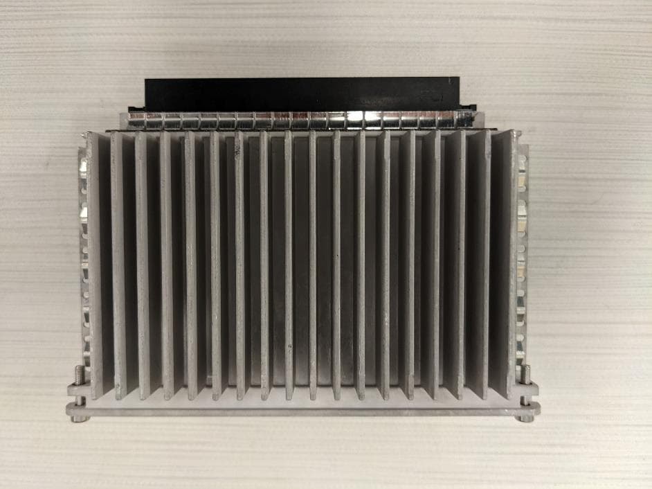
QHYRPM-A5A11-N77C
Aug 30, 2022The OneCell RP5200 5G Band n77, 40MHz BW
Equipment Class
TNB - Licensed Non-Broadcast Station Transmitter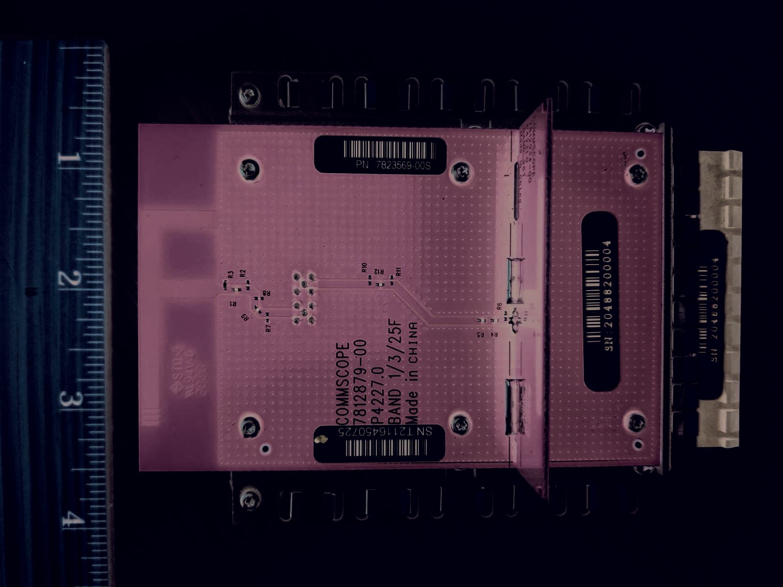
QHYRPM-A5A11-B25
Apr 04, 2022The OneCell RP5200 B25 / B2 Radio.
Equipment Class
PCB - PCS Licensed Transmitter
QHYRPM-A5A11-B30
Dec 15, 2020The OneCell RP5100 LTE Band 30
Equipment Class
TNB - Licensed Non-Broadcast Station Transmitter
QHYRPM-A5A11-B12
Jan 20, 2020OneCell Radio Point
Equipment Class
TNB - Licensed Non-Broadcast Station Transmitter