QHYRPM-A5A11-N77CThe OneCell RP5200 5G Band n77, 40MHz BW
CommScope Technologies LLC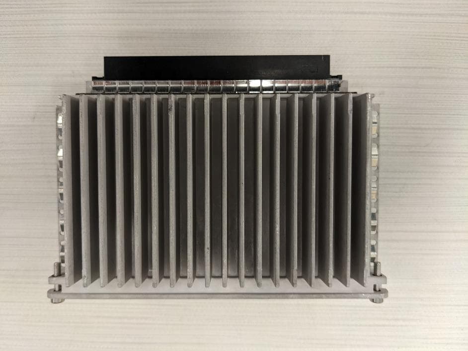
Click to zoom
Application Details
- Equipment Class
- TNB - Licensed Non-Broadcast Station Transmitter
- Date of Grant
- Aug 30, 2022
- Application Purpose
- Original Equipment
- Date of Application
- Aug 29, 2022
- Equipment Note
- The OneCell RP5200 5G Band n77, 40MHz BW
- Frequency Range
- 3720.00000000 - 3960.00000000
- Company
- CommScope Technologies LLC
- Country
- United States
Documents & Files
Document Text
Text extracted from the exhibit documents filed with the FCC. Open a document above to read the original.
Users Manual
DRAFT ONECELL ® Hardware Installation Guide Release 6.5 P/N M0305AN, Rev. A August 2022 iiM0305AN, Rev. A Release 6.5 August 2022 D R A F T Copyright 2022 CommScope, All rights reserved. THIS DOCUMENT HAS BEEN DEVELOPED BY COMMSCOPE, AND IS INTENDED FOR THE USE OF ITS CUSTOMERS AND CUSTOMER SUPPORT PERSONNEL. THE SPECIFICATIONS AND INFORMATION REGARDING THE PRODUCTS IN THIS MANUAL ARE SUBJECT TO CHANGE WITHOUT NOTICE. ALL STATEMENTS, INFORMATION, AND RECOMMENDATIONS IN THIS MANUAL ARE BELIEVED TO BE ACCURATE BUT ARE PRESENTED WITHOUT WARRANTY OF ANY KIND, EXPRESS OR IMPLIED. USERS MUST TAKE FULL RESPONSIBILITY FOR THEIR APPLICATION OF ANY PRODUCTS. THE SOFTWARE LICENSE AND LIMITED WARRANTY FOR THE ACCOMPANYING PRODUCT ARE SET FORTH IN THE INFORMATION PACKET THAT SHIPPED WITH THE PRODUCT AND ARE INCORPORATED HEREIN BY REFERENCE. IF YOU ARE UNABLE TO LOCATE THE SOFTWARE LICENSE OR LIMITED WARRANTY, CONTACT YOUR COMMSCOPE SALES REPRESENTATIVE FOR A COPY. ONECELL ® Hardware Installation Guide, Release 6.5 iii D R A F T Contents Document revision history About this document Audience.....................................................................................................................xv Purpose........................................................................................................................xv What you need to know..............................................................................................xv Customer documentation............................................................................................xv Conventions..............................................................................................................xvii Notes, cautions, and warnings .................................................................................xviii PART 1 OVERVIEW AND PREPARATION Chapter 1 CommScope ONECELL® overview Overview....................................................................................................................1-2 CommScope ONECELL system................................................................................1-2 ONECELL hardware components.............................................................................1-3 Baseband Controller physical ports.....................................................................1-3 Chapter 2 Preparing to install the ONECELL system Overview....................................................................................................................2-2 Before installing the ONECELL components ...........................................................2-2 Commissioning the ONECELL network...................................................................2-2 PART 2 ONECELL COMPONENT INSTALLATION Chapter 3 Baseband Controller installation Preparing for Baseband Controller installation..........................................................3-2 Installing the Baseband Controller into a rack...........................................................3-2 Chapter 4 RP5200i installation RP5200i installation overview...................................................................................4-2 Ceiling mount.............................................................................................................4-3 Contents ivM0305AN, Rev. A Release 6.5 August 2022 D R A F T Mounting the Radio Point on the ceiling tile ......................................................4-4 Wall mount...............................................................................................................4-12 Mounting the Radio Point on the wall...............................................................4-13 Flown Mount............................................................................................................4-23 Flown mount installation...................................................................................4-24 Pole mount...............................................................................................................4-29 Pole mount installation......................................................................................4-31 Chapter 5 RP5100i installation RP5100i installation overview...................................................................................5-2 Ceiling mount.............................................................................................................5-3 Mounting the Radio Point on the ceiling tile ......................................................5-5 Mounting the Radio Point above the ceiling tile...............................................5-15 Flown mount............................................................................................................5-22 Flown mount installation...................................................................................5-24 Pole mount...............................................................................................................5-31 Pole mount installation......................................................................................5-31 Chapter 6 RP5100r installation Rugged Radio Point installation overview ................................................................6-2 Antenna port label...............................................................................................6-4 Pole mount installation ..............................................................................................6-4 Vertical pole mount .............................................................................................6-5 Wall mount installation............................................................................................6-10 Chapter 7 RP2000 Installation Indoor Radio Point (RP2000) installation overview..................................................7-2 Ceiling mount.............................................................................................................7-3 Mo…
Text truncated - open the document above for the full version.
Users Manual
Chapter 5RP5100i installation 5-2M0305AN, Rev. A Release 6.5 August 2022 D R A F T RP5100i installation overview The RP5100i is the Radio Point for indoor solutions. There are four configurations for installing the RP5100i, which are dependent on the ceiling type. • Ceiling mount, on tile • Ceiling mount, above tile • Flown mount • Pole mount NOTE Once the Radio Point is installed and powered on, it may take up to 20 minutes for the frequency to stabilize and lock. NOTE If the MR port is connected to a switch that does not provide IEEE802.3bt, type-4 PoE power, the SR port can be used to provide power with a PoE++ injector. For more information, see ONECELL ® Network Planning Guide, v6.5 (M0306AN). Chapter 5RP5100i installation ONECELL ® Hardware Installation Guide, Release 6.55-3 D R A F T Ceiling mount Mounting the Radio Point (RP) above or on the ceiling tile requires the following hardware provided by CommScope: • Radio Point plate and screws • 4" octagon box, 1-1/2" deep with 1/2" side cutouts • Clamp and screw Figure 5-1. CommScope ceiling mount kit contents Octagon box Mounting plate for octagon box with 2 screws Mounting plate for RP with 4 screws Chapter 5RP5100i installation 5-4M0305AN, Rev. A Release 6.5 August 2022 D R A F T Mounting the Radio Point (RP) above or on the ceiling tile requires the following hardware provided by the system integrator: • Drop rail – Eaton B-line BA50A or equivalent, with a static load capacity of at least 25 lbs without a drop wire, recommended Figure 5-2. Drop rail, system integrator-provided Drop rail Clamp 2 screws Chapter 5RP5100i installation ONECELL ® Hardware Installation Guide, Release 6.55-5 D R A F T Mounting the Radio Point on the ceiling tile 1Remove two ceiling tiles from the overhead. 2Place the octagon box on the tile and trace the outline. Cut the opening. 3Drill a 1/2-inch diameter hole for the Ethernet cable pass-through. NOTE: Use a 1-1/2 deep RACO 8125 or equivalent. Chapter 5RP5100i installation 5-6M0305AN, Rev. A Release 6.5 August 2022 D R A F T 4Attach the octagon box to the ceiling bracket using a clamp and screw. 70 mm (2.7”) 138 mm (5.4”) Octagon box Screws Drop ceiling rail Clamp Chapter 5RP5100i installation ONECELL ® Hardware Installation Guide, Release 6.55-7 D R A F T 5Replace the ceiling tile with the cutouts. Chapter 5RP5100i installation 5-8M0305AN, Rev. A Release 6.5 August 2022 D R A F T 6Install the drop rail/octagon box assembly over the modified tile. Chapter 5RP5100i installation ONECELL ® Hardware Installation Guide, Release 6.55-9 D R A F T 7Attach the mounting plate onto the octagon box and feed the Ethernet cable through the small hole in the ceiling tile. Ethernet cable Mounting plate Chapter 5RP5100i installation 5-10M0305AN, Rev. A Release 6.5 August 2022 D R A F T 8Attach base plate to the Radio Point. NOTE: Apply thread locking compound to screws prior to installation. 9Mount the Radio Point on the octagon box plate. Ethernet cable Chapter 5RP5100i installation ONECELL ® Hardware Installation Guide, Release 6.55-11 D R A F T 10Secure Radio Point to the octagon plate. Chapter 5RP5100i installation 5-12M0305AN, Rev. A Release 6.5 August 2022 D R A F T 11Remove the cover from the RP. NOTE: The cover is attached to the RP with two lanyards. Chapter 5RP5100i installation ONECELL ® Hardware Installation Guide, Release 6.55-13 D R A F T 12Connect Ethernet cable to the MR port on the Radio Point. Chapter 5RP5100i installation 5-14M0305AN, Rev. A Release 6.5 August 2022 D R A F T 13Replace plastic cover on the Radio Point. 14Replace the ceiling tile next to the Radio Point. Chapter 5RP5100i installation ONECELL ® Hardware Installation Guide, Release 6.55-15 D R A F T Mounting the Radio Point above the ceiling tile 1Remove ceiling tile from the overhead. Chapter 5RP5100i installation 5-16M0305AN, Rev. A Release 6.5 August 2022 D R A F T 2Attach the octagon box to the bracket. NOTE: CommScope recommends an Eaton B-line – BA50A adjustable bracket. Clamp Drop rail Octagon box Screw Chapter 5RP5100i installation ONECELL ® Hardware Installation Guide, Release 6.55-17 D R A F T 3Attach the bracket to the mounting plate to the octagon box. 4Attach plate to the Radio Point. NOTE: Apply thread locking compound to screws prior to installation. Chapter 5RP5100i installation 5-18M0305AN, Rev. A Release 6.5 August 2022 D R A F T 5Attach the Radio Point to the octagon box mounting plate. Chapter 5RP5100i installation ONECELL ® Hardware Installation Guide, Release 6.55-19 D R A F T 6Install drop rail above the ceiling tile. Chapter 5RP5100i installation 5-20M0305AN, Rev. A Release 6.5 August 2022 D R A F T 7Remove the cover from the RP. NOTE: The cover is attached to the RP with two lanyards. 8Connect the Ethernet cables to the Radio Point MR port. Chapter 5RP5100i installation ONECELL ® Hardware Installation Guide, Release 6.55-21 D R A F T 9Replace the cover on the Radio Point. NOTE: The minimum clearance for cooling is 3 inches. Ceiling tile 3” Chapter 5RP5100i installation 5-22M0305AN, Rev. A Release 6.5 August 2022 D R A F T 10Replace the ceiling tile. Flown mount The Radio Point can be flown mounted on the end of a rod. This configuration is used for building where there are no drop ceilings. Mounting the Radio Point (RP) in the flown configuration requires the following hardware provided by CommScope in the mounting kit: • Radio Point plate and screws • 4" octagon box, 1-1/2" deep with 1/2" side cutouts NOTE: Remove the top, middle cutout. • Clamp and screw – this hardware is not required for the flown mount option Chapter 5RP5100i installation ONECELL ® Hardware Installation Guide, Release 6.55-23 D R A F T Figure 5-3. CommScope flown mount kit contents Mounting the Radio Point (RP) in the flown configuration requires the following hardware provided by the system integrator: • Rod, 3/8-inch threaded • Nut • Lock nut, nylon • Flat washers Octagon box Mounting plate for octagon box with 2 screws Mounting plate for R…
Text truncated - open the document above for the full version.
Users Manual
ONECELL ® Hardware Installation Guide, Release 6.58-1 D R A F T Chapter 8 RP2100 Installation This chapter describes installing Rugged Radio Points on poles and walls. Rugged Radio Point (RP2100) installation overview8-2 Pole mount installation8-4 Wall mount installation8-17 Chapter 8RP2100 Installation ONECELL ® Hardware Installation Guide, Release 6.58-2 D R A F T Rugged Radio Point (RP2100) installation overview The Rugged Radio Point (RP) ships with the following hardware: • Radio Point • Mounting plate • Mounting brackets • Four tamper-resistant mounting screws (M5) • RJ45, IP67 connector • Two 4.3-10 antenna couplers NOTE A tamper-resistant T25 Torx bit, 1/4" hex shank, attached to a driver handle, is required to secure the tamper-resistant mounting screws. Mounting the Radio Point (RP) on a pole requires the following hardware provided by the system integrator: • Two adjustable clamps Chapter 8RP2100 Installation 8-3M0305AN, Rev. A Release 6.5 August 2022 D R A F T Mounting the Radio Point (RP) on a wall requires the following hardware provided by the system integrator: • Four molly screws capable – 50 lb (23 kg) minimum rating Before installing the RP on the pole, terminate the RP end of the Ethernet cable with the RJ45, IP67 connector provided in the box. NOTE Once the Radio Point is installed and the powered on, it may take up to 20 minutes for the frequency to stabilize and lock. Chapter 8RP2100 Installation ONECELL ® Hardware Installation Guide, Release 6.58-4 D R A F T Pole mount installation There are two orientations for pole mount installations: • Vertical pole mount • Horizontal pole mount NOTE The minimum pole diameter requirement is 4'' (102mm). Vertical pole mount 1Attach mounting brackets to mounting plate. NOTE: The torque requirement for the bracket mounting screws is 5-6 in-lbs. 2Slide the adjustable clamp through the slots on each RP mounting bracket on the RP plate. Slide adjustable clamp end through slots Chapter 8RP2100 Installation 8-5M0305AN, Rev. A Release 6.5 August 2022 D R A F T 3Wrap each clamp around the pole and tighten the clamp screw to secure the RP to the pole. Chapter 8RP2100 Installation ONECELL ® Hardware Installation Guide, Release 6.58-6 D R A F T 4Insert two screws into the upper holes on opposite sides of the RP as shown in the drawing below. CAUTION Ensure that the RP is oriented correctly with the two antenna connectors at the top of the RP. Required orientation Chapter 8RP2100 Installation 8-7M0305AN, Rev. A Release 6.5 August 2022 D R A F T 5Hang the RP to the mounting bracket using the installed screws. Align holes at bottom location of bracket. Chapter 8RP2100 Installation ONECELL ® Hardware Installation Guide, Release 6.58-8 D R A F T 6Insert and tighten the bottom screws through the plate hole into both sides of the RP. Be sure that all four screws are tightened. NOTE: The torque requirement for the mounting screws is 20-21 in-lbs. Chapter 8RP2100 Installation 8-9M0305AN, Rev. A Release 6.5 August 2022 D R A F T 7Connect the antenna couplers on the top of the RP. NOTE: Check the antenna coupler manufacturer’s documentation for torque requirements. 8Connect the Ethernet cable RJ45 end to the bottom of the RP. Chapter 8RP2100 Installation 8-10M0305AN, Rev. A Release 6.5 August 2022 D R A F T Horizontal pole mount 1Attach mounting brackets to mounting plate. NOTE: The torque requirement for the bracket mounting screws is 5-6 in-lbs. Chapter 8RP2100 Installation ONECELL ® Hardware Installation Guide, Release 6.58-11 D R A F T 2Slide the adjustable clamp through the slots on each RP mounting bracket on the RP plate. Slide adjustable clamp end through slots Chapter 8RP2100 Installation 8-12M0305AN, Rev. A Release 6.5 August 2022 D R A F T 3Wrap each clamp around the pole and tighten the clamp screw to secure the RP to the pole. 4Insert two screws into the upper holes on opposite sides of the RP as shown in the drawing below. Chapter 8RP2100 Installation ONECELL ® Hardware Installation Guide, Release 6.58-13 D R A F T CAUTION Ensure that the RP is oriented correctly with the two antenna connectors at the top of the RP. Required orientation Chapter 8RP2100 Installation 8-14M0305AN, Rev. A Release 6.5 August 2022 D R A F T 5Hang the RP to the mounting bracket using the installed screws. Align holes at bottom location of bracket and install two additional screws. Chapter 8RP2100 Installation ONECELL ® Hardware Installation Guide, Release 6.58-15 D R A F T 6Insert and tighten the bottom screws through the plate hole into both sides of the RP. Be sure that all four screws are tightened. NOTE: The torque requirement for the mounting screws is 20-21 in-lbs. Chapter 8RP2100 Installation 8-16M0305AN, Rev. A Release 6.5 August 2022 D R A F T 7Connect the antenna couplers on the top of the RP. NOTE: Check the antenna coupler manufacturer’s documentation for torque requirements. 8Connect the Ethernet cable RJ45 end to the bottom of the RP. Chapter 8RP2100 Installation ONECELL ® Hardware Installation Guide, Release 6.58-17 D R A F T Wall mount installation 1Drill four holes in the wall using the mounting plate to determine the hole locations. Mount the backplate on the wall with four molly screws. Chapter 8RP2100 Installation 8-18M0305AN, Rev. A Release 6.5 August 2022 D R A F T 2Insert two screws into the upper holes on opposite sides of the RP as shown in the drawing below. Required orientation Chapter 8RP2100 Installation ONECELL ® Hardware Installation Guide, Release 6.58-19 D R A F T 3Attach the RP to the mounting plate. Tighten the top screws on the RP and insert and tighten the bottom screws on the RP. NOTE: The torque requirement for the mounting screws is 20-21 in-lbs. Chapter 8RP2100 Installation 8-20M0305AN, Rev. A Release 6.5 August 2022 D R A F T 4Insert and tighten the bottom screws through the plate hole into both sides of the RP. 5Connect the antenna couplers on the top of the RP. NOTE: Check the antenna coupler manufacturer’s documenta…
Text truncated - open the document above for the full version.
Users Manual
Appendix DField Replaceable Units D-30M0305AN, Rev. A Release 6.5 August 2022 D R A F T 10Verify the RP5200i installation. The operational state of the RP can be determined by the LED status on the RP. Additional information can be attained from the WebGUI status screens. See Post-Install Verification Flown mount 1Remove the RP. Pull downward gently and push in the direction of the LEDs. 2Disconnect the Red and Blue cables from the RJ45 jacks. Appendix DField Replaceable Units ONECELL ® Hardware Installation Guide, Release 6.5D-31 D R A F T 3Remove the RP plate from the failed RP. Set the RP, plate and screws aside. 4Attach the RP plate to the replacement RP. Ensure the label is facing the entry module Appendix DField Replaceable Units D-32M0305AN, Rev. A Release 6.5 August 2022 D R A F T 5Connect the Red Primary and Blue Secondary Ethernet cables to the RP corresponding ports, as shown below. Leave some slack in the cables to avoid stressing the connectors. Appendix DField Replaceable Units ONECELL ® Hardware Installation Guide, Release 6.5D-33 D R A F T 6Lift the RP and insert the Red and Blue RP cables into the Red and Blue RJ45 jacks, respectively. 7Attach the RP to the mounting plate. aAlign the keyhole opening on the mounting plate with the button on the RP mounting plate. bInsert the RP into the mounting plate slot and slide until the RP plate meets the tabs on the octagon box plate. Appendix DField Replaceable Units D-34M0305AN, Rev. A Release 6.5 August 2022 D R A F T Appendix DField Replaceable Units ONECELL ® Hardware Installation Guide, Release 6.5D-35 D R A F T 8Lift the RP vertically and slide it into the locked position. Verify the RF module installation. The operational state of the RF module can be determined by the LED status on the RP. Additional information can be attained from the WebGUI status screens. See Post-Install Verification. Appendix DField Replaceable Units D-36M0305AN, Rev. A Release 6.5 August 2022 D R A F T Pole mount 1Gentlypull the RP forward and slide it upward. 2Tilt the RP forward and disconnect the cables from the RJ45 jacks. Set the RP aside. Appendix DField Replaceable Units ONECELL ® Hardware Installation Guide, Release 6.5D-37 D R A F T 3Attach the plate to the RP. 4Connect the Red Primary and Blue Secondary cables to the corresponding ports on the RP. Leave some slack in the cables to avoid stressing the connectors. Appendix DField Replaceable Units D-38M0305AN, Rev. A Release 6.5 August 2022 D R A F T 5Lift the RP to the pole plate and connect the Red Primary and Blue Secondary cables to the corresponding connectors on the plate. Appendix DField Replaceable Units ONECELL ® Hardware Installation Guide, Release 6.5D-39 D R A F T 6Lift the RP and gently slide it onto the pole mounting plate. 7Slide the RP down and lock into place. Appendix DField Replaceable Units D-40M0305AN, Rev. A Release 6.5 August 2022 D R A F T Verify the RF module installation. The operational state of the RF module can be determined by the LED status on the RP. Additional information can be attained from the WebGUI status screens. See Post-Install Verification. Replacing RP5100 series Radio Points The following procedures provide instructions for replacing a ONECELL Radio Point (RP) module in a live network environment. • Replacing a ceiling RP5100i (above tile) • Replacing a flown mounted RP5100i • Replacing a pole mounted RP5100i • RP post-replacement verification Replacing a ceiling RP5100i (above tile) 1Remove the ceiling tile next to the mounted RP to allow access to the mounting hardware and Ethernet cable. 2Remove the RP cover. Appendix DField Replaceable Units ONECELL ® Hardware Installation Guide, Release 6.5D-41 D R A F T Appendix DField Replaceable Units D-42M0305AN, Rev. A Release 6.5 August 2022 D R A F T 3Disconnect the Ethernet cable. Appendix DField Replaceable Units ONECELL ® Hardware Installation Guide, Release 6.5D-43 D R A F T 4Replace the cover and twist the RP clockwise to remove it. Set the failed RP aside. Appendix DField Replaceable Units D-44M0305AN, Rev. A Release 6.5 August 2022 D R A F T 5Attach the mounting plate to the replacement RP. NOTE: Apply thread locking compound to the screws prior to installation. Appendix DField Replaceable Units ONECELL ® Hardware Installation Guide, Release 6.5D-45 D R A F T 6Attach the RP to the octagonal mounting plate and twist to engage. Appendix DField Replaceable Units D-46M0305AN, Rev. A Release 6.5 August 2022 D R A F T 7Remove the cover and connect the Ethernet cable to the MR port. NOTE: The cover is attached to the RP with two lanyards. Appendix DField Replaceable Units ONECELL ® Hardware Installation Guide, Release 6.5D-47 D R A F T 8Attach the plastic cover to the RP. 9Replace the ceiling tile. Appendix DField Replaceable Units D-48M0305AN, Rev. A Release 6.5 August 2022 D R A F T 10Verify the RP installation. See The operational state of the RP can be determined by the LED status on the RP. Additional information can be attained from the WebGUI status screens. For verification procedures, see RP post-replacement verification. Replacing a ceiling Indoor RP (on tile) 1Remove the RP cover. NOTE: The cover is attached to the RP with two lanyards. Appendix DField Replaceable Units ONECELL ® Hardware Installation Guide, Release 6.5D-49 D R A F T 2Disconnect the Ethernet cable from the RP. Appendix DField Replaceable Units D-50M0305AN, Rev. A Release 6.5 August 2022 D R A F T 3Replace the cover and twist the RP clockwise and remove the failed RP. Appendix DField Replaceable Units ONECELL ® Hardware Installation Guide, Release 6.5D-51 D R A F T 4Attach the plate to the replacement RP. NOTE: Apply thread locking compound to the screws prior to installation. Appendix DField Replaceable Units D-52M0305AN, Rev. A Release 6.5 August 2022 D R A F T 5Attach the RP to the octagonal mounting plate. 6Secure the RP to the plate by twisting the RP counterclockwise. Appendix DField Replaceable Units ONECELL ® Hardware …
Text truncated - open the document above for the full version.
Users Manual
Appendix DField Replaceable Units ONECELL ® Hardware Installation Guide, Release 6.5D-105 D R A F T 6Connect the antenna couplers on the top of the RP. NOTE: Check the antenna coupler manufacturer’s documentation for torque requirements. 7Connect the Ethernet cable RJ45 end to the bottom of the RP. Appendix DField Replaceable Units D-106M0305AN, Rev. A Release 6.5 August 2022 D R A F T 8Verify the RP installation. See The operational state of the RP can be determined by the LED status on the RP. Additional information can be attained from the WebGUI status screens. For verification procedures, see RP post-replacement verification. Replacing a wall mounted Rugged RP 1Disconnect the Ethernet cable and the antenna couplers from the RP. Appendix DField Replaceable Units ONECELL ® Hardware Installation Guide, Release 6.5D-107 D R A F T 2Remove the screws on the bottom of the RP, loosen the top screws and remove the RP from the mounting plate. Set the RP aside. Appendix DField Replaceable Units D-108M0305AN, Rev. A Release 6.5 August 2022 D R A F T 3On the replacement RP, insert two screws into the upper holes. 4Attach the RP to the mounting plate. Tighten the top screws on the RP and insert the bottom screws on the RP. Required orientation Appendix DField Replaceable Units ONECELL ® Hardware Installation Guide, Release 6.5D-109 D R A F T NOTE: The torque requirement for the mounting screws is 20-21 in-lbs. 5Connect the antenna couplers on the top of the RP. NOTE: Check the antenna coupler manufacturer’s documentation for torque requirements. 6Connect the Ethernet cable RJ45 end to the bottom of the RP. Appendix DField Replaceable Units D-110M0305AN, Rev. A Release 6.5 August 2022 D R A F T 7The operational state of the RP can be determined by the LED status on the RP. Additional information can be attained from the WebGUI status screens. For verification procedures, see RP post-replacement verification. RP post-replacement verification The operational state of the replaced RP can be determined by the LED status on the RP. Additional information can be attained from the WebGUI status screens. 1Connect the Ethernet cable to the MGMT port on the BC’s front panel. Appendix DField Replaceable Units ONECELL ® Hardware Installation Guide, Release 6.5D-111 D R A F T 2Open a supported browser. 3Enter the IP address for the GUI, using the format below. https://<IP address of Management Interface>:6002 Example: https://192.168.8.1:6002 The Sign In dialog box appears. Appendix DField Replaceable Units D-112M0305AN, Rev. A Release 6.5 August 2022 D R A F T 4Ensure the WebGUI is operating in Management Mode. The Dashboard displays. 5On the Dashboard, click the Radio Points link. The Radio Points Dashboard displays. 6Click the RP Information tab. The RP Information page displays. Appendix DField Replaceable Units ONECELL ® Hardware Installation Guide, Release 6.5D-113 D R A F T 7Make sure the replaced RP is UP. Appendix DField Replaceable Units D-114M0305AN, Rev. A Release 6.5 August 2022 D R A F T ONECELL ® Hardware Installation Guide, Release 6.5E-1 D R A F T Appendix E Cable installation and power separation guidelines This section contains best practices for installing Ethernet cables and connecting them to RPs. OverviewE-2 Cable handlingE-2 Cable terminationE-3 Lightning protectionE-12 Ceiling connectorE-15 Patch panelE-17 Power separation guidelinesE-17 Appendix ECable installation and power separation guidelines E-2M0305AN, Rev. A Release 6.5 August 2022 D R A F T Overview When installing Rugged RPs, cables that can withstand temperature extremes and inclement weather should be used. In outside environments, avoid contamination or damage to plugs. Plugs must be protected from sunlight and water in a suitable equipment housing or NEMA 4 rated box. It is also important to avoid exposure to water at cut ends of unfilled cables and cords. The following information is available to help you extend the operation of your RP and switches. Cable handling Indoor/outdoor cords can be routed outdoors above ground and indoors, and can be ordered in lengths long enough for direct (home-run) installations from switch to end equipment. Cords have 20% Insertion Loss De-rating so only 85 meters total can be supported. Extended lengths can be cut in two for terminating the indoor ends at protectors or panels. Terminations are similar to typical 4-pair indoor cables. Unreel long lengths of cable to ensure the cable does not become twisted or caught on objects. Figure E-1. Unreel cable CommScope recommends using a sock fitted and secured over the plug to pull cable through long conduits. Sock information Tie wrap information Appendix ECable installation and power separation guidelines ONECELL ® Hardware Installation Guide, Release 6.5E-3 D R A F T Figure E-2. Cable with sock attached using tie wrap Feed the sock through the conduit and secure the sock on the terminal end of the cable with the tie-wrap. Once the sock and tie-wrap are in place, pull the cable through the conduit. Cable termination Before installing the Rugged RP, terminate the RP end of the Ethernet cable with the RJ45, IP67 connector provided in the box. Figure E-3. RJ45, IP67 connector Flip the plug anti-snag to make it easier to push through the cord grips (flip it back before plugging in). Sock Tie-wrap Conduit Appendix ECable installation and power separation guidelines E-4M0305AN, Rev. A Release 6.5 August 2022 D R A F T Use the split grommet provided. Once it is in place, coat it with silicone to ensure the connector is sealed. Figure E-4. Assembling the connector on the RP end Cable splicing Some cables are run in one piece from source to destination and have connector terminations. In other cases, two shorter pieces of cable need to be spliced together. When a cable is run to outdoor devices, you should take measures to ensure that cables are properly protected against moisture entering the cable. This is especially important when the jacket is str…
Text truncated - open the document above for the full version.
Contact Information
Applicant
Zac Johnson(Regulatory Engineer)
Test Firm
Intertek Testing Services NAJames Sudduth
Technical Specifications
| # | Rule Parts | Frequency Range | Power Output | Emission | Tolerance |
|---|---|---|---|---|---|
| 2 | 27 | 3.72 GHz - 3.96 GHz | 2.251 W | 39M3W7D | 4.2 ppm |
Other Applications from CommScope Technologies LLC
QHYRPM-A5A11-N77
May 01, 2023The OneCell RP5200 5G Band n77, BW, P3 rev
Equipment Class
TNB - Licensed Non-Broadcast Station Transmitter
QHYRPM-A5A11-B25
Apr 04, 2022The OneCell RP5200 B25 / B2 Radio.
Equipment Class
PCB - PCS Licensed Transmitter
QHYRPM-A5A11-B30
Dec 15, 2020The OneCell RP5100 LTE Band 30
Equipment Class
TNB - Licensed Non-Broadcast Station Transmitter
QHYRPM-A5A11-B05
Dec 02, 2020The OneCell RP5100 LTE Band 5
Equipment Class
TNB - Licensed Non-Broadcast Station Transmitter
QHYRPM-A5A11-B12
Jan 20, 2020OneCell Radio Point
Equipment Class
TNB - Licensed Non-Broadcast Station Transmitter