QIRNEOTEL-811800 MHz Fixed Wireless Terminal
Fidelix Co., Ltd.
Click to zoom
Application Details
- Equipment Class
- TNB - Licensed Non-Broadcast Station Transmitter
- Date of Grant
- Aug 19, 2002
- Application Purpose
- Original Equipment
- Date of Application
- Aug 19, 2002
- Equipment Note
- 800 MHz Fixed Wireless Terminal
- Frequency Range
- 824.00000000 - 849.00000000
- Company
- Fidelix Co., Ltd.
- Country
- South Korea
Documents & Files
Document Text
Text extracted from the exhibit documents filed with the FCC. Open a document above to read the original.
Users Manual
II. Preliminary 1. Making Calls <Off-hook state> - Pick up the handset. You will hear the dial tone. - In the "No Service" state, you cannot make calls. - Dial the telephone number and press [SEND] key to make a call. - If you want to make a call to the last dialed number, hold the handset and then just press [SEND]. - If you do not [SEND] after dialing the number, the call will be made automatically 8 seconds later. -Speak on the telephone. -Place the handset on-hook to terminate the call. *You can adjust the handset volume using [UP]/[DOWN] during the call. In the off-hook state, all buttons except the [MENU] are available. <On-hook state> - Press two times [RECALL] to choose the telephone number you already made a call before and hook off the handset to make a call. - Or dial the telephone number when your handset is placed on-hook, and then pick up the handset to make a call. - Speak on the telephone. - Place the handset on-hook to terminate the call. * You can press [SEND] before pick up the handset to make a call. <Calling to stored number> - Press [RECALL]. - Search for the number you want by using [UP]/[DOWN]. - Pick up the handset. - Press [SEND] or wait for 8 seconds. * Modifying the phone number during dialing. Modifying one digit : Press [CLEAR]. To try to Call again : Press [END]. 13 2. To End a Call - Replace the handset or press [END]. 3. Redial You can easily make a call to the last dialed telephone number. - Pick up the handset and press [SEND]. - When the call is connected, you can speak on the telephone. - Place the handset on-hook to terminate the call. 4. Receiving Calls - When your phone rings, pick up the handset. - If the handset is already up, press any keys. Caller ID is displayed when the phone rings. 5. Using Memory Functions 5-1. Storing Numbers In Memory You can store up to 99 telephone numbers from 01 to 99. To make a call to the stored telephone number, you have to store the telephone number in specified address. - Enter number. - Press [MENU] . - Enter Name. * If you want a small letter, press [RECALL]. * If you want a space, press [#]. - Press the key until the last spell of the name is entered. - Press [MENU]. - Enter Memory location by pressing 2 digits or [UP]/[DOWN]. - Press [MENU]. - Select whether you make the phone number to be secret by pressing [UP]/[DOWN] or [RECALL]. - Press [MENU]. 14 * Overwriting - Press the phone number. - Press [MENU]. - Input the name. - Press [MENU]. - Enter Memory location you want to overwrite by pressing 2 digits. - Press [MENU]. - Select whether you make the phone number to be secret by pressing [UP]/[DOWN]. - Press [MENU]. 15 5-2. Erasing the Number In Memory If you want to erase the number in memory, - Press [RECALL] . - Press [MENU]. - Choose the stored number you want to erase by pressing [RECALL] , or entering the full name or 1~3 letters in headof the name and then press [RECALL] . - Select the number by using [UP]/[DOWN]. - Press [MENU] to select number. - Press [RECALL] to erase the number. - Press [MENU]. - Press [END]. * If you want to erase the number additionally, you can repeat same process before pressing [END]. 16 5-3. One-touch Dialing You can make a call by pressing just 1 digit. <Off-hook state> - Pick up the handset. - Press and hold 1 digit, the memory location number stored in 01~09. <On-hook state> - Press [ON-HOOK]. - Press and hold 1 digit, the memory location number stored in 01~09. - Pick up the handset. * One touch dialing is restricted, if one-touch dial is disabled in MENU[66]. 5-4. Two-touch Dialing You can make a call by pressing just 2 digits. <Off-hook state> - Pick up the handset. - Press first digit of the memory location number and press hold second digit stored in 10~99. <On-hook state> - Press [ON-HOOK]. - Press first digit of the memory location number and press hold second digit stored in 10~99. - Pick up the handset. * Two- touch dialing is restricted, if one-touch dial is disabled in MENU[66]. 17 5-5. Redialing For Last Call Numbers <Off-hook state> - Pick up the handset. - Press [SEND]. <On-hook state> - Press [ON-HOOK]. - Press [SEND]. - Pick up the handset. * You can search for the last incoming/outgoing call numbers and call to the chosen phone number. - Press [RECALL]. - Press [RECALL]. - To view the last call number, scroll by using [UP]/[DOWN]. - Press [SEND]. 5-6. Searching For Memories - Press [RECALL]. - Scroll by [UP]/[DOWN] to choose the memory location. - You can search for the memory numbers and call to the chosen number by pressing [SEND]. 18
Users Manual
b. Everyday Alarm - Press [MENU]. - Input hour by pressing 2 digits. - Input min by pressing 2 digits. - Press [MENU]. c. Onetime Alarm - Press [MENU]. - Input Date and Time by pressing 2 digits. - Press [MENU]. 27 FUNCTIONS > Everyday Alarm [ ok ] [ next] FUNCTIONS > Everyday Alarm [ ok ] [ next] FUNCTIONS > Onetime Alarm [ ok ] [ next] FUNCTIONS > Onetime Alarm [ ok ] [ next] 4. Call Information 4-1. Last Call [41] 4-2. Home Calls [42] If you want to know both the total call time of home call and the number of calls, 4-3. Roam Calls [43] If you want to know both the total roam time and the number of calls. If you want to know last call time, - Press [MENU]. - Press [4]. - Press [1]. - Press [MENU]. - Press [MENU]. - Press [4]. - Press [2]. - Press [MENU] or press [RECALL] to reset time. - Press [MENU]. - Press [4]. - Press [3]. - Press [MENU] or press [RECALL] to reset time. 28 4-4. ALL Calls [44] If you want to know your total call time, - Press [MENU]. - Press [4]. - Press [4]. - Press [MENU]. 29 ALL CALLS 44 77 calls 77:77 [ ok ] ALL CALLS 44 77 calls 77:77 [ ok ] ROAM CALL 43 ROAM CALL 43 5. Security 5-1. Lock Mode [51] To enter into the security mode, - Press [MENU]. - Press [5]. - Enter Lock Code. * The default value of lock code is the last 4 digits of phone number. If the phone number is 777-7777, the lock code will be "7777". To lock the phone, - Press [MENU]. - Press [5]. - Enter Lock Code. - Press [1]. - Select mode by using [UP]/[DOWN] or [*]/[#] or [RECALL]. - Press [MENU]. * If you want to unlock the phone in lock mode, - Press [MENU]. - Enter lock Code. . * never: Always unlock mode . * now: Always lock mode until you unlock the phone. * on power up: Lock mode whenever turn on the phone. 30 SECURITY 5 1:Lock Mode 2:Restrict 3:Initialize -> SECURITY 5 1:Lock Mode 2:Restrict 3:Initialize ->
Users Manual
5-2. Restrict [52] If you want to restrict outgoing calls to phone numbers that are stored in memory location 01 to 99 and not allow new enteries to be saved to or erased from the phone book. - Press [MENU]. - Press [5]. - Enter Lock Code. - Press [2]. - Select mode by using [UP]/[DOWN] or [*]/[#] or [RECALL]. - Press [MENU]. 5-3. Initialize [53] If you want to erase the setting menu, - Press [MENU]. - Press [5]. - Enter Lock Code. - Press [3]. - If you want to initialize, press [Menu]. - Input new code again. - Press [MENU]. 31 SECURITY 5 1:Lock Mode 2:Restrict 3:Initialize -> SECURITY 5 1:Lock Mode 2:Restrict 3:Initialize -> Do you want to initialize? [ ok ] [quit] [ ok ] [quit] Do you want to initialize? Enter 5 Lock Code? ----- Enter 5 Lock Code? ----- SECURITY 5 1:Lock Mode 2:Restrict 3:Initialize -> SECURITY 5 1:Lock Mode 2:Restrict 3:Initialize -> Enter 5 Lock Code? ----- Enter 5 Lock Code? ----- 5-4. Lock Code [54] If you want to change the code, press new lock code, - Press [MENU]. - Press [5]. - Enter Lock Code. - Press [4]. - In put new code. - Press [MENU]. 5-5. Emergency # [55] You can store up to ten numbers to call when you are in emergency condition. In spite of locking or restricting the phone, you can call the stored emergency number and the call is kept until the called party answer. - Press [Menu]. - Press [5]. - Enter Lock Code. - Press [5]. - If you want to edit emergency number, press [Menu] and edit a phone number. - If you finished editing, press [ok] to store the emergency number. - If you want to edit another emergency number, press [RECALL] and repeat above procedure. - If you want to finish, press [END]. 32 SECURITY 5 <-4:Lock Code 5:Emerency# 6:ClearCalls SECURITY 5 <-4:Lock Code 5:Emerency# 6:ClearCalls -You can store up to nine numbers. 5-6. Clearing calls [56] If you want to clear the call list, - Press [MENU]. - Press [5]. - Enter Lock Code. - Press [6]. - Press [MENU]. 33 SECURITY 5 <-4:Lock Code 5:Emerency# 6:ClearCalls SECURITY 5 <-4:Lock Code 5:Emerency# 6:ClearCalls SECURITY 5 <-4:Lock Code 5:Emerency# 6:ClearCalls SECURITY 5 <-4:Lock Code 5:Emerency# 6:ClearCalls Yes Yes <- <- 6. Features 6-1. Auto Answer [61] Use this function to set the phone to automatically answer an incoming call on your setting. - Press [MENU]. - Press [6]. - Press [1]. - Select mode by using [UP]/[DOWN] or [*]/[#] or [RECALL]. - Press [MENU]. * off / 1ring / 3rings / 5rings 6-2. Auto Retry [62] Use this function to set the length of time that the phone will wait before automatically redialing a number when the system is busy. It will redial on your setting. - Press [MENU]. - Press [6]. - Press [2]. - Select mode by using [UP]/[DOWN] or [*]/[#] or [RECALL]. - Press [MENU]. * off / 5seconds / 10seconds / 20seconds 34 6-3. Scratch pad [63] Use this function to store phone numbers during a call. No keypad feedback line is produced when key presses are made. Scratch pad is available only when in a call. When the scratch pad is activated, the standard in-call display is removed from the display. - Only be used during a call - This function is used for storing phone number during a call. - During a call, press [MENU], press [6], press[3]. - Press a number you want to store. - Press [MENU] to store phone number to call list or press [RECALL] to quit. - After the call, you can find a number stored in call list by pressing [RECALL] twice. 35
Users Manual
6-4. Mute [64] Use this function to switch the microphone on or off during a call. This is available during a call. - Press [MENU]. - Press [6]. - Press [4]. - Only be used during a call. 6-5. Beep Length [65] If you want to adjust beep length, - Press [MENU]. - Press [6]. - Press [5]. - Select mode by using [UP]/[DOWN] or [*]/[#] or [RECALL]. - Press [MENU]. * normal / long 6-6. One-Touch [66] - Press [MENU]. - Press [6]. - Press [6]. - Select mode by using [UP]/[DOWN] or [*]/[#] or [RECALL]. - Press [MENU]. * enable / disable 36 7. Display 7-1. Back light [71] Use this function to set the LCD and keypad backlighting on your setting. If you want to change lighting time, - Press [MENU]. - Press [7]. - Press [1]. - Select mode by using [UP]/[DOWN] or [*]/[#] or [RECALL]. - Press [MENU]. * 5seconds / 10seconds / 30seconds / always on / always off 7-2. Banner [72] Use this function to enter a personal greeting that is displayed when the phone power up. If you want to change banner, - Press [MENU]. - Press [7]. - Press [2]. - Press [RECALL]. - Input new banner. * If you want a small letter, press [RECALL]. * If you want a space, press [#]. - Press the key until the last spell of the banner is input. - Press [MENU]. 37 7-3. Show Time [73] If you want to make display date and time information in LCD, - Press [MENU]. - Press [7]. - Press [3]. - Select "yes" by using [UP]/[DOWN] or [*]/[#] or [RECALL]. - Press [MENU]. * yes / no 7-4. Auto Hyphen [74] To display hyphen in phone number (Hyphenation), - Press [MENU]. - Press [7]. - Press [4]. - Select "yes" by using [UP]/[DOWN] or [*]/[#] or [RECALL]. - Press [MENU]. * on / off 38 7-5. Version [75] To check the version of phone, - Press [MENU]. - Press [7]. - Press [5]. - Press [RECALL] to see more information. - Press [MENU]. 39 VERSION 75 FDX 502-1 .1 [ ok ] [MORE] VERSION 75 FDX 502-1 .1 [ ok ] [MORE] 6:SM Edit ->6:SM Edit -> 6:SM Edit ->6:SM Edit ->
Users Manual
7-6. SM Edit [76] To edit the short message you want to send, - Press [MENU]. - Press [7]. - Press [6]. - Press [RECALL]. - Input new short message. * If you want a small letter, press [RECALL]. * If you want a space, press [#]. * Maximum 108 characters are available. - Press the key until the last spell of the short message is input. - Press [MENU]. Do You Want to Send Curr ent Message? [ ok ] [edit] Do You Want to Send Curr ent Message? [ ok ] [edit] 40 _ [ ok ] [X->x] _ [ ok ] [X->x] Hi_ [ ok ] [X->x] Hi_ [ ok ] [X->x] 6:SM Edit ->6:SM Edit -> 7-7. SM Send [77] To send the short message, -Press [MENU]. -Press [7]. -Press [7]. -Press [MENU]. -Input the phone number you want to call. -Press [MENU]. -Press [MENU]. -Input the phone number you want to be called back. -Press [MENU]. InPut Calling Number [ ok ] [quit] InPut Calling Number [ ok ] [quit] InPut Callback Number [ ok ] [quit] InPut Callback Number [ ok ] [quit] Calling... SMS Calling... SMS Time 0:00 SMS Time 0:00 SMS [MENU] [BOOK][MENU] [BOOK] 41 DISPLAY 7 <-7:SM Send DISPLAY 7 <-7:SM Send 8. Alerts 8-1. Fade [81] Use this function to set an alert to beep when the call is missed. If "on" and the call is missed, you can hear the beep sound and the message that the call was missed is displayed. - Press [MENU]. - Press [8]. - Press [1]. - Select mode by using [UP]/[DOWN] or [*]/[#] or [RECALL]. - Press [MENU]. * on / off 8-2. Minute [82] Use this function to set an alert to make beep on 10 seconds before the end of every minute during a call. - Press [8]. - Press [2]. - Select mode by using [UP]/[DOWN] or [*]/[#] or [RECALL]. - Press [MENU]. * on / off 42 MINUTE 82 MINUTE 82 8-3. Service [83] If the service alert is on, the terminal beeps when it is no service state. If the service alert is off, the terminal does not beep when it is no service state. - Press [MENU]. - Press [8]. - Press [3]. - Select mode by using [UP]/[DOWN] or [*]/[#] or [RECALL]. - Press [MENU]. * on / off 8-4. Roam Ringer [84] Use this function to set the ringer to make sound (on) or not sound (off) upon reception of a roam call. The roam ringer sound is distinct from other ringers. - Press [MENU]. - Press [8]. - Press [4]. - Select mode by using [UP]/[DOWN] or [*]/[#] or [RECALL]. - Press [MENU]. * on / off 43 SERIVE 83 ALERT * on [ ok ] [next] SERIVE 83 ALERT * on [ ok ] [next] 9. SYSTEM Data / Fax [91] If you want to select the mode of next incoming call, - Press [MENU]. - Press [9]. - Press [1]. - Select the mode by pressing [UP]/[DOWN], [RECALL] or [*]/[#]. - Press [MENU]. * Off/fax for next call/fax until powered off /modem for next call/ modem until powered off. - Scroll by UP/DOWN 44 FORCE 91 Data/fax * off [ ok ] [next] FORCE 91 Data/fax * off [ ok ] [next] IV. Appendix Troubleshooting - Pick up the handset. - You can hear a dialtone. - Dial the desired Phone number. - Press [SEND] or just wait for 8 seconds to make a call. In case that the simple remedy steps does not work help with Terminal, contact to the local agency from where you have purchased the product, or a service center and or a qualified technician will to solve the trouble. Problem What To Do · There is no indication on the LCD screen · Make sure the terminal is turned on. If the switch is on, turn off the terminal and then turn it on again. · “No Service” message is displayed on the LCD screen. · The WLL terminal must be placed in the location where service coverage is available. If necessary, move the terminal to the serviced location. · Your terminal beeps or you can hear nothing in the handset. · Your handset is not properly placed. Place the handset normally. · Battery LED is turned off, and the terminal beeps periodically. · The backup battery is discharged. Switch to the external power supply.. · There is no ring when a call comes. · The ringer is switched off. Press [UP] button several times to adjust the ringer volume 45
Users Manual
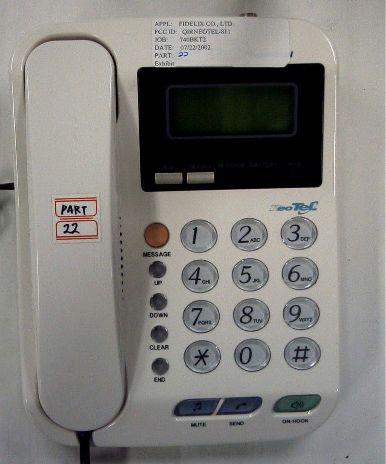
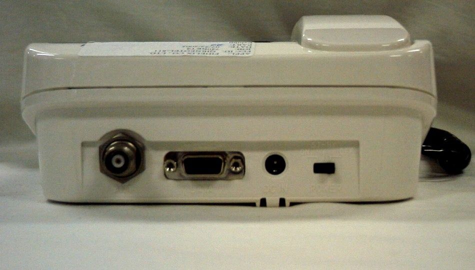
CONTENTS I. Introduction 1. Notice for Using 2. Checking the Package 3. Name and Function of Each Part 4. Installing Terminal II. Preliminary 1. Making Calls 2. To End a Call 3. Redial 4. Receiving Calls 5. Using Memory Functions 1. Storing Numbers In Memory 2. Erasing A Number In Memory 3. One-touch Dialing 4. Two-touch Dialing 5. Redialing For Last Call Numbers 6. Searching For Memories 6. Using Message Functions 1. VMS (Voice Mail Service) 2. Text Message Service 3. Stored Message 4. Message Receiving Time 5. Deleting Message 7. Data Services III. Menu Mode 1. Volume 1. Ringer11 2. Key Beep12 3. Earpiece13 2. Ring Type 3. Alarm 4. Call Information 1. Last Call [41] 2. Home Calls [42] 3. Roam Calls [43] 4. ALL Calls [44] 5. Security 1. Lock mode [51] 2. Restrict [52] 3. Initialize [53] 4. Lock Code [54] 5. Emergency # [55] 6. Clearing calls [56] 6. Features 1. Auto Answer [61] 2. Auto Retry [62] 3. Scratch pad [63] 4. Mute [64] 5. Beep Length [65] 6. One-Touch [66] 7. Display 1. Back light [71] 2. Banner [72] 3. Show Time [73] 4. Auto Hyphen [74] 5. Version [75] 6. New Msg [01] 7. Msg Send [02] 8. Alerts 1. Fade [81] 2. Minute [82] 3. Service [83] 4. Roam Ringer [84] 9. System Data / Fax [94] IV. Appendix V. FWT Technical Specifications I. Introduction Thanks for your purchasing our product. This product is a FWT(Fixed Wireless Terminal) using CDMA(Code Division Multiple Access) technology. Before using this product, please read carefully this chapter. 1. Notice for Using - Do not open the housing of WLL terminal on your own. - Place the terminal in a safe area from shocks. - Do not touch antenna during call. - Avoid hot or moist place. - Do not wipe terminal with chemical solution. - Do not use terminal near to explosives or places where inflammable liquid are used. - When you do not use terminal for long time, switch off and separate Switch Mode Power Supply (SMPS). - Backup battery can be used only when the power is on. 5 2. Checking the Package [Optional Accessories] - External Antenna - - External Antenna Cable - 6 - User's Manual - 3. Name and Function of Each part LCD Screen " Display information about the Terminal status. 4 lines LCD with backlighting. [Menu] Button # Choose function menu and select the left menu in LCD. [RECALL] Button $ Retrieve stored telephone numbers and choose the right menu in LCD. 7 [Menu]Button # " LCD Screen [MESSAGE] ( Button [UP]/[DOWN] ) Button [CLEAR] Button * [END] Button + [MUTE] Button - [SEND] Button . [ON-HOOK] Button / DialButton , RSSI LED ' Battery LED & Message LED % [RECALL] Button $ 8 Message LED: If messages arrive green LED will be lighted. % Battery LED: Colors of LED indicate the remains of Battery power as below. & - Red LED: Indicate that the Battery power is weak. It means, you have to charge the Battery by connecting the external power supply (SMPS). - Yellow LED: Indicate that the Battery power is not sufficient. - Green LED: Indicate that the Battery power is sufficient. RSSI LED: Colors of LED indicate the strength of receiving signal as below. ' - OFF: No service. - Red LED: Indicate that the receiving power is weak. It means, you have to move the terminal to another place or adjusting antenna direction. - Yellow LED: Indicate that the receiving power is not sufficient. - Green LED: Indicate that the receiving power is sufficient. [MESSAGE] Button: Check the received messages. ( [UP]/[DOWN] Button: Retrieve stored telephone numbers, move menu items, ) adjust beep volume and handset loudness. [CLEAR] Button: Clear a character or move to previous menu. * [END] Button: Finish the menu selection. + Dial Button: Input telephone numbers or characters and select menu items. , [MUTE] Button: Make Hold a call for a while. - [SEND] Button: Make a call immediately or make a call to previous number. . [ON-HOOK] Button: Make a call in the on-hook state. / 4 DC In Jack: Connect power supply from SMPS. 4 Power Switch: Make turn on and off the terminal. - ON: Turn on. - ST-BY: Turn off. Terminal turns off with sending "Power off"command to system. - OFF: Turn off. Separate power completely from the internal circuitry. Terminal turns off without sending "Power off" command to system. 4 Data Port: A port which data services are available. 4 Antenna connector: Connector between Di-pole antenna and the terminal 9 DC In Jack Power Switch Data Port Antenna connector 4. Installing Terminal 4 Connect Di-pole antenna to 4Connect handset to the terminal terminal as shown below. (1) as shown below. (2) 4Connect DC jack to the terminal 4Connect the SMPS plug to as shown below. (3) the outlet. (4) (1) (2) (3) (4) 10 4 Turn on the power switch and you can hear the beep sound. 4Check the LCD mode is waiting state or not. 4Adjust direction of Di-pole antenna or move the position of the terminal to improve the strength of receiving radio signal. 11
Cover Letter(s)
To: FCC Equipment Authorization Branch From: Timco Engineering, Inc. September 30, 2002 Re.: FCC Id: QIRNEOTEL-811 Applicant: Fidelix Co., Ltd. Correspondence Number: 5220 Subject: Audit The following is in reply to your inquiries: 1. This device operates in Mobile RF exposure conditions only. The External patch antenna is not part of this filing. The User's Manual was revised and references to the External Antenna were removed. 2. Thank you for your comment about conducted power measurement. The external antenna is not provided with this device. 3. The External patch antenna is not part of this filing. Test setup photos were provided for the dipole antenna only. 4. The External patch antenna is not part of this filing. Sincerely, Bruno Clavier
ID Label/Location Info
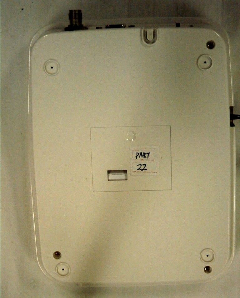
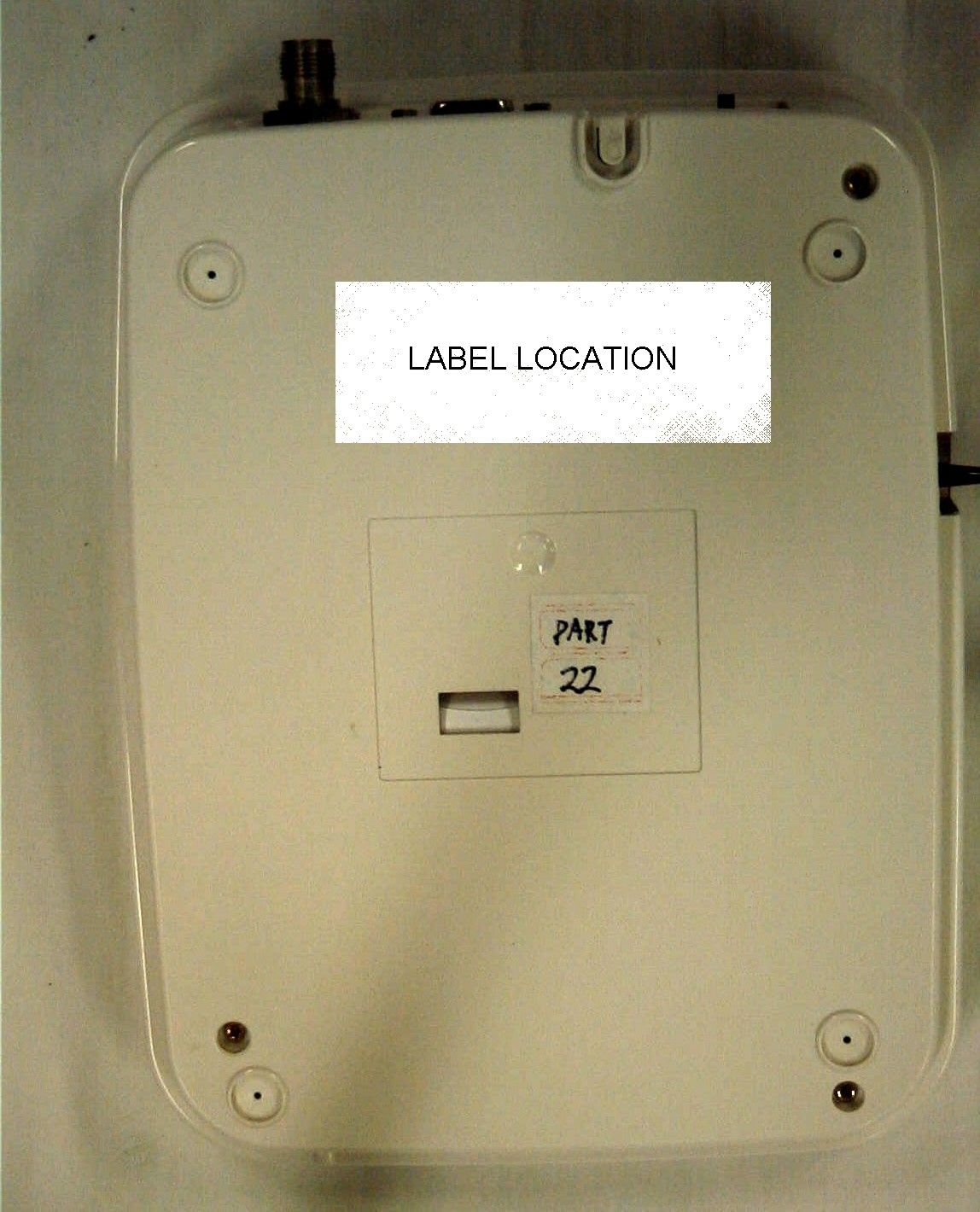
F pioneer from the future communications 4F, Onse Bldg., 192-2, Gumi-Dong, Bundang-Gu Sungnam-Si Kyunggi-Do 463-500 Korea MODEL Name : FxWP-100D MODEL No. : NEOTEL-811 ELECTRICAL RATING DC 9V 1.5A Fidelix FCC ID : QIRNEOTEL-811 This device complies with part 15 of the FCC Rules. Operation is subject to the following two conditions; 1)This device may not cause harmful interference ,and 2)This device must accept any interference received, including interference that may cause undesired operation. FCC RF EXPOSURE REQUIREMENTS In order to satisfy FCC RF exposure requirements for a mobile transmitting device and its antenna should maintain a separation distance 20cm or more from a person's body CAUTION TO PREVENNT ELECTROIC SHOCK, DO NOT REMOVE COVER, NO USER-SERVICEABLE PARTS INSIDE, REFER SERVICING TO QUALIFIED SERVICE PERSONNEL
Operational Description
3.NeoTel-811_circuit_description.DOC 6 / 32 3. Circuit Description In this section, the description for functional blocks of each PBA is explained. Though NeoTel-811 consists of independent PBA’s such as main board, keypad, and sub-key board, PBA’s are connected via various cables with one another. Main board is connected to keypad board with 30-pin FPC cable. Keypad board is connected to LCD module with 16-pin connector, and keypad board is connected to sub-key board with 6-pin cable. Main board adopts a pair of 60-pin connectors to connect with CDMA module. CDMA module consists of two boards, which are CDMA baseband module and RF module. CDMA baseband module and RF module are inter-connected with 60-pin connector. 3.1 Main Board The block diagram of a main board is shown in Figure 3. Each block is explained in the subsequent sections. The speaker phone block is included in the main board, however components are not assembled currently. It can be modified according to the customer’s request. Figure 3. 1. Block Diagram of Main Board. Power Block Serial Communication CDMA Module Interface LCD / Keypad Interface Audio I/O 3.NeoTel-811_circuit_description.DOC 7 / 32 3.1.1 Power Block Figure 3.2. Power Block Diagram of Main Board. The block diagram of a power block is shown in Figure 4. Main board supplies all the power used in NeoTel-811. Main board uses DC 9V/1.5A from SMPS as a main power and 7.2V battery as a backup power. The power block consists of charging circuitry, power on/off circuitry, VPWR, 4V output, 4.6V output, and 3V output. Battery is rechargeable Ni-Cd cells with 7.2V/900mAh capacity. Battery can be replaced to Ni-MH cells with 7.2V/1600mAh in order to enhance time for usage. Battery is continuously charged when the SMPS is plugged in AC voltage regardless of the status of power switch. If failure occurs in the main power from SMPS, the power is changed to backup battery. The power switch has three modes of operation, which are OFF, Powering OFF, and ON. When the power switch is on ON state, PS_CTRL signal from MSM3100 controls terminal to ON state. When the terminal operates with battery, MSM3100 controls PS_CTRL signal to turn out the power of terminal in case of failure of battery power. VPWR is used for circuitry of serial communication with PC. The regulator for 4V output is used for CDMA module. The regulator for 4.6V output is used for audio interface and LCD/LED driving logic. External DC Power (9V DC) Electrical Switch (SI3443) 3V Regulator 5V Regulator 4V Regulator Charge Logic Battery 7.2V Power ON/OFF Logic Power Switch PS_CRTL (From MSM3100) VPWR 3.NeoTel-811_circuit_description.DOC 8 / 32 Finally, the regulator for 3V output is used for power logic driving and serial communication line driving. 3.1.2 LCD / Keypad Interface Figure 3.3. Block Diagram of LCD / Keypad Interface. The block diagram of LCD/Keypad interface is shown in Figure 5. Though LCD/keypad interface has no relation with CDMA module, it controls almost UI (User Interface) functions. LCD/keypad interface consists of 30 signals for keypad, sub-key board and LCD. The signals comprise 10 lines of keypad data, 7 lines of LED drive, 3 lines of LCD drive, and 8 lines of LCD display data. The input power for LCD/keypad interface is 4.6V from 5V regulator in power block of main board. MSM3100 senses key input using key-sense block and GPIO signals. The control signals for LED’s are as follows: two lines for RSSI level, two lines for battery level, and one line for message indication. The LED for RSSI level shows three levels of signal strength such as green, yellow, and red. The LED for battery level also shows three levels of remaining battery level such as green, yellow, and red. The LED for message LCD / Keypad Interface (30 Pin Connector) CDMA Module ( 2X60 Pin Connector ) Keypad [0:9] LCD Data [0:7] LCD Driver Logic LED Driver Logic LCD Data [0:7] LED Lines LED Lines 5 V Regulator Output 3.NeoTel-811_circuit_description.DOC 9 / 32 indication is ON when new message is received. All the LED’s are controlled by LED driver logic on main board. Three lines of LCD driving signal and one line of LCD backlight enable line are directly controlled by MSM3100 through LCD/keypad interface on main board. Eight lines of LCD display data are controlled by LCD driving logic pulled-up to 4.6V on main board. The enable line for LCD backlight can be controlled to ON/OFF by electric switch on keypad board. 3.1.3 Serial Communication : UART, DM Figure 3.4. Block Diagram of Serial Communication Block. The block diagram of serial communication block is shown in Figure 6. The serial communication block provides interface for data communications, which uses UART part inside MSM3100 and some GPIO signals. This block is designed to convert logic signals inside MSM3100 to RS-232 level, which can be connected to PC through RS-232 9-pin connector. RS-232 TX Driver MSM 3100 UART PART DP_TX_DATA RS-232 TX Driver RS-232 TX Driver RS-232 TX Driver RS-232 RX Driver RS-232 RX Driver RS-232 RX Driver DP_RFR DP_CD DP_RI DP_RX_DATA DP_CTS DP_DTR 232_TXD 232_RTS 232_CD 232_RI 232_RXD 232_CTS 232_DTR VPWR 3.NeoTel-811_circuit_description.DOC 10 / 32 3.1.4 Audio Input/Output: Microphone and Earphone Interface, Speaker Phone Interface Figure 3.5. Block Diagram of Audio Input/Output. The block diagram of audio input/output is shown in Figure 7. This block interfaces vocoder block and internal Codec inside MSM3100, which enables the user’s communicating with handset. The audio I/O block interfaces internal Codec inside MSM3100 with microphone and speaker in the handset. The speaker-phone function is implemented in circuitry, however the components are not assembled currently. The speaker- phone function can be provided in case of customer’s request. The RING signal drives buzzer using a ringer signal from DTMF tone generator inside MSM3100. 3.1.5. Keypad, Sub-key and LCD Keypad, Sub-Key LCD PBA module , Main Board . Main Board , Keypad Sub-ke…
Text truncated - open the document above for the full version.
Parts List/Tune Up Info
NeoTel NeoTelNeoTel NeoTel- -- -811 Specification. 811 Specification.811 Specification. 811 Specification. Operating Specifications Operating SpecificationsOperating Specifications Operating Specifications ! IS-95A,B CDMA Protocol Support ! Standard RS-232 Interface ! Air Interface: IS-95B (Tx 824-849 MHz, Rx 869-894 MHz, CDMA only) ! Channel Bandwidth: 1.25 MHz ! Maximum Output Power : Max 250mW [24dBm] ! Voice Coding: IS-96A 8K QCELP(9.6Kbps), IS-125A 13K QCELP(14.4Kbps), PN-3292(IS127) 8K EVRC ! SMS: IS-637 ! Data Service: IS-707A ! OTASP: IS-683 Electrical Specification Electrical SpecificationElectrical Specification Electrical Specification ! Phone AC Power Supply input range : 100 ~ 250VAC, 50/60Hz ! SMPS Output voltage : 9V / 1.5A ! Backup Battery [ Internal Type] # Battery Cell : Ni-Cd # Voltage / Capacity = 7.2V[1.2V * 6cells] / 950mAh Environmental spec. Environmental spec.Environmental spec. Environmental spec. ! Operating temperature : 0 ~ 50 0 C ! Storage temperature : -10 ~ 60 0 C ! Humidity : 5~85 %RH Visual Visual Visual Visual Displ DisplDispl Display ayay ay ! 4-Line Character LCD ! RSSI(Received Signal Strength Indication) [ Green / Yellow / Red ] ! Voice Mail notification [ Green ] ! Battery Status [ Green / Yellow / Red ] Accessory AccessoryAccessory Accessory ! Dipole Antenna ! AC Adaptor [9V/1.5A SMPS] RF Specifications. RF Specifications.RF Specifications. RF Specifications. ! Transmitter Spec Transmitter SpecTransmitter Spec Transmitter Spec Item Description Frequency Range 824.640 – 848.370 MHz Channel Capacity 20 channel Channel Spacing 1.25MHz Tx Power Max 250mW [24dBm] Modulation Technology OQPSK Freq. Accuracy/stability MS reverse carrier Frequency = BS forward carrier Frequency - 45MHz ±300Hz ACPR ± 1.25MHz -45dBC Traffic ρ > 0.944 Range of Open Loop Power Control. Received PWR+Tx PWR = -73dBm$800MHz Maximum RF OutPut Power Ior = -104 dBm/1.23MHz Pilot E…
Text truncated - open the document above for the full version.
Contact Information
Applicant
Seong-Wook Heo(Director)
Test Firm
Timco Engineering, Inc.S Sanders
Technical Specifications
| # | Rule Parts | Frequency Range | Power Output | Emission | Tolerance |
|---|---|---|---|---|---|
| 1 | 22H | 824 MHz - 849 MHz | 250.00 mW | 1M25F9W | 2.5000000000 ppm |
Other Applications from Fidelix Co., Ltd.

QIRFX-N310
Nov 15, 2006Navigation
Equipment Class
JBP - Part 15 Class B Computing Device Peripheral