QJ3IFS-11423Radar Detector
PNI Corporation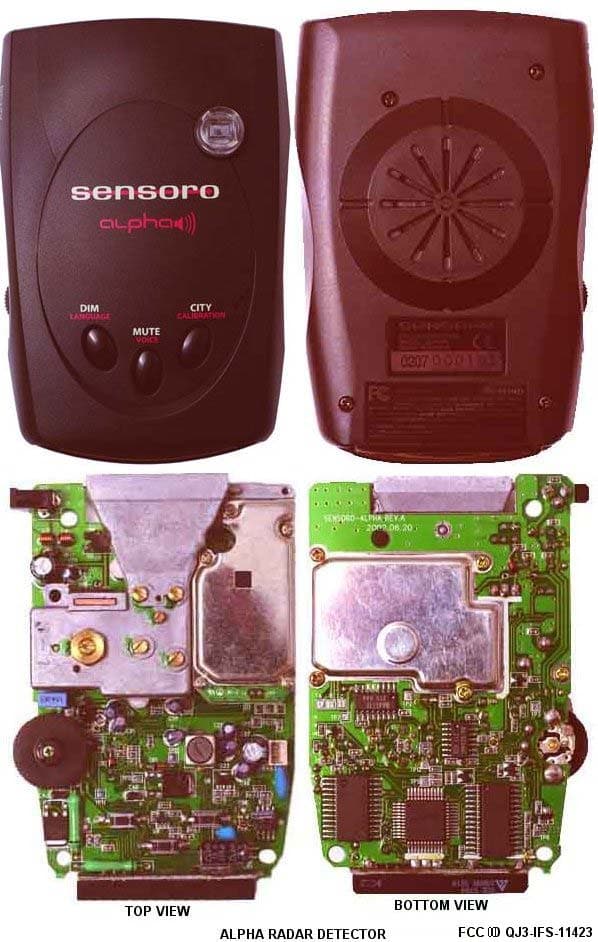
Click to zoom
Application Details
- Equipment Class
- CRD - Part 15 Radar Detector
- Date of Grant
- Sep 19, 2002
- Application Purpose
- Original Equipment
- Date of Application
- Sep 19, 2002
- Equipment Note
- Radar Detector
- Frequency Range
- 10960.00000000 - 11220.00000000
- Company
- PNI Corporation
- Country
- United States
Documents & Files
Document Text
Text extracted from the exhibit documents filed with the FCC. Open a document above to read the original.
Users Manual
OPERATION MANUAL ALPHA/ALPHA+ DIGITALVEHICLECOMPASS &RADAR/LASERDETECTOR Congratulations................................................................1 Features............................................................................1 Package contents...............................................................2 Identifying parts of the unit............................................3 Installing the unit.............................................................4 Mounting guidelines.......................................................4 Windshield mounting.....................................................5 Radar operation................................................................6 Power on..........................................................................6 Functions and modes......................................................6 Invisible to VG-2.............................................................9 Detection alerts...............................................................9 Compass operation.........................................................11 When to calibrate..........................................................11 Calibrating the unit.......................................................11 Compass display............................................................12 Care and maintenance....................................................13 Fuse replacement...........................................................13 Troubleshooting.............................................................14 Specifications..................................................................16 Service and replacement................................................17 Warranty information....................................................19 CONTENTS 1 You have acquired the SENSORO ALPHA/ALPHA+ from PNI Corporation, the first English and Spanish speaking radar/laser detector with a built-in digital compass. The SENSORO ALPHA/ALPHA+ incorporates the same compass technology used in built-in compasses for GM, Ford, and Chrysler vehicles, to provide highly accurate and reliable compass readings in a radar/laser detector. Features • PATENTED DIGITAL COMPASS displays direction information with numeric digits (345°, 350°, etc.) and eight cardinal points (N, NE, E, etc.) • BILINGUAL VOICE WARNING alerts you in English and Spanish • PROTECTION against all radar bands (X, K, and superwide Ka) • 360° LASER COVERAGE protects you against laser guns in all directions • VG-2 protects you by being invisible to radar detector detectors • SAFETY WARNING SYSTEM alerts you to hazard and safety information, including road construction, emergency vehicles, and travel information • TWO SEPARATE CITY MODES (“CITY1” and “CITY2”) in addition to highway mode virtually eliminate false radar alerts • ADDITIONAL CITY MODE (“CITY3”) to delete X-band reports and eliminate most false radar alerts CONGRATULATIONS! 2 • USER SELECTABLE brightness, language, voice on/off, mute on/off, and volume control • TEXT DISPLAY Eight-character text display shows safety warnings, radar alerts, laser alerts, and compass heading • EASY MOUNTING Mounts easily to any windshield • POWER CONNECTION plugs into your 12-volt lighter socket, power cord included Package contents Your SENSORO ALPHA/ALPHA+ package includes the following components: • The SENSORO ALPHA/ALPHA+ digital compass and talking radar/laser detector • Mounting bracket with suction cups for windshield installation • Coiled 12-volt DC power cord • Extra power cord fuse • Operation manual SENSORO ALPHA+ package also includes the following component: • Dual socket 12-volt DC adapter for installation to your vehicle’s fuse panel PACKAGE CONTENTS 3 IDENTIFYING PARTS OF THE UNIT Radar Front Laser Receiver Receiver Power Cord Input Jack DIM/ MUTE/ LED Language Voice Display Button Button Top Laser Receiver CITY/ Calibration Button VOLUME/OFF Control Thumb Wheel 4 Mounting guidelines The SENSORO ALPHA/ALPHA+ can be mounted on your windshield using the bracket provided. • Mount on the windshield in a centered location that will not obstruct the view of the driver and is within reach, so the buttons can be easily accessed. • Do not mount behind windshield wipers, metal surfaces, ornaments, or mirrored sunscreen glass, as these affect radar/laser signals. Tinted glass does not affect radar/laser signal reception. • Do not mount close to strong stereo speakers, as this affects compass accuracy. Conceal the SENSORO ALPHA/ALPHA+ when you leave your vehicle to prevent theft and to minimize the unit’s exposure to extreme temperatures, which can temporarily impair performance. INSTALLING THE UNIT 5 Windshield mounting 1. Install the suction cups onto the windshield mounting bracket by sliding them into their holes (if not pre- installed). 2. Press the bracket base firmly against the windshield until the suction cups securely take hold. 3. Slide the detector into its slot located on the top back of the detector. Dashboard Windshield 4. Bend the angle of the windshield mounting bracket, if necessary, to adjust for best viewing and detection angle. 5. Plug the small connector of the power cord into the 12-volt DC power input jack located on the side of the detector. 6. Plug the lighter adapter into the lighter socket. INSTALLING THE UNIT 6 Power on Turn the VOLUME/OFF thumb wheel control on. The SENSORO ALPHA/ALPHA+ goes through a self test pattern sequence and displays the last mode previously set in memory. Functions and modes Volume/on/off Use the VOLUME/OFF thumb wheel, located on the side of the SENSORO ALPHA/ALPHA+, to turn the unit on or off or to adjust volume level. Dim mode Press the DIM button repeatedly for less than two seconds each time to toggle between the four levels of brightness modes. Dim mode reduces the brightness of the display. When a signal is detected, alerts are displayed in full brightness, regardless of dim mode. Then the display retu…
Text truncated - open the document above for the full version.
ID Label/Location Info
PNI Corp. Engineering Group J Miller 8/28/2002 Doc 1000437 Rev R01 Description of FCC Labeling For Alpha Radar Detectors For FCC Part 15 Order FCC02-211 compliance. PNI FCC file for FCC License QJ3-IFS-11423 Purpose This document describes the discrete models and marketing names used under the FCC license QJ3-IFS-11423. Additionally this document describes the placement of the FCC ID label and notifications placed on the product and in the user manuals. Procedure 08/28/2002 PNI Corp part number 11423 will use the marketing name Alpha. The FCC ID label will appear as shown in figure 1 below. Figure 2 shows the placement of the label on the bottom of the unit, while Figure 3 shows the FCC license information used in the manual on the first production run in September of 2002. The device in the Alpha + (plus) marketed package will have the exact same circuitry as the Alpha unit. The Alpha + contains extra user accessories external to the function of the device. The Alpha + is a future product and as such does not currently have a PNI Corp. part number. Figure 1 Label to be applied directly on product Description of FCC labeling for Alpha Radar Detectors (REPORT - 1000437 - R01).DOC Page 1 of 3 PNI Corp. Engineering Group J Miller 8/28/2002 Doc 1000437 Rev R01 Figure 2 Placement of label on bottom of unit Description of FCC labeling for Alpha Radar Detectors (REPORT - 1000437 - R01).DOC Page 2 of 3 PNI Corp. Engineering Group J Miller 8/28/2002 Doc 1000437 Rev R01 Description of FCC labeling for Alpha Radar Detectors (REPORT - 1000437 - R01).DOC Page 3 of 3 Figure 3 label used in user manual
Operational Description
PNI Corp. Engineering Group J Miller 8/28/2002 Doc 1000438 Rev R01 Theory of Operation Alpha Radar Detector For FCC Part 15 Order FCC02-211 compliance. PNI FCC file for FCC Lincense QJ3-IFS-11423 The Alpha line of radar detectors are two-stage superheterodyne receivers that detect the presence of speed measuring radar in the X, K and Ka bands. The local oscillator frequency in the first mixing stage is swept from 10.92 GHz to 11.39 GHz. In the second mixing stage there are three discrete frequencies used for the local oscillator. These are turned on in succession, one frequency per 1 st local oscillator sweep period. The second local oscillator frequencies are 530MHz, 1550MHz and 2085MHz. An LED display shows band and signal level detection status. Theory of operation Alpha Radar Detectors (REPORT - 1000438 - R01).DOC Page 1 of 1
Test Report
REPORT OF TEST DATA FOR FOR PNI Prepared by Daniel C. Swann August 26, 2002 Alpha and Traveler Radar Detectors GEL File PNI 01-2002 GLEN ELLEN LABORATORIES 1876 London Ranch Road Glen Ellen, CA 95442 GEL File PNI 01-2002 Glen Ellen Laboratories 2August 26, 2002 TABLE OF CONTENTS 1.Test Methodology 2.Description of Test Facility, including information on calibration as presented in Glen Ellen Laboratories FCC, CISPR and Bellcore test reports. 3.Photographs of test configuration, including front and rear views of tested configuration of both units. 3.Radiated Emissions Data 3.1Unintentional Radiated Emissions, Traveler, 12 Volt power, in band 11.7 to 12.2 GHz 3.2Unintentional Radiated Emissions, Traveler, battery power, in band 11.7 to 12.2 GHz 3.2Unintentional Radiated Emissions, Alpha, in band 11.7 to 12.2 GHz 3.3Field Strength Calculation for Radiated Emissions 4.0Photographs of Tested Units GEL File PNI 01-2002 Glen Ellen Laboratories 3August 26, 2002 1.Test Methodology The radiated tests were performed in accordance with the procedures specified by ANSI C63.4-2001. Compliance with applicable standards was determined by comparing the measured results with respect to the limits specified in rulemaking FCC 02-211. Measurements were made at 1 meter distance, as allowed by 47CFR Section 15.31(f)(1). The limit for the 1 meter measurement was calculated using an inverse linear distance extrapolation faction (20 dB/decade), Limit 1 meter = Limit 3 meters + 20*LOG(3/1) or Limit 1 meter = Limit 3 meters + 9.5 dB The test procedure used was the following: 1)Determine the frequency of the peak emission: Start Frequency11.7 GHz Stop Frequency12.2 GHz RBWEqual to or greater than 1 MHz VBWEqual to or greater than 1 MHz Detector FunctionPeak Maximize the emissions with regards to device orientation, antenna polarization, and antenna height. Sweep the band using Max Hold for a minimum of 2 minutes. Record this frequency for measuring the peak emission. In addition record the frequency of other spurious emissions noted. 2)Determine the peak level of the emission: Center FrequencySet to the frequency determined in Step 1 RBWEqual to or greater than 1 MHz VBWEqual to or greater than 1 MHz Detector FunctionPeak GEL File PNI 01-2002 Glen Ellen Laboratories 4August 26, 2002 Measure the value of the peak emission using Max Hold for a minimum of 2 minutes. This can be done at zero span or a frequency span where the analyzer does not show a “Measurement Uncalibrated” message. Record the peak value. If the peak measurement is compliant with the average limit an average measurement is not necessary. If the peak value exceeds the average limit by less than 20 dB proceed to Step 3. 3)Determine the average level of the emission: Center FrequencySet to the frequency determined in Step 1 SpanZero RBWEqual to or greater than 1 MHz VBWEqual to or greater than 10 Hz Detector FunctionPeak This measurement uses video averaging and must be done in Linear mode. The analyzer Reference Level will have to be adjusted so that a signal is clearly visible on the screen. Measure the value of the emission using Max Hold for a minimum of 2 minutes. Record this as the average value. Step 2 and Step 3 was repeated for other spurious emissions within the band. GEL File PNI 01-2002 Glen Ellen Laboratories 5August 26, 2002 2.Description of Test Facility, including information on calibration as presented in Glen Ellen Laboratories FCC, CISPR and Bellcore test reports. The Glen Ellen Laboratories open field test site complies with the requirements specified by VDE 0876/9.78, VDE 0877 Part 1/11.81, VDE 0877 Part 2/2.85, CISPR 16, CISPR 22, and ANSI C63.4- 2001. The test site closely follows the theoretical normalized site attenuation specifications for both horizontal and vertical polarizations. The site has been fully described in a report dated September 30, 1999, submitted to the FCC, and accepted in a letter dated December 15, 1999 (Registration Number 90613.) The facility is located near the town of Glen Ellen, California, at the street address of 1876 London Ranch Road. The site is at approximately 175 meters altitude on the East side of Sonoma Mountain, at the coordinates of 38 degrees 22 minutes North Latitude and 122 degrees 32 minutes West Longitude. The site sits north of a ridge approximately 100 meters higher in elevation and 1000 meters to the South, which attenuates VHF and above frequencies from the San Francisco Bay area 60 kilometers to the South. The open field test site consists of a 10 by 20 meter area of galvanized hardware cloth placed on top of a flat asphalt surface located in an open meadow. All seams of adjacent widths of hardware cloth are soldered together. The metal turntable top surface is flush with the ground plane. All metal objects other than the groundscreen/flush turntable are located a considerable distance further than the standard 10-meter CISPR measurement ellipse. Test Equipment List Test equipment used included: 1.Hewlett Packard 8591EM spectrum analyzer, cal due 06-20-03. 2.Hewlett Packard 8566 opt L24 spectrum analyzer, cal due 06-20-03. 3.GEL AP2-10 preamplifier, 2 GHz to 10 GHz, cal due 7-20-03. 4.ETS Horn Antenna, 1 GHz to 18 GHz, cal due 7-29-03. GEL File PNI 01-2002 Glen Ellen Laboratories 6August 26, 2002 3.1Unintentional Radiated Emissions, Traveler, 12 Volt power, in band 11.7 to 12.2 GHz Test Personnel: Tester SignatureDate August 26, 2002 Tester NameDaniel C. Swann GEL File PNI 01-2002 Glen Ellen Laboratories 7August 26, 2002 3.1Unintentional Radiated Emissions, Traveler, 12 Volt power, in band 11.7 to 12.2 GHz (continued) 1 meterHorn1 meter3 meter Frequency Corrected Antenna Cable AmplifierFieldFCCFCCField MHzMeasuredFactorLossGainStrengthLimitMarginStrength AmplitudedB/mdBdBdBuV/mdBuV/mdBuV/m dBuV20 dB added Vertical Polarization 20 dB Peak Level Check Traveler 2, with 12 Volt power car adapter 11709.00044.239.51.216.468.483.5-15.1832.8 corrected 1 meterHorn1 meter3 meter Frequency Co…
Text truncated - open the document above for the full version.
Test Setup Photos
GEL File PNI 01-2002 Glen Ellen Laboratories 13August 26, 2002 4PHOTOGRAPHS View of Front of Radiated Test Setup, Traveler 2, with 12 Volt adapter GEL File PNI 01-2002 Glen Ellen Laboratories 14August 26, 2002 View of Rear of Radiated Test Setup, Traveler 2, with 12 Volt adapter GEL File PNI 01-2002 Glen Ellen Laboratories 15August 26, 2002 View of Front of Radiated Test Setup, Traveler 2, battery powered GEL File PNI 01-2002 Glen Ellen Laboratories 16August 26, 2002 View of Rear of Radiated Test Setup, Traveler 2, battery powered GEL File PNI 01-2002 Glen Ellen Laboratories 17August 26, 2002 View of Rear of Radiated Test Setup, Alpha GEL File PNI 01-2002 Glen Ellen Laboratories 18August 26, 2002 View of Rear of Radiated Test Setup, Alpha
Contact Information
Applicant
George Hsu(Chairman & CEO)
Test Firm
Glen Ellen LaboratoriesDaniel Swann
Technical Specifications
| # | Rule Parts | Frequency Range | Power Output |
|---|---|---|---|
| 1 | 15B | 10.96 GHz - 11.22 GHz | - |
Other Applications from PNI Corporation

QJ3-12579
Oct 26, 2005Radar Detector
Equipment Class
CRD - Part 15 Radar Detector
QJ3-12565
Jun 15, 2005Radar Detector
Equipment Class
CRD - Part 15 Radar Detector
QJ3-IFS-12418
Dec 20, 2004Radar Detector
Equipment Class
CRD - Part 15 Radar Detector
QJ3-IFS-12173
Jun 14, 2004Compass System with Wireless Temperature Sensor
Equipment Class
DXX - Part 15 Low Power Communication Device Transmitter
QJ3-IFS-11875
Apr 07, 2004Radar Detector
Equipment Class
CRD - Part 15 Radar Detector