QJ7-JLM051690WIRELESS LAN
Communications Development LLC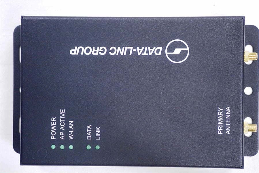
Click to zoom
Application Details
- Equipment Class
- DTS - Digital Transmission System
- Date of Grant
- Feb 16, 2004
- Application Purpose
- Original Equipment
- Date of Application
- Feb 16, 2004
- Equipment Note
- WIRELESS LAN
- Frequency Range
- 2412.00000000 - 2462.00000000
- Country
- United States
Documents & Files
Document Text
Text extracted from the exhibit documents filed with the FCC. Open a document above to read the original.
Users Manual
I NDUSTRIAL W IRELESS E THERNET M ODEM FLC810E FOR THE 2.4TO 2.4835 GHZ ISM BAND FEATURES • • • • • Provides high-speed wireless Ethernet connectivity using the 2.4-2.483 license-free spread spectrum band • • • • • High output power and excellent receiver sensitivity for outstanding in-plant RF coverage and outdoor range • • • • • Rated range of 5 miles with unobstructed line-of- sight (farther using repeaters and/or higher gain antennas) • • • • • Coexists with Data-Linc’s Smart Spectrum ™ SRM6210E frequency hopping technology for hybrid 900 MHz and 2.4 GHz RF SCADA systems • • • • • Wireless connections to PLCs, HMIs, Ethernet I/O systems and portable computers • • • • • Compatible with WiFi and IEEE 802.11b compliant devices • • • • • Functions as a wireless access point, wireless bridge or remote repeater • • • • • Supports point-to-point, point-to-multipoint and peer- to-peer topologies • • • • • Compact, flexible design with universal mounting including an optional DIN rail connector • • • • • Web page (HTML) configuration and diagnostics • • • • • Built-in data encryption and authentication for added security • • • • • Factory or field configured for your application for trouble-free installation • • • • • AC or DC powered FastLinc TM Industrial Ethernet Wireless Modems are a high-speed, secure wireless solution using 2.4 GHz direct sequence technology. They are available in stand-alone Ethernet (FLC810E) and PCMCIA card (FLC800C) models. FastLinc modems have a rated range of 5 miles with unobstructed line-of-sight, farther using repeaters and/or higher gain antennas. With an output power much higher than commercial IEEE 802.11b products, they provide longer outdoor range and broader indoor coverage. The FLC810E includes wireless bridge mode for linking remote plant networks, access point mode for creating wireless hotspots within industrial plants and wireless connections between PLCs, HMIs, and Ethernet I/O systems. It can be configured as a wireless bridge repeater to extend range and overcome line-of-sight (LOS) obstructions. The high power FLC800C (PCMCIA card) allows for network communications of portable computers with a robust wireless connection. FastLinc modems can coexist with Data-Linc’s popular Smart Spectrum TM frequency hopping technology, permitting both high-speed and long range wireless networks ideally suited for utility SCADA systems. The modems are easy to configure and trouble shoot with built-in diagnostics using a web-based interface. As with all Data-Linc products, support services such as pre-sale project consultation, post-sale tech support with PLC expertise and site survey planning assistance are part of the Data-Linc Group commitment. • Connect remote plant networks without monthly phone line charges • Wireless SCADA communications for pump stations, well heads, pipelines, storage tanks, etc. • Wireless Ethernet I/O to moving equipment (over head cranes, transfer cars, turntables, etc.) • Portable computer communications for mobile HMIs and maintenance stations • Wireless hotspots in industrial plants APPLICATIONS
Users Manual
FastLinc 810E manual Rev 3 F F a a s s t t L L i i n n c c 8 8 1 1 0 0 E E I I n n d d u u s s t t r r i i a a l l W W i i r r e e l l e e s s s s E E t t h h e e r r n n e e t t M M o o d d e e m m FCC Information This device complies with Part 15 of the FCC Rules. Operation is subject to the following two conditions: (1) this device may not cause harmful interference, and (2) this device must accept any interference received; including interference that may cause undesired operation. Federal Communications Commission (FCC) Statement This Equipment has been tested and found to comply with the limits for a Class B digital device, pursuant to Part 15 of the FCC rules. These limits are designed to provide reasonable protection against harmful interference in a residential installation. This equipment generates, uses and can radiate radio frequency energy and, if not installed and used in accordance with the instructions, may cause harmful interference to radio communications. However, there is no guarantee that interference will not occur in a particular installation. If this equipment does cause harmful interference to radio or television reception, which can be determined by turning the equipment off and on, the user is encouraged to try to correct the interference by one or more of the following measures: - Reorient or relocate the receiving antenna. - Increase the separation between the equipment and receiver. - Connect the equipment into an outlet on a circuit different from that to which the receiver is connected. -Consult the dealer or an experienced radio/TV technician for help. FCC RF Radiation Exposure Statement: 1. This Transmitter must not be co-located or operating in conjunction with any other antenna or transmitter. 2. This equipment complies with FCC RF radiation exposure limits set forth for an uncontrolled environment. This equipment should be installed and operated with a minimum distance of 20 centimeters between the radiator and your body. The only antennas to be used with this device are as follows: • Supplied whip antenna • 2 dB omni manufacture # MHWS2400MSMARP • 5 dB omni manufacture # MAXC24505 • 6 dB omni manufacture # MFB2406 • 8 dB omni manufacture # MFB2408 (with a 2 dB attenuation restriction) • 10 dB yagi manufacture # MYP24010PT • 14 dB yagi manufacture # MYP24014PT (with a 3 dB attenuation restriction) • 14 dB yagi manufacture # PC2415N (with a 3 dB attenuation restriction) Professional installation of this product is required. Table of Contents Chapter 1 Introduction ......................................................................1 1-1 Features and Benefits ................................................................................... 1 1-3 System Configurations.................................................................................. 2 Chapter 2 Hardware Installation ......................................................3 2-1 Product Kit ................................................................................................... 3 2-2 System Requirements .................................................................................... 3 2-3 Mechanical Description ............................................................................... 4 2-4 Hardware Installation .................................................................................. 5 Chapter 3 Configuring the FastLinc 810E Modem ............................6 3-1 Using the FastLinc 810E Modem Utility ..................................................... 6 3-2 Using the Web Management ...................................................................... 18 3-3 Using the Telnet.......................................................................................... 23 Chapter 4 Troubleshooting.................................................................30 Appendix A Network Configuration .................................................32 A-1 Network Topology ...................................................................................... 32 Appendix B Specifications ...............................................................35 Appendix C Glossary ..........................................................................36 Chapter 1 Introduction The FastLinc 810E Industrial Wireless Ethernet Modem is specially designed for Point-to-Point and Point-to-Multipoint wireless applications, offering system-wide connections between PLC’s at a speed of up to 11Mbps over the air data rate. Fully compliant with IEEE802.11b standard, the FastLinc 810E Modem provides powerful features such as the Windows-based configuration utility, MAC address filtering, WEP security and more. 1-1 Features and Benefits Creates a Point-to-Point connection linking two LANs, using 2 FastLinc 810E Modems. Creates a Point-to-Multipoint system using three or more FastLinc 810E Modems. External antenna allows for the use high gain antennas. With an over the air data rate of 11Mbps and 5.5Mbps, the system is faster than an E1/T1 data link. Fully IEEE 802.11b compatible. Transmits in the unlicensed 2.4Ghz ISM band. Seamless roaming within the 802.11 & 802.11b wireless LAN infrastructure. Provides user authentication to enforce tight security. MAC address control for enhanced security Easy to install and configure. Provides Window-based configuration utility. Industrial rugged-ized enclosure provides protection in harsh environments. -1- 1-3 System Configurations The FastLinc 810E Industrial Wireless Ethernet Modem can be configured in a variety of network system configurations. Wireless Infrastructure In a wireless infrastructure, the FastLinc 810E Modem acts as a bridge. The FastLinc 810E Modem connects the wireless clients together. The FastLinc 810E Modem acts as a center point for all wireless communications. This would increase efficiency of the communications since the wireless adapters do not need to be within direct range of each other. FastLinc 810E…
Text truncated - open the document above for the full version.
Users Manual
3-2 Using the Web Management The built-in Web Management provides you with a user-friendly graphical user interface (web pages) to manage your FastLinc 810Es. An AP with an assigned IP address (the default address is 192.168.1.1) will allow you via web browser (e.g., Netscape Navigator 3.0 ~ 4.5 or MS Internet Explorer 4.0) to monitor and configure the FastLinc 810E. 1. Open your web browser. 2. Enter the IP address of your FastLinc 810E in the Address field (the default address is 192.168.1.1). You will have access to the FastLinc 810E Web Pages of the FastLinc 810E Modem. 3. Enter the password to login to the FastLinc 810E. The default password is default. The main page will show up. -18- The FastLinc 810E main page contains two items for you to manage your FastLinc 810E Modem. Information General This item displays the general information of the FastLinc 810E such as the MAC address, Frequency Domain, and Firmware Version. -19- Statistics This item displays the Ethernet and wireless network traffic. Configuration General You may make the settings on the FastLinc 810E such as AP mode, ESSID, channel, RTS threshold, fragment threshold and password. -20- WEP To prevent unauthorized wireless stations from accessing data transmitted over the network, the FastLinc 810E Modem offers WEP (Wired Equivalency Privacy). You can set up 4 encryption keys but choose one key to encrypt your data. Access Control The Access Control Table enables you to restrict wireless stations accessing the FastLinc 810Es by identifying the MAC address of the wireless devices. -21- Upgrade Here, you can upload the newest firmware of the FastLinc 810E. You may either enter the file name in the entry field or browse the file by clicking the Browse button. -22- 3-3 Using the Telnet The FastLinc 810E can be configured via the command prompt console with TCP/IP: Telnet (TCP/IP) Connection: Assign an IP address to your FastLinc 810E through the Modem Utility or use the default IP address. Telnet to the FastLinc 810E to get access to the FastLinc 810E console using standard Telnet commands. 1. Telnet to your FastLinc 810E. A window will show up. 2. Enter the password. The default password is “default”. 3-2-1 Basic Commands The following are the commands provided for configuring the FastLinc 810E. In loader mode, i.e., no valid firmware in the FastLinc 810E, only the commands with an asterisk (*) are provided. NOTE: [xxx] stands for optional arguments. -23- info * Display some basic information of the FastLinc 810E, for example, firmware version, frequency domain, etc. stat Display the statistical values of the operation of the FastLinc 810E, for example, association status, LAN/WLAN interface load, etc. -24- ping ip_addr [num_pings] [data_size] Ping (ICMP echo) to an ip_addr host with optional num_pings times with optional data size in a length of data_size. set List the configuration information. set apname | channel | essid | rts_threshold | frag_threshold | ip_address | ip_netmask | ip_gateway -25- To change factory default settings, type “set xxx (parameter) xxxx (value). For example, set channel 7 command will set the channel to number 7; set essid “Your Network” command will set the ESSID as Your Network. Remember that, a 'save' command is required for changes to take effect. Always reset your AP with the “Reset” command. The following is a list of parameters you can make changes on the FastLinc 810E. Parameter Description Default Value apname A textual name for the identification of the FastLinc 810E. apXXXXXX (where XXXXXX is the last six octets of FastLinc 810E’s MAC address) mode Operation mode of the Modem AP channel The radio channel number. 1 essid The ESS ID (a.k.a., SSID) of the FastLinc 810E. My Network rts_threshold The threshold (number of bytes) for enabling RTS/CTS handshake. Data with its frame size larger than this value will perform the RTS/CTS handshake. Range of value: 0~2432. 2432 frag_threshold The threshold (number of bytes) for the fragmentation boundary. Data will be transmitted in fragments which its size does not exceed this value. Range of value: 256~2432. 2432 ip_address The IP address of the FastLinc 810E. 192.168.1.1 ip_netmask The subnet mask address of the FastLinc 810E. 255.255.255.0 ip_gateway The default gateway address of the FastLinc 810E. 192.168.1.254 -26- save Save your new configuration. Remember that the “save command” is required every time you make the new configuration. set default Return the factory default settings of the FastLinc 810E except for the IP addresses. A 'save' command is required for changes to take effect. cls * Clear the console screen. exit * Exit the console. ? * or help * Print a help screen. rz * Receive a firmware file by the Zmodem protocol. The console will enter Zmodem receiving mode and then use the "file upload" function of your terminal emulation program to upload a new firmware file (ap.img) to the FastLinc 810E. Upon completion, always remember to type the 'reset' command for running the FastLinc 810E with the new firmware. reset * Issue a reset signal. The FastLinc 810E will be reset if user confirms. 3-2-2 Advanced Settings for Security This section describes the commands to control the security for FastLinc 810E. To prevent unauthorized wireless stations from accessing data transmitted over the network, the FastLinc 810E Modem offers the following levels of security options. - Access Control Table restricts wireless stations to access the FastLinc 810E. - Data Encryption, known as WEP (Wired Equivalency Privacy), encrypts wireless data transmitted via wireless medium. Access Control auth mode | add | del | list| clear The 'auth' command contains sub-commands that allow you to manage the access control (MAC address filter) of the FastLinc 810E. The access control table consists of a list for you to control the accessibility of any wireless stations or repeaters. The sub-commands are listed below: mode open | allow: set the access control mode…
Text truncated - open the document above for the full version.
Cover Letter(s)
Communications Development LLC October 3, 2003 Federal Communications Commission 7435 Oakland Mills Road Columbia, MD 21046 USA Dear Sir or Madam: Subject: Request of Confidentiality Pursuant to Sections 0.457(d)(1)(ii) and 0.459 of the Commission’s Rules, the applicant hereby request the confidential treatment of the following; Schematics, Theory of Operations and Block Diagram This information is confidential and contains trade secretes as well as proprietary information. The public discloser of the above information could be harmful to the applicant and would provide information to its competitors that could be used against them in the market place in which they compete. Sincerely, Randy Maes
External Photos
Wireless PC card external photos Top of card Bottom of card Antenna connector end of card PCMCIA connector end of card
ID Label/Location Info
QJ7-JLM051690 Label location Bottom of card
ID Label/Location Info
FastLinc Wireless Lan PC Card FCC ID: QJ7-JLM051690 MADE IN TAIWAN This device complies with Part 15 of FCC Rules. Operation is Subject to the following conditions: (1) this device may not cause harmful interference. and (2) this device must accept any interference that may cause undesired operation. Model: FLC800C FC C !
Internal Photos
Covers Off, Showing Shields In Place Disassembled (Some Shields Removed) PCB Top (Some Shields Removed) Top, All Shields Removed PCB Bottom View
Test Report
TIMCO ENGINEERING INC. 849 NW State Road 45 Newberry, Florida 32669 http://www.timcoengr.com 888.472.2424 F 352.472.2030 email: [email protected] APPLICANT: COMMUNICATIONS DEVELOPMENT LLC FCC ID: QJ7-JLM051690 REPORT #: D\DataLinc_\1418GUT3\1418GUT3TestReport.doc COVER SHEET Test Report Product Name: WIRELESS LAN FCC ID: QJ7-JLM051690 Applicant: COMMUNICATIONS DEVELOPMENT LLC 2003 WESTERN AVENUE Suite 400 SEATTLE, WA 98121 Date Receipt: JANUARY 9, 2004 Date Tested: FEBRUARY 13, 2004 TIMCO ENGINEERING INC. 849 NW State Road 45 Newberry, Florida 32669 http://www.timcoengr.com 888.472.2424 F 352.472.2030 email: [email protected] APPLICANT: COMMUNICATIONS DEVELOPMENT LLC FCC ID: QJ7-JLM51690 REPORT #: D\DataLinc_\1418GUT3\1418GUT3TestReport.doc TABLE OF CONTENTS TABLE OF CONTENTS FOR A DIRECT SEQUENCE SPREAD SPECTRUM TEST REPORT CONTAINING: PAGE 1.............LETTER OF EXPLANATION PAGE 2.............LIST OF TEST EQUIPMENT PAGE 3.............TEST PROCEDURES PAGE 4.............POWERLINE CONDUCTED INTERFERENCE PAGE 5-6...........POWERLINE CONDUCTED PLOTS PAGE 7.............OCCUPIED BANDWIDTH AND POWER OUTPUT PAGE 8.............6 dB BANDWIDTH PLOTS PAGE 9.............SPURIOUS EMISSIONS AT ANTENNA TERMINALS DATA METHOD OF MEASURING RF CONDUCTED AND PAGE 10-11.........RADIATION INTERFERENCE TEST DATA PAGE 12............METHOD OF MEASURING RADIATED SPURIOUS EMISSIONS PAGE 13-28.........RADIATED SPURIOUS EMISSIONS INTO ADJACENT RESTRICTED BANDS PAGE 29............POWER SPECTRAL DENSITY PAGE 30............POWER SPECTRAL DENSITY PLOTS PAGE 31............MPE CALCULATION & CONCLUSION EXHIBIT INCLUDED: REQUEST FOR CONFIDENTIALITY LETTER BLOCK DIAGRAM SCHEMATICS USERS MANUAL LABEL SAMPLE LABEL LOCATION EXTERNAL PHOTOGRAPHS INTERNAL PHOTOGRAPHS OPERATIONAL DESCRIPTION TEST SET UP PHOTOGRAPHS TIMCO ENGINEERING INC. 849 NW State Road 45 Newberry, Florida 32669 http://www.timcoengr.com 888.472.2424 F 352.472.2030 email: [email protected] APPLICANT: COMMUNICATIONS DEVELOPMENT LLC FCC ID: QJ7-JLM051690 REPORT #: D\DataLinc_\1418GUT3\1418GUT3TestReport.doc Page 1 of 31 FEBRUARY 13, 2004 Federal Communications Commission Authorization and Evaluation Division 7435 Oakland Mills Road Columbia, MD 21046 SUBJECT: COMMUNICATIONS DEVELOPMENT LLC FCC ID: QJ7-JLM051690 To Whom It May Concern: The attached application is for a direct sequence spread spectrum assembly, made up of the Bridge/Radio , and several antennas and coaxial cable (3 dB of loss). COMMUNICATIONS DEVELOPMENT LLC purchases standard antennas from their manufacturers. The radio uses a unique connector a reverse SMA. COMMUNICATIONS DEVELOPTMENT LLC equipment is only professionally installed. Antennas Tested: Cushcraft PC-2415 (13.9 dBi yagi) Maxrad MFB2408 (8 dBi omni) Maxrad MYP24014PTNF (14 dBi yagi) Maxrad MHWS2400MSMARP (2 dBi omni) We are including with this application omni directional antennas from the same manufacturer. These are of the same construction as tested but with lower gains than the ones tested Should you have any questions or require any further information with regards to this, please feel free to contact me. Sincerely, Mario R. de Aranzeta C.E.T. MRD/sh Encl. TIMCO ENGINEERING INC. 849 NW State Road 45 Newberry, Florida 32669 http://www.timcoengr.com 888.472.2424 F 352.472.2030 email: [email protected] APPLICANT: COMMUNICATIONS DEVELOPMENT LLC FCC ID: QJ7-JLM051690 REPORT #: D\DataLinc_\1418GUT3\1418GUT3TestReport.doc Page 2 of 31 EMC Equipment List Device Manufacturer Model Serial Number Cal/Char Date Due Date 3/10-Meter OATS TEI N/A N/A Listed 3/26/01 3/26/04 3-Meter OATS TEI N/A N/A Listed 1/13/03 1/13/06 Biconnical Antenna Eaton 94455-1 1057 CAL 3/18/03 3/18/05 Biconnical Antenna Eaton 94455-1 1096 CAL 10/1/01 10/1/03 Biconnical Antenna Electro- Metrics BIA-25 1171 CAL 4/26/01 4/26/03 Double- Ridged Horn Antenna Electro- Metrics RGA-180 2319 CAL 2/17/03 2/17/05 LISN Electro- Metrics ANS-25/2 2604 CAL 10/9/01 10/9/03 LISN Electro- Metrics EM-7820 2682 CAL 3/12/03 3/12/05 Log- Periodic Antenna Eaton 96005 1243 CAL 5/8/03 5/8/05 TIMCO ENGINEERING INC. 849 NW State Road 45 Newberry, Florida 32669 http://www.timcoengr.com 888.472.2424 F 352.472.2030 email: [email protected] APPLICANT: COMMUNICATIONS DEVELOPMENT LLC FCC ID: QJ7-JLM051690 REPORT #: D\DataLinc_\1418GUT3\1418GUT3TestReport.doc Page 3 of 31 TEST PROCEDURE GENERAL: This report shall NOT be reproduced except in full without the written approval of TIMCO ENGINEERING, INC. POWER LINE CONDUCTED INTERFERENCE: The procedure used was ANSI STANDARD C63.4- 2000 using a 50 uH LISN. Both lines were observed with the UUT transmitting. The bandwidth of the spectrum analyzer was 10kHz with an appropriate sweep speed. The ambient temperature of the UUT was 76°F with a humidity of 55%. BANDWIDTH 6.0 dB: The measurements were made with the spectrum analyzer's resolution bandwidth (RBW)=1.0 MHz and the video bandwidth (VBW) =1.0 MHz and the span set as shown on plot. POWER OUTPUT: The RF power output was measured at the antenna feed point using a peak power meter. ANTENNA CONDUCTED EMISSIONS: The RBW=100 kHz, VBW=300 kHz and the span set to 10.0MHz and the spectrum was scanned from 30 MHz to the 10 th Harmonic of the fundamental. Above 1.0 GHz the resolution bandwidth was 1.0MHz and the VBW = 3.0MHz and the span set to 50 MHz. RADIATION INTERFERENCE: The test procedure used was ANSI STANDARD C63.4-2000 using a HEWLETT PACKARD spectrum analyzer with a pre-selector. The bandwidth (RBW) of the spectrum analyzer was 100 kHz up to 1 GHz and 1 MHz above 1 GHz with an appropriate sweep speed. The VBW above 1 GHz was = 3 MHz. The analyzer was calibrated in dB above a microvolt at the output of the antenna. The ambient temperature of the UUT was 53°F with a humidity of 17%. TIMCO ENGINEERING INC. 849 NW State Road 45 Newberry, Florida 32669 http://www.timcoengr.com 888.472.2424 F 352.472.2030 email: [email protected] APPLICANT: COMMUNICATIONS DEVELOPMENT LLC FCC ID: QJ7-JLM051690 REPORT #: D\DataLinc_…
Text truncated - open the document above for the full version.
Contact Information
Applicant
Jamie Stubner(Registered Agent)
Test Firm
Timco Engineering, Inc.S Sanders
Technical Specifications
| # | Rule Parts | Frequency Range | Power Output |
|---|---|---|---|
| 1 | 15C | 2.41 GHz - 2.46 GHz | 158.00 mW |
Other Applications from Communications Development LLC
QJ7-JNM032189
Dec 05, 2002902-928 MHz Radio with Antennas
Equipment Class
DSS - Part 15 Spread Spectrum Transmitter