QJ7-JNM032189902-928 MHz Radio with Antennas
Communications Development LLC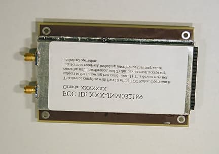
Click to zoom
Application Details
- Equipment Class
- DSS - Part 15 Spread Spectrum Transmitter
- Date of Grant
- Dec 05, 2002
- Application Purpose
- Original Equipment
- Date of Application
- Dec 05, 2002
- Equipment Note
- 902-928 MHz Radio with Antennas
- Frequency Range
- 902.00000000 - 928.00000000
- Country
- United States
Documents & Files
Document Text
Text extracted from the exhibit documents filed with the FCC. Open a document above to read the original.
Users Manual
User’s Guide User’s GuideUser’s Guide User’s Guide ATR900 Spread Spectrum Frequency Hopping Radio Modem It is essential that all instructions contained in this manual are followed precisely to ensure proper operation of equipment. FCC Notification This device complies with part 15 of the FCC rules. Operation is subject to the following conditions: 1) This device may not cause harmful interference and 2) This device must accept any interference received, including interference that may cause undesired operation. The device must be operated as supplied by the manufacture. Any changes or modifications made to the device without the express written approval may void the user’s authority to operate the device. Note: This equipment has been tested and found to comply with the limits for a Class A digital device, pursuant to part 15 of the FCC Rules. These limits are designed to provide reasonable protection against harmful interference in a industrial installation. This equipment generates, uses and can radiate radio frequency energy and, if not installed and used in accordance with the instructions, may cause harmful interference to radio communications. However, there is no guarantee that interference will not occur in a particular installation. If this equipment does cause harmful interference to radio or television reception, which can be determined by turning the equipment off and on, the user is encouraged to try to correct the interference by one or more of the following measures: ! Reorient or relocate the receiving antenna. ! Increase the separation between the equipment and receiver. ! Connect the equipment into an outlet on a circuit different from that to which the receiver is connected. ! Consult the dealer or an experienced radio/TV technician for help. Note: Whenever any ATR900 radio modem is placed inside an enclosure a label must be placed on the outside of that enclosure which includes the modem's FCC ID. The following antennas are approved for use with ATR900 series modems. 900MHz Directional Antenna Antenna model number Manufacture Type TB2-900SMA Hankook Antenna Omni whip w/SMA connector ACE 915 Ace Omni whip w/SMA connector MAX-9053 Maxrad Omni w/N connector YA6-900 Larsen Yagi w/N connetor Caution: The ATR900 has a maximum transmitted output power of 1W. It is recommended that transmit antenna be kept at least 20cm away from nearby persons to satisfy FCC RF exposure requirements. As part of the RF Exposure assessment procedure, you should also note any additional transmitting antennas in the immediate area that, because they are co-located with yours, could cause the maximum radiated energy to exceed a safe level. Using a Different Antenna In certain circumstances it may be desirable to extend the range of the ATR900 radio modem by using an external antenna in place of the standard whip antenna. The radio modem is equipped with a standard SMA external jack. This allows the use of one of the other certified antennas provided by the manufacture – See the list on the previous page. The use of a different antenna may radically improve the results obtained with ATR900 radio modems. It is imperative to obtain line of sight with the antennas, and changes in placement height of as few as a couple of feet may make the difference between no link and one that is solid and reliable. These antennas allow versatility in the ATR900’s deployment, extending its range and allowing it to get around obstructions. If external directional antennas are used, FCC regulations concerning effective radiated power limitations must be followed. Caution : Any antenna placed outdoors must be properly grounded. It is required by FCC regulations that qualified personnel experienced in antenna installation and familiar with local codes and regulations complete the antenna installation. It is also required by FCC regulations that only approved antennas be used. Use extreme caution when installing antennae and follow all instructions included with the antennas. The use of external antennae subjects the radio modem to greater exposure to direct lightning strikes. It is strongly recommended that a lightning arrestor be used on all outdoor antenna installations. Long RS232 cable runs should also be avoided in areas with increased lightning activity or static electricity unless they are properly isolated from the radio modem. Nearby lightning strikes or elevated levels of static electricity may lead to voltage spikes on the line, causing failure in the radio modem’s RS232 interface. It is also recommended that the RS232 data cable not be located near high voltage power lines as this can cause interference in data communications, damage the ATR900 as well as an increase in risk of personal injury.
ID Label/Location Info
FCC ID: QJ7-JNM032189 Canada: XXXXXXX This device complies with Part 15 of the FCC Rules. Operation is subject to the following two conditions: 1) This device may not cause harmful interference, and 2) this device must accept any interference received, including interference that may cause undesired operation.
Test Report
APPLICANT: COMMUNICATIONS DEVELOPMENT LLC FCC ID: QJ7-JNM032189 REPORT #: T:\C\CommunicationsDevelopment_QJ7\776ZUT2\776UT2TestReport.doc TABLE OF CONTENTS APPLICANT: COMMUNICATIONS DEVELOPMENT LLC FCC ID: QJ7-JNM032189 TABLE OF CONTENTS TEST REPORT CONTAINING: PAGE 1.............TEST PROCEDURE PAGE 2-4...........EQUIPMENT LIST PAGE 5.............15.247(a)-DEFINITION OF HOPS INCLUDING PLOT PAGE 6.............15.247(a)(1) - # OF HOPS INCLUDING PLOT PAGE 7-8...........15.247(a)(1)(i)- DWELL TIME OF HOP INCLUDING PLOTS PAGE 9.............15.247(a)(1)(i)-20 dB BANDWIDTH INCLUDING PLOTS PAGE 10............15.35 DESCRIPT OF 20 dB PULSED EMISSION CORR. FACTOR PAGE 11............15.247(b)(3)-DESCRIPTIONS OF ANTENNAS PAGE 12............15.247(4)(c)-100 kHz BANDWIDTH INCLUDING PLOT PAGE 13............15.247(b)(2)-POWER OUTPUT PAGE 14............METHOD OF MEASURING RF CONDUCTED SPURIOUS EMISSIONS SPURIOUS EMISSIONS AT ANTENNA TERMINALS TEST DATA PAGE 15-18.........RADIATION INTERFERENCE TEST DATA PAGE 19............METHOD OF MEASURING RADIATED SPURIOUS EMISSIONS PAGE 20............MPE CALCULATION EXHIBIT ATTACHMENTS: EXHIBIT 1...........REQUEST FOR CONFIDENTIALITY LETTER EXHIBIT 2...........FCC ID LABEL SAMPLE EXHIBIT 3...........SKETCH OF FCC ID LABEL LOCATION EXHIBIT 4...........EXTERNAL PHOTOGRAPHS EXHIBIT 5...........INTERNAL PHOTOGRAPHS EXHIBIT 6...........BLOCK DIAGRAM EXHIBIT 7...........SCHEMATICS EXHIBIT 8...........INSTRUCTION MANUAL EXHIBIT 9...........TEST SET UP PHOTOGRAPHS EXHIBIT 10..........OPERATIONAL DESCRIPTION APPLICANT: COMMUNICATIONS DEVELOPMENT LLC FCC ID: QJ7-JNM032189 REPORT #: T:\C\CommunicationsDevelopment_QJ7\776ZUT2\776UT2TestReport.doc Page 1 of 20 TEST PROCEDURE GENERAL: This report shall NOT be reproduced except in full without the written approval of TIMCO ENGINEERING, INC. The UUT was transmit- ting a test signal during the testing. 15.247(a)(1) CARRIER FREQUENCY SEPARATION & NUMBER OF CHANNELS: A near field probe was used to sense the signal of the UUT. The UUT was made to hop its full range. The spectrum analyzer was set to view the frequency range from 902 to 928 MHz and placed in the memory mode. A plot was then made of the display showing the number of channels. 15.247(a)(1)(i) CARRIER FREQUENCY DWELL TIME: A near field probe was used to sense the signal of the UUT. The UUT was made to hop its full range. The spectrum analyzer was set to view the frequency range from 902 to 928 MHz and the center of the HOPPING RANGE was centered on the Spectrum Analyzer. The SPAN was then set to ZERO(0) and the SWEEP TIME was set to 20 seconds. Then by analyzing the plot of the total ON TIME of the UUT during the 20 seconds. 15.247(b)(2) POWER OUTPUT: The RF power output was measured at the antenna feed point by removing the permanent antenna and connecting the UUT to a peak power meter, HP Model No. 8900C. 15.247(c) ANTENNA CONDUCTED EMISSIONS: The RBW=100 kHz, VBW =1.0 MHz up to 1000 MHz and RBW=1 MHz & VBW=3 MHz above 1 GHz. The spectrum was scanned from 30 MHz to the 10th Harmonic of the fundamental. RADIATION INTERFERENCE: The test procedure used was ANSI STANDARD C63.4-1992 using a HEWLETT PACKARD spectrum analyzer with a prese- lector. The analyzer was calibrated in dB above a microvolt at the output of the antenna. The resolution bandwidth was 100 kHz and the video bandwidth was 300 kHz up to 1.0 GHz and 1.0 MHz with a video BW of 3.0 MHz above 1.0 GHz. The ambient temperature of the UUT was 89°F, with a humidity of 47%. The hopping was stopped at the low end, middle and high end of the band in order to test the radiated emis- sions. FORMULA OF CONVERSION FACTORS: The Field Strength at 3 m was estab- lished by adding the meter reading of the spectrum analyzer (which is set to read in units of dBuV) to the antenna correction factor supplied by the antenna manufacturer. The antenna correction factors are stated in terms of dB. The gain of the Preselector was accounted for in the Spectrum Analyzer Meter Reading. Example: Freq (MHz) METER READING + ACF = FS 33 20 dBuV + 10.36 dB = 30.36 dBuV/m @ 3m APPLICANT: COMMUNICATIONS DEVELOPMENT LLC FCC ID: QJ7-JNM032189 REPORT #: T:\C\CommunicationsDevelopment_QJ7\776ZUT2\776UT2TestReport.doc Page 2 of 20 EMC Equipment List DEVICE MFGR MODEL SERNO CAL/CHAR DATE DUE DATE or STATUS X 3-Meter OATS TEI N/A N/A Listed 12/22/99 12/22/02 3/10-Meter OATS TEI N/A N/A Listed 3/26/01 3/26/04 Receiver, Beige Tower Spectrum Analyzer (Tan) HP 8566B Opt 462 3138A07786 3144A20661 CAL 8/31/01 8/31/03 RF Preselector (Tan) HP 85685A 3221A01400 CAL 8/31/01 8/31/03 Quasi-Peak Adapter (Tan) HP 85650A 3303A01690 CAL 8/31/01 8/31/03 X Receiver, Blue Tower X Spectrum Analyzer (Blue) HP 8568B 2928A04729 2848A18049 CHAR 10/22/01 10/22/03 X RF Preselector (Blue) HP 85685A 2926A00983 CHAR 10/22/01 10/22/03 X Quasi-Peak Adapter (Blue) HP 85650A 2811A01279 CHAR 10/22/01 10/22/03 X Biconnical Antenna Electro-Metrics BIA-25 1171 CAL 4/26/01 4/26/03 Biconnical Antenna Eaton 94455-1 1096 CAL 10/1/01 10/1/03 Biconnical Antenna Eaton 94455-1 1057 CHAR 3/15/00 3/15/02 BiconiLog Antenna EMCO 3143 9409-1043 X Log-Periodic Antenna Electro-Metrics LPA-25 1122 CAL 10/2/01 10/2/03 Log-Periodic Antenna Electro-Metrics EM-6950 632 CHAR 10/15/01 10/15/03 Log-Periodic Antenna Electro-Metrics LPA-30 409 CHAR 10/16/01 10/16/03 Dipole Antenna Kit Electro-Metrics TDA-30/1-4 152 CAL 3/21/01 3/21/04 Dipole Antenna Kit Electro-Metrics TDA-30/1-4 153 CHAR 11/24/00 11/24/03 Double-Ridged Horn Antenna Electro-Metrics RGA-180 2319 CAL 12/19/01 12/19/03 Horn Antenna Electro-Metrics EM-6961 6246 CAL 3/21/01 3/21/03 Horn Antenna ATM 19-443-6R None No Cal Required Passive Loop Antenna EMC Test Systems EMCO 6512 9706-1211 CHAR 7/10/01 7/10/03 Line Impedance Stabilization . . . Electro-Metrics ANS-25/2 2604 CAL 10/9/01 10/9/03 APPLICANT: COMMUNICATIONS DEVELOPMENT LLC FCC ID: QJ7-JNM032189 REPORT #: T:\C\CommunicationsDevelopment_QJ7\776ZUT2\776UT2TestReport.doc Page 3 of 20 DEVICE MFGR MODEL S…
Text truncated - open the document above for the full version.
Contact Information
Applicant
Jamie Stubner(Registered Agent)
Test Firm
Timco Engineering, Inc.S Sanders
Technical Specifications
| # | Rule Parts | Frequency Range | Power Output |
|---|---|---|---|
| 1 | 15C | 902 MHz - 928 MHz | 1 W |
Other Applications from Communications Development LLC
QJ7-JLM051690
Feb 16, 2004WIRELESS LAN
Equipment Class
DTS - Digital Transmission System