QKH-2YEKN001BLUETOOTH SPEAKER
Kanto Living Inc.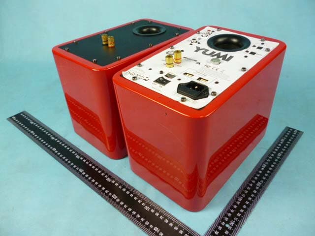
Click to zoom
Application Details
- Equipment Class
- DSS - Part 15 Spread Spectrum Transmitter
- Date of Grant
- Nov 11, 2012
- Application Purpose
- Original Equipment
- Date of Application
- Nov 11, 2012
- Equipment Note
- BLUETOOTH SPEAKER
- Frequency Range
- 2402.00000000 - 2480.00000000
- Company
- Kanto Living Inc.
- Country
- Canada
Documents & Files
Document Text
Text extracted from the exhibit documents filed with the FCC. Open a document above to read the original.
Users Manual
User Manual YUMI Powered Speaker System www.kantospeakers.com [email protected] Tel 604.231.9574 Fax 604.231.9535Supporting your digital lifestyle ™ Limited Warranty To Original Purchaser Kanto AV Systems (Kanto) warrants the equipment it manufactures to be free from defects in material and workmanship for the following limited warranty period of: 24 months parts and labour If equipment fails because of such defects and Kanto or an authorized dealer is notified within 24 months from the date of shipment with proof of original invoice. Kanto will, at its option, repair or replace the equipment, provided that the equipment has not been subjected to mechanical, electrical, or other abuse or modifications. Equipment that fails under conditions other than those covered will be repaired at the current price of parts and labor in effect at the repair. Such repairs are warranted for 90 days from the day of reshipment to the original purchaser. This warranty is in lieu of all other warranties expressed or implied, including without limitation, any implied warranty or merchantability or fitness for any particular purpose, all of which are expressly disclaimed. The information in the owner’s manual has been carefully checked and is believed to be accurate. However, Kanto assumes no responsibility for any inaccuracies that may be contained in the manual. In no event will Kanto, be liable for direct, indirect, special, incidental, or consequential damages resulting from any defect or omission in this manual, even if advised of the possibility of such damages. Warranty For more TV and desktop mounts, along with our other pr oducts, please visit kantoav.com. “LIKE” Kanto on Facebook to receive upcoming news and special product offers. • 5” passive 4Ω coaxial speakers with 1” tweeter • 50 Watt per side power handling capability • Inset M8 threaded nut for mounting with SWB100 • Available in a stunning array of mix and match colors • Compatible with YARO Amp for your digital media Kanto BEN Speakers • 3D and 1080p HD Full Colour Capabilities • 24 kt gold plated contacts • HDMI Ethernet Channel Kanto Infinity Series Cables • Metal head connectors with flex relief and grip • Visit kantospeakers.com for more! 12-10 English Check out more great products from Kanto! YUMI POWERED SPEAKER SYSTEM 215 Supporting your digital lifestyle ™ Table of Contents Important Safety Precautions . . . . . . . 2 Introduction / What’s in the Box? . . . . . 3 Front & Rear Panels . . . . . . . . . . . . 4 Remote Control . . . . . . . . . . . . . . 5 Setting Up Your Speakers . . . . . . . . . 6 Bluetooth ® Pairing / Bluetooth Operation / USB Charging Operation . . . . . . . . . 7 Use with iPods, iPhones, iPads . . . . . . 8 Use with MP3 Players . . . . . . . . . . . 9 Use with iPod / iPhone Docks . . . . . . . .10 Use with Auxiliary Sources . . . . . . . . . .11 Use with PC or Laptop . . . . . . . . . . . .12 Use with Optical Devices . . . . . . . . . .13 Connecting a Sub-Woofer . . . . . . . . . .14 Specifications . . . . . . . . . . . . . . . .15 Other Kanto Products / Warranty . . . . . .16 Important Safety Precautions • Read these instructions. • Keep these instructions. • Heed all warnings. • Follow all instructions. • Do not use this apparatus near water. • Clean only with a dry cloth. • Do not block any ventilation openings. Install in accordance with the manufacturer’s instructions. • Do not install near any heat sources such as radiators, heat registers, stoves, or other apparatus (including amplifiers) that produce heat. • Do not defeat the safety purpose of the polarized or grounding-type plug. A polarized plug has two blades with one wider than the other. A grounding type plug has two blades and a third grounding prong. The wide blade or the third prong are provided for your safety. If the plug provided does not fit into your outlet, consult an electrician for replacement of the obsolete outlet. • Protect the power-supply cord from being walked on or pinched, particularly at plugs, convenience receptacles and the point where they exit from the apparatus. • Only use attachments / accessories specified by the manufacturer. • Use only with the cart, stand, tripod, bracket, or table specified by the manufacturer, or sold with the apparatus. When a cart is used, use caution when moving the cart/ apparatus combination to avoid injury from tip-over. • Unplug this apparatus during lightning storms or when unused for long periods of time. • Refer all servicing to qualified service personnel. Servicing is required when the apparatus has been damaged in any way, such as power-supply cord or plug is damaged, liquid has been spilled or objects have fallen into the apparatus, the apparatus has been exposed to rain or moisture, the apparatus does not operate normally, or the apparatus has been dropped. • Apparatus shall be connected to a MAINS socket outlet with a protective earthing connection. • An appliance input coupler is used as the disconnect device - the disconnect device shall remain readily operable. • Batteries or battery packs shall not be exposed to excessive heat such as sunshine, fire or the like. CAUTION: TO REDUCE THE RISK OF ELECTRIC SHOCK, DO NOT REMOVE BACK PANEL. NO USER SERVICEABLE PARTS INSIDE. REFER SERVICING TO QUALIFIED SERVICE PERSONNEL. DANGEROUS VOLTAGE The lightning flash with arrowhead, within an equilateral triangle, is intended to alert the user of the presence of non-insulated “dangerous voltage” within the product’s enclosure that may be of sufficient magnitude to constitute a risk of electric shock to persons. ATTENTION The exclamation point within an equilateral triangle is intended to alert the user of the presence of important operating and maintenance (servicing) instructions in the literature accompanying the apparatus. Specifications YUMI POWERED SPEAKER SYSTEM Tweeter 1 inch silk dome Woofer 5 inch Kevlar Nominal Impedance 6 Ohm Sensitivity 2.83V (/1W/1m) 87 dB Power Output 30 Watts RM…
Text truncated - open the document above for the full version.
Block Diagram
MCU STC12C5404AD AUX IN Bluetooth Module BTM512 Crystal 26MHz AMP PT2314 SP SP Power Crystal 12MHz Optical IN
Cover Letter(s)
Kanto Distribution Inc. 150- 4320 Viking Way, Richmond, BC Canada Attestation Statement The USB port is only for USB charge, not for data transfer.
External Photos
Page 1 of 2 External PHOTO: Model: YUMI Page 2 of 2
ID Label/Location Info
GUANG ZHOU SONICSTAR ELECTRONICS CO.LTD 广州笙达电器有限公司 美术稿确认表 ARTWORK APPROVAL FORM: Content: 设计/日期 审核/日期 批准/日期 Part No./编号: Part Name./品名: Model No./型号: Brand Name./铭牌:Date./日期: Job No./工作表编号: 2 3 8 m m 148 mm MG-01 YUMI 2012-10-26 主箱后板丝印 Kanto 要求: 1、丝印内容正确; 2、丝印图字清晰, 位置准确; 3、丝印色:白色 / DR-KN1101(E)-01 FCC ID: QKH-2YEKN001 IC: 10678A-2YEKN001 Model:
Internal Photos
Page 1 of 5 Internal PHOTO: Model: YUMI PCB: Page 2 of 5 Page 3 of 5 Page 4 of 5 Page 5 of 5
Operational Description
Operational Description Product Description This product integrated a Bluetooth chipset to support the Bluetooth function that allows users to use it as a speaker as the primary usage of this device. The brief introduction of the circuit 1. The Bluetooth signal is transmitted and received through the antenna system consists of the PCB antenna. 2. Power of the whole body is provided by 110-120/230-240Vac. 3. Line in port is to connect audio source by line in cable to input audio signal. ON/OFF button is to turn on or turn off the speaker. 4. IC14 is MCU master control IC, it is use to button control, input Switch between Bluetooth and line in, and output audio source to amplifier IC. 5. IC4 is to amplify audio signal provided by master control IC and motivate loudspeakers. Technical Description of FHSS The Bluetooth standard describes a frequency hopping spread spectrum system (FHSS). The frequency hopping sequence is governed by one unit known as the master in any group of units communicating together. The group is known as a piconet, and all units other than the master are known as slaves. The master determines the pseudo random hopping sequence internally and without reference to any external information, there is no co-ordination with any other Bluetooth or other FHSS systems to avoid simultaneous occupancy of hopping channels. Bluetooth uses re-transmission, interleaving and coding techniques to mitigate against lost transmissions when simultaneous occupancy of a channel cause loss of data. The pseudo random hopping sequence is initialized at the start of a new connection between master and slave to a random frequency ( hopping channel ), and the hopping sequence is generated such that an equal time is spent in each of 79 channels throughout the duration of the connection. The antenna supplied with the unit is a short monopole of 1/4 wavelength with a nominal gain of 0 dBi. The antenna is an integral part of the device. The peak power of the BC01 transceiver is approximately 0 dBm, and the maximum EIRP is approximately 0 dBm.
RF Exposure Info
RF Exposure Compliance Requirement 1. Standard requirement Syste ms operating under the provisions of this section shall be operated in a manner th at ensures th at the public is not exposed to radio frequency energy level in excess limit for maximum permissible exposure. In accordance with 47 CFR FCC Part 2 Subpart J, section 2.1091 and RSS 102 this device has been defined as a mobile device whereby a distance of 0.2m normally can be maintained between the user and the device. (a) Limits for Occupational / Controlled Exposu re Frequency Range (MHz) Electric Field Strength (E) (V/m) Magnetic Field Strength (H) (A/m) Power Density (S)(mW/c m 2 ) Averaging Times | E | 2 , |H | 2 or S (minutes) 0.3-3.0 614 1.63 (100)* 6 3.0-30 1842/f 4.89/f (900/f)* 6 30-300 61.4 0.163 1.0 6 300-1500 F/300 6 1500-100000 5 6 (b) Limits for General Popula tion / Uncontrolled Exposure Frequency Range (MHz) Electric Field Strength (E) (V/m) Magnetic Field Strength (H) (A/m) Power Density (S)(mW/c m 2 ) Averaging Times | E| 2 , |H| 2 or S (minutes) 0.3-1.34 614 1.63 (100)* 30 1.34-30 824/f 2.19/f (180/f)* 30 30-300 27.5 0.073 0.2 30 300-1500 F/500 30 1500-100000 1.0 30 Note: f=frequency in MHz; *Plane-wave equivalent power density 2. MPE Calcula tion Method E (V/m)=(30*P*G) 0.5 /d Power Density: Pd(W/m 2 )=E 2 /377 E=Electric Field (V/m) P=Peak RF output Power (W) G=EUT Antenna numeric gain (numeric) d= Separation distance between radiator and human body (m) The formula can be changed to Pd= (30*P*G)/(377*d 2 ) From the peak EUT RF output power, the minimum mobile separation distance, d=0.2m, as well as the gain of the used antenna, the RF power density can be obtained. 3. Calcula ted Result and Limit 1) Normal: Frequenc y (MHz) Antenna Gain (Numeric) Peak Output Power (dBm) Peak Output Power (mW) Power Density (S) (mW/cm 2 ) Limit of Power Density (S) (mW/cm 2 ) Test Result 2402 1.0 5.401 3.468 0.0007 1 Compli ance 2441 1.0 4.935 3.115 0.0006 1 Compli ance 2480 1.0 3.638 2.311 0.0005 1 Compli ance EDR: Frequenc y (MHz) Antenna Gain (Numeric) Peak Output Power (dBm) Peak Output Power (mW) Power Density (S) (mW/cm 2 ) Limit of Power Density (S) (mW/cm 2 ) Test Result 2402 1.0 5.4 22 3.485 0.0007 1 Compli ance 2441 1.0 4.968 3.139 0.0006 1 Compli ance 2480 1.0 3.6 94 2.341 0.0005 1 Compli ance
Schematics
1 2 3 4 5 6 ABCD 6 5 4 3 2 1 D CBA Title Number Revision Size C Date: 22-Oct-2009 Sheet of File: D:\Coordiwise\design\module\BTM _51\BTM_51_V01C\BTM_51_V01C.ddb Drawn By: RF_N L1 RF_P K1 RX_N J1 RX_P H1 AUX_DAC H2 VSS_AUDIO A1 VSS_AUDIO D3 VSS_DIG B4 VSS_DIG C4 VSS_DIG C12 VSS_DIG C13 VSS_DIG C14 VSS_DIG H3 VSS_DIG L13 VSS_DIG N4 VSS_DIG N8 VSS_DIG N13 VSS_RADIO J2 VSS_RADIO K2 VSS_RADIO L2 VSS_LO K3 VSS_LO L3 VSS_ANA P2 VSS C3 VSS F6 VSS F7 VSS F8 VSS F9 VSS F10 VSS G6 VSS G7 VSS G8 VSS G9 VSS G10 VSS H6 VSS H7 VSS H8 VSS H9 VSS H10 VSS J3 VSS J6 VSS J7 VSS J8 VSS J9 VSS J10 VSS K6 VSS K7 VSS K8 VSS K9 VSS K10 VSS M3 BAT_N B12 SUBS R3 NC G2 NC P4 REB C11 CSB A10 WEB N7 A0 C9 A1 P12 A2 R12 A3 N11 A4 P11 A5 R11 A6 N10 A7 P10 A8 P7 A9 R7 A10 N6 A11 P6 A12 R6 A13 N5 A14 P5 A15 R5 A16 P9 A17 R10 A18 N9 D0 B11 D1 C10 D2 A9 D3 B8 D4 B7 D5 C6 D6 A6 D7 B5 D8 A11 D9 B10 D10 C8 D11 C7 D12 A7 D13 B6 D14 C5 D15 A5 A19 P8 A20 N12 FLASH_RP R9 SPK_A_N E2 SPK_A_P E1 SPK_B_N D2 SPK_B_P D1 MIC_A_P C2 MIC_A_N C1 MIC_B_P B2 MIC_B_N B1 MIC_BIAS B3 AU_REF E3 RST G13 TESET_EN G14 LO_REF P3 AIO0 R4 AIO1 N3 UART_CTS P15 UART_RTS R15 UART_RX N14 UART_TX N15 USB_DN P13 USB_DP P14 SPI_CLK E14 SPI_CSB E15 SPI_MOSI E13 SPI_MISO D15 PCM_CLK F13 PCM_SYNC F14 PCM_IN G15 PCM_OUT F15 PIO0 F1 PIO1 F2 PIO2 G3 PIO3 F3 PIO4 H13 PIO5 H14 PIO6 H15 PIO7 J13 PIO8 J14 PIO9 M14 PIO10 M13 PIO11 L14 PIO12 K13 PIO13 K14 PIO14 J15 PIO15 M15 LED0 D13 LED1 D14 XTAL_IN R1 XTAL_OUT R2 VDD_USB R14 VDD_PADS L15 VDD_MEM A4 VDD_MEM A8 VDD_MEM B9 VDD_MEM R8 VDD_MEM R13 VDD_PIO G1 VDD_AUDIO A2 VREGIN_AUDIO A3 VREGOUT_H B15 VREGIN_H A15 VREGENABLE_H B14 BAT_P B13 VDD_CHG A12 VDD_SMP_CORE A14 LX A13 VREGIN_L N2 VREGENABLE_L M2 VDD_ANA P1 VDD_CORE C15 VDD_CORE K15 VDD_RADIO M1 VDD_LO N1 U1 BC5 MM EXTERNAL X12 6MHz/10ppm C10 6p8F/16V/C0G C11 20pF/16V/C0G PCM_CLKPCM_OUTPCM_INPCM_SYNCSPI_CLKSPI_MISOSPI_MOSISPI_CSBUART_CTSUART_TXUART_RTSUART_RXUSB_DPUSB_DNAIO0AIO1PIO0PIO1PIO2PIO3PIO4PIO5PIO6PIO7PIO8PIO9PIO10PIO11PIO12PIO13PIO14PIO15 REB G1 CSB F1 WEB A4 A0 E1 A1 D1 A2 C1 A3 A1 A4 B1 A5 D2 A6 C2 A7 A2 A8 B5 A9 A5 A10 C5 A11 D5 A12 B6 A13 A6 A14 C6 A15 D6 A16 E6 A17 B2 A18 C3 D0 E2 D1 H2 D2 E3 D3 H3 D4 H4 D5 E4 D6 H5 D7 E5 D8 F2 D9 G2 D10 F3 D11 G3 D12 F4 D13 G5 D14 F5 D15 G6 VCC G4 BYTEB F6 RPB B4 NC B3 NC D3 NC C4 R/BB A3 NC D4 VSS H1 VSS H6 U3S29AL008D +3V3 SPK_A_N SPK_A_P SPK_B_P SPK_B_N C14 47nF/16V/X7R +3V3 +3V3 +3V3 +3V3 +1V8 +1V5_A C8 10nF/16V/X7R C7 2u2F/10V/X5R R3 2R2 +3V3 +1V5 C3 10nF/16V/X7R +1V8 C1 47pF/16V/C0G C2 2u2F/10V/X5R R2 2R2 +3V3 C9 10nF/16V/X7R +3V3 C20 10nF/16V/X7R C13 47nF/16V/X7R +3V3 RF_IO 1 2 TP1 L2 22nH/5% C12 47pF/16V/C0G +1V5 RF_IO UNB 1 DC 2 NC 3 BAL 4 GND 5 BAL 6 GND 7 GND 8 U2 DBF81F107 MIC_A_P MIC_A_N MIC_B_N MIC_B_P MIC_A_N 1 MIC_A_P 2 MIC_B_N 3 MIC_B_P 4 MIC_BIAS 5 AIO0 6 AIO1 7 +1V8 8 +3V3 9 UART_RX 10 UART_RTS 11 UART_TX 12 UART_CTS 13 GND 14 USB_DP 15 USB_DN 16 PCM_CLK 17 PCM_IN 18 PCM_SYNC 19 PCM_OUT 20 PIO9 21 PIO6 22 VCHG 23 PIO5 24 GND 25 SPI_MISO 26 SPI_CSB 27 SPI_CLK 28 SPI_MOSI 29 PIO12 30 PIO4 31 PIO11 32 PIO10 33 NC 34 VBAT 35 GND 36 RF_IO 37 GND 38 GND 39 PIO2 40 PIO3 41 PIO0 42 PIO1 43 SPK_B_N 44 SPK_B_P 45 SPK_A_N 46 SPK_A_P 47 AGND 48 J1 BTM_51_V01B GNDGNDGND GND PIO4 PIO3PIO9 PIO12PIO11 UART_CTSUART_RTSUART_RXUART_TX USB_DNUSB_DP RF_IOSPI_CLKSPI_CSBSPI_MISOSPI_MOSI PCM_CLKPCM_IN PCM_OUT PCM_SYNC +3V3MIC_BIASAIO1MIC_A_PMIC_A_NMIC_B_PMIC_B_N SPK_A_NSPK_A_PSPK_B_NSPK_B_P LED0LED1 CS 1 SO 2 WP 3 GND 4 SI 5 SCK 6 HOLD 7 VCC 8 U4AT26DF081A PIO3PIO2 PIO0PIO1 R52K2 R6 2K2 R42K2 R12K2 +3V3 +3V3 +3V3 +3V3 +3V3 +3V3 +3V3 C5 10nF/16V/X7R C6 2u2F/10V/X5R VBAT ADDR0 ADDR1 ADDR2 ADDR3 ADDR4 ADDR5 ADDR6 ADDR7 ADDR8 ADDR9 ADDR10 ADDR11 ADDR12 ADDR13 ADDR14 ADDR15 ADDR16 ADDR17 ADDR18 ADDR19 ADDR19 DATA0 DATA1 DATA2 DATA3 DATA4 DATA5 DATA6 DATA7 DATA8 DATA9 DATA10 DATA11 DATA12 DATA13 DATA14 DATA15 R7 0R MIC_BIAS L1 22uH +1V8 C4 4u7F/10V/X5R PIO0PIO1PIO2 PIO10 R8 1K R9 1K SPK_A_N SPK_A_P SPK_B_N SPK_B_P AIO0+1V8 PIO5PIO6 VBAT GND VCHG VCHG R10 0R +3V3
Test Report
ITL Page 1 of 67 Report No.: 12102889 TEST REPORT Applicant: Kanto Distribution Inc. Address of Applicant: 150-4320 Viking Way, Richmond, BC Canada Manufacturer: Sonicstar (Guangzhou) Electronics Co., Ltd Address of Manufacturer: No.13 Taoyuan West Street, Shima, Junhe, Baiyun District, Guangzhou, 510440, China Product name: Powered Speaker system Model: YUMI Rating(s): 110-120V~ 60Hz 120W 230-240V~ 50Hz 120W Trademark: kanto Standards: FCC Part 15.247 :2010 RSS-210 issue 8 FCC ID: QHK-2YEKN001 IC ID: 10678A-2YEKN001 Data of Receipt: 2012-10-10 Date of Test: 2012-10-11~2012-10-26 Date of Issue: 2012-10-29 Test Result Pass* * In the configuration tested, the test item complied with the standards specified above. Authorized for issue by: Test by: Reviewed by: Oct.29.2012 Jumy Qiu Oct.29.2012 Pauler Li Project Engineer Project Engineer Date Name/Position Signature Date Name/Position Signature ITL Page 2 of 67 Report No.: 12102889 Possible test case verdicts: test case does not apply to the test object .. : N/A test object does meet the requirement ........ : P (Pass) test object does not meet the requirement .. : F (Fail) Testing Laboratory information: Testing Laboratory Name .......... : I-Test Laboratory Address : 1-2 floor, South Block, Building A2 , No 3 Keyan Lu, Science City, Guangzhou, Guangdong Province, P.R. China Testing location : Same as above Tel : 0086-20-32209330 Fax : 0086-20-62824387 E-mail : [email protected] General remarks: The test results presented in this report relate only to the object tested. The results contained in this report reflect the results for this particular model and serial number. It is the responsibility of the manufacturer to ensure that all production models meet the intent of the requirements detailed within this report. This report would be invalid test report without all the signatures of testing technician and approver. This report shall not be reproduced, except in full, without the written approval of the Issuing testing laboratory. General product information: / ITL Page 3 of 67 Report No.: 12102889 1 Test Summary Test Test Requirement Test method Result Antenna Requirement FCC PART 15 C section 15.247 (c) and Section 15.203 FCC PART 15 C section 15.247 (c) and Section 15.203 PASS Occupied Bandwidth (99% and -20dB) FCC PART 15 C section 15.247 (a)(1); RSS 210 A8.1 (1) ANSI C63.10: Clause 6.9 & DA 00-705 PASS Carri er Frequencies Separated FCC PART 15 C section 15.247(a)(1); RSS 210 A8.1 (1) DA 00-705 PASS Hopping Channel Number FCC PART 15 C section 15.247(a)(1)(iii) RSS 210 A8.1 (4) DA 00-705 PASS Dwell Time FCC PART 15 C section 15.247(a)(1)(iii) ; RSS 210 A8.1 (4) DA 00-705 PASS Pseudorandom Frequency Hopping Sequence FCC PART 15 C section 15.247(a)(1); RSS 210 A8.1 (1) DA 00-705 PASS Maximum Peak Output Power FCC PART 15 C section 15.247(b)(1); RSS 210 A8.4 (2) ANSI C63.10: Clause 6.10 & DA 00-705 PASS Conducted Spurious Emission (30 MHz to 25 GHz) FCC PART 15 C section 15.247(d); RSS 210 A8.5 ANSI C63.10: Clause 6.7 & DA 00-705 PASS Radiated Spurious Emission (9 kHz to 25 GHz) FCC PART 15 C section 15.247(d); RSS 210 A8.5 ANSI C63.10: Clause 6.4, 6.5 and 6.6 & DA 00-705 PASS Band Edges Measurement FCC PART 15 C section 15.247 (d) &15.205 ANSI C63.10: Clause 6.9 & DA 00-705 PASS Conducted Emissions at Mains Terminals FCC PART 15 C section 15.207; RSS GEN Table 2 ANSI C63.10: Clause 6.2 & DA 00-705 PASS Remark: N/A: not applicable. Refer to the relative section for the details. EUT: In th is whole report EUT means Equipment Under Test. Tx: In th is whole report Tx (or tx) means Transmitte r. Rx: In this whole report Rx (or rx) means Receiver. RF: In this whole report RF means Radio Frequency. ANSI C63.10: the detail version is ANSI C63.10:2009 in the whole report. DA 00-705: “Filing and Measurement Guidelines for Frequency Hopping Spread Spectrum Systems” ITL Page 4 of 67 Report No.: 12102889 2 Contents Page TEST REPORT ....................................................................................................................................................................... 1 1 TEST SUMMARY ......................................................................................................................................................... 3 2 CONTENTS ................................................................................................................................................................... 4 3 GENERAL INFORMATION ........................................................................................................................................ 5 3.1 CLIENT INFORMATION ............................................................................................................................................ 5 3.2 GENERAL DESCRIPTION OF E.U.T. ....................................................................................................................... 5 3.3 DETAILS OF E.U.T. ................................................................................................................................................ 5 3.4 DESCRIPTION OF SUPPORT UNITS ........................................................................................................................ 5 3.5 TEST LOCATION ..................................................................................................................................................... 6 3.6 DEVIATION FROM STANDARDS .............................................................................................................................. 6 3.7 ABNORMALITIES FROM STANDARD CONDITIONS .................................................................................................. 6 3.8 OTHER INFORMATION REQUESTED BY THE CUSTOMER ....................................................................................... 6 3.9 TEST FACILITY .........................................................................................................…
Text truncated - open the document above for the full version.
Contact Information
Applicant
Rob Maudsley(Director of Engineering)
Test Firm
I-Test LaboratoryPauler Li
[email protected]00862032209330
Technical Specifications
| # | Rule Parts | Frequency Range | Power Output |
|---|---|---|---|
| 1 | 15C | 2.40 GHz - 2.48 GHz | 3.00 mW |
Other Applications from Kanto Living Inc.
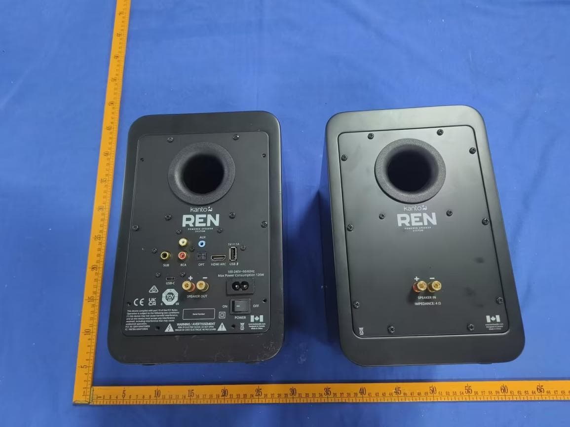
QKH-KANTOREN
Sep 17, 2024Powered Speaker System
Equipment Class
DTS - Digital Transmission System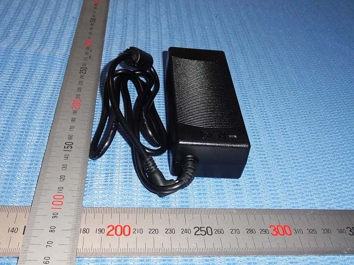
QKH-2YEKN007
Jan 25, 2015Powered Speaker system
Equipment Class
DSS - Part 15 Spread Spectrum Transmitter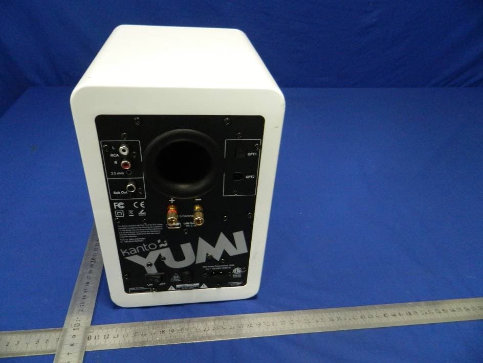
QKH-2YEKN002
Nov 17, 2013Active Loudspeaker System
Equipment Class
DSS - Part 15 Spread Spectrum Transmitter