QKL5110Radar Detector
Escort Incorporated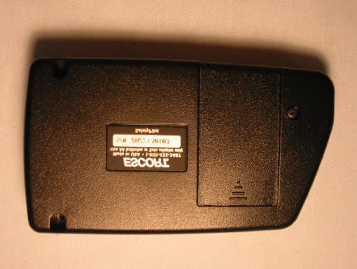
Click to zoom
Application Details
- Equipment Class
- CRD - Part 15 Radar Detector
- Date of Grant
- Sep 08, 2002
- Application Purpose
- Original Equipment
- Date of Application
- Sep 08, 2002
- Equipment Note
- Radar Detector
- Frequency Range
- 33400.00000000 - 36000.00000000
- Company
- Escort Incorporated
- Country
- United States
Documents & Files
Document Text
Text extracted from the exhibit documents filed with the FCC. Open a document above to read the original.
Users Manual
city mute dim pwr/vol ® O W N E R ' S M A N U A L ® Check Quick Reference Guide inside cover ! S O L O CORDLESS RADAR/LASER DETECTOR M O D E L R D - 5 1 1 0 CONGRATULATIONS! SOLO is the result of ESCORT’s commitment to design and manufacture the best radar and laser detection products available. Created for drivers who desire the ultimate in mobility, SOLO’s cordless design eliminates the need for a power cord, recharger, or add-on battery pack. Simply mount SOLO on your windshield and turn it on. SOLO uses only a fraction of the power of a conventional detector and two standard AA alkaline batteries will economically provide months of high-performance detection. Most drivers will need to replace SOLO’s batteries only a few times a year at a cost of only two or three cents per hour of use. SOLO comes with all of ESCORT’s most sophisticated technologies including our matchless DPR TM anti-falsing circuitry; true Digital Signal Processing; SafetyPilot TM road safety system; SmartShield TM VG2 protection and the incomparable performance you’ve come to expect from ESCORT. Among SOLO’s features are long-range warning on all radar and laser bands, Mute, AutoMute, patented SmartMute TM ; high- visibility display, differentiated audible and visual alerts, 4-level Dim, 4- level City, Memory retention, battery status indicator, battery-preserving AutoOff, optional power cord back-up, patented Easy-Mount system—all in the most compact and portable format available. SOLO was designed and manufactured in the USA. We are proud to offer this product and pleased to have you as our customer. Please drive safely. AUTOMUTE PROMOTES DRIVING PLEASURE SOLO is shipped with AutoMute engaged to provide you with the advantages of audible alerts but with minimal distraction. With AutoMute, the audio for the first four audible tones or four seconds (whichever is longer) in an alert situation will be emitted at the volume level you have set. All subsequent audible tones from the same alert situation will automatically be emitted at a lower volume level. After the signal has passed, your SOLO will automatically reset to the volume level you have set. (If you prefer full audio for the duration of all alert situations, AutoMute can be easily disengaged: see page 5 for more details.) Installing SOLO's Batteries ..........................................................1 Battery Life Indication ..............................................................1,7 Low Battery Warning ...............................................................2,7 AutoOff.......................................................................................2 Mounting SOLO..........................................................................3 Controls and Indicators Power On .............................................................................4 Volume.......................................................................................4 Mute...........................................................................................5 AutoMute....................................................................................5 Highway/City Modes.............................................................5 Dim Modes ...........................................................................5 Audible Alerts .......................................................................6 Power On Indicator...............................................................6 City Indicator ........................................................................6 Band Indicators .....................................................................6 Signal Meter..........................................................................6 Safety Signals ........................................................................6 Mounting Adjustment Button ................................................7 Radar Antenna ......................................................................7 Laser Lenses ..........................................................................7 Power Jack ............................................................................7 Programmable Options ...............................................................8 Tutorial Mode ...........................................................................10 Specifications...............................................................................11 Interpreting Alerts ......................................................................12 How Radar Works .....................................................................14 How Laser Works ......................................................................14 How Safety Signals Work...........................................................15 Troubleshooting..........................................................................16 Service........................................................................................18 Warranty....................................................................................19 Optional Accessories ................................................................20 T A B L E O F C O N T E N T S IMPORTANT BATTERY INFORMATION 1 SOLO is designed to operate on two standard AA alkaline batteries. AA lithium batteries and AA alkaline rechargeable batteries may also be used, however the resulting battery life will vary. We do not recommend using NiCad rechargeable batteries. Installing SOLO’s Batteries 1Make sure SOLO is turned off. 2Turn SOLO upside down. Depress the battery door and sliding in the direction of the arrow, remove door from the battery compartment. 3Remove any old batteries (both batteries MUST be replaced at the same time). 4Observing the polarity indication inside the battery compartment, insert two fresh AA alkaline batteries. 5Replace battery door. 6Turn SOLO on to verify correct battery installation. NOTE: Please dispose of used batteries properly in accordance…
Text truncated - open the document above for the full version.
Users Manual
Modifications not expressly approved by the manufacturer could void the user’s FCC granted authority to operate the equipment. Printed in Canada153003-00 11263_FCC card insert 8/28/02 5:06 PM Page 1 11263_FCC card insert 8/28/02 5:06 PM Page 2
Cover Letter(s)
Curtis-Straus LLC 527 Great Road Littleton, Massachusetts 01460 Tel: 978.486.8880 Fax: 978.486.8828 Web: www.curtis-straus.com Worldwide Regulatory Approvals Experts ® Federal Communications Commission 7435 Oakland Mills Road Columbia, MD 21046 Gentlemen: This letter is to comply with 47 CFR 0.457(d)(2) pertaining to confidential material. Escort, Inc. requests that the following documents regarding this submission for FCC ID: QKL5110 be kept confidential: 1. Block Diagram 2. Circuit Description 3. Schematics The material above contains technical data, which would customarily be guarded from competitors. We at Curtis-Straus LLC are acting as an Agent on behalf of Escort, Inc. in requesting confidentiality with regards to the preceding documents. Sincerely, Michael Buchholz Senior EMC Manager Curtis-Straus LLC 527 Great Road Littleton, MA 01460
External Photos
External Photos Model: Solo 5110 FCC ID: QKL5110 Model: Solo 5110 FCC ID: QKL5110 Model: Solo 5110 FCC ID: QKL5110
ID Label/Location Info
FCC ID:QKL5110 THIS DEVICE COMPLIES WITH PART 15 OF THE FCC RULES. OPERATION IS SUBJECT TO THE FOLLOWING TWO CONDITIONS: (1) THIS DEVICE MAY NOT CAUSE HARMFUL INTERFERENCE, AND (2) THIS DEVICE MUST ACCEPT ANY INTERFERENCE RECEIVED INCLUDING INTERFERENCE THAT MAY CAUSE UNDESIRED OPERATION. FCC ID:QKL7500 THIS DEVICE COMPLIES WITH PART 15 OF THE FCC RULES. OPERATION IS SUBJECT TO THE FOLLOWING TWO CONDITIONS: (1) THIS DEVICE MAY NOT CAUSE HARMFUL INTERFERENCE, AND (2) THIS DEVICE MUST ACCEPT ANY INTERFERENCE RECEIVED INCLUDING INTERFERENCE THAT MAY CAUSE UNDESIRED OPERATION. FCC ID: QKL8500 THIS DEVICE COMPLIES WITH PART 15 OF THE FCC RULES. OPERATION IS SUBJECT TO THE FOLLOWING TWO CONDITIONS: (1) THIS DEVICE MAY NOT CAUSE HARMFUL INTERFERENCE, AND (2) THIS DEVICE MUST ACCEPT ANY INTERFERENCE RECEIVED INCLUDING INTERFERENCE THAT MAY CAUSE UNDESIRED OPERATION. FCC ID: QKLSRX THIS DEVICE COMPLIES WITH PART 15 OF THE FCC RULES. OPERATION IS SUBJECT TO THE FOLLOWING TWO CONDITIONS: (1) THIS DEVICE MAY NOT CAUSE HARMFUL INTERFERENCE, AND (2) THIS DEVICE MUST ACCEPT ANY INTERFERENCE RECEIVED INCLUDING INTERFERENCE THAT MAY CAUSE UNDESIRED OPERATION.
Internal Photos
Internal Photos Model: Solo 5110 FCC ID: QKL5110 Model: Solo 5110 FCC ID: QKL5110 Model: Solo 5110 FCC ID: QKL5110
Test Report
Company: Escort, Inc. FRN: 0007508732 Model: Solo 5110 FCC ID: QKL5110 Equipment Code: CRD Report prepared for: Report prepared by: Escort, Inc. Evan D. Gould 5440 West Chester Road Curtis-Straus LLC West Chester, OH 45069 527 Great Road Phone: (513)-870-8535 Phone: (978)-486-8880 FAX: (513)-870-8523 FAX: (978)-486-8828 EMC Manager Worldwide Regulatory Approvals Experts (A2LA Certificate Number 1627-01) Technical Report REPORT:C0610-10 FCC ID:QKL5110 Page 2 of 8 Introduction This report is an application for Certification of a Radar Detector operating pursuant to 47 CFR 15.109, as amended by ET Docket No. 01-278; FCC 02-211, published in the Federal Register Vol. 67, No. 145 on Monday July 29, 2002. REPORT:C0610-10 FCC ID:QKL5110 Page 3 of 8 Statement of Conformity 47 CFR 15.109(h) states that “Radar detectors shall comply with the emissions limits...of [section 15.109(a)] over the frequency range of 11.7 – 12.2GHz.” The applicable limit being 500μV/m measured at a distance of 3m. The Escort Solo 5110 has been tested and found to comply with this requirement. REPORT:C0610-10 FCC ID:QKL5110 Page 4 of 8 Test Methodology Radiated emission testing was performed according to the procedures in ANSI C63.4 (2001). The testing was performed at an antenna to EUT distance of 1 meter. Performance was investigated in the range 11.7-12.2GHz. The Solo 5110 was powered by fresh AA batteries. Since the device is a hand-held unit, the emissions were maximized around the three orthogonal axes and the maximum reading was recorded. The integrated antenna cannot be maximized separately. REPORT:C0610-10 FCC ID:QKL5110 Page 5 of 8 Test Equipment SPECTRUM ANALYZERS x Analyzer Model No. Company Serial No. Calibration Due X ORANGE 9kHz-26.5GHz E4407B HP US39440975 07-JUN-2003 OPEN AREA TEST SITES (OATS) x Site FCC Code IC Code VCCI Code Calibration Due X “T” Texas 93448 IC 2762-T R-905/ C-480 04-FEB-2004 ANTENNAS x Antenna Model No. Company Serial No. Calibration Due X BLACK Horn: 1-18GHz 3115 EMCO 9703-5148 12-JUN-2003 PREAMPLIFIERS / ATTENUATORS x Preamplifier Model No. Company Serial No. Calibration Due X ORANGE-BLACK 1-20GHZ SMC-12A MITEQ 690639 06-SEP-2002 Unless otherwise noted the calibration interval is one year. All equipment is calibrated using standards traceable to NIST or other nationally recognized calibration standard. All Open Area Test Sites are located at 527 Great Road, Littleton, MA 01460. REPORT:C0610-10 FCC ID:QKL5110 Page 6 of 8 Setup Photo Model: Solo 5110 REPORT:C0610-10 FCC ID:QKL5110 Page 7 of 8 Measurement Results All measurements taken were peak detector readings of the noise floor. There were no emissions detected from the EUT. Radiated Emissions Table Curtis-Straus LLC Date:08-Aug-02Company:EscortTable1 Engineer:Evan GouldEUT Desc:Solo 5110Work Order:C0610 Frequency Range:11.7-12.2GHzMeasurement Distance:1 m Notes:Emissions maximized Horizontally and Vertically. All measurements are noise floor readings. AntennaPreampAntennaCableAdjusted 47 CFR 15.209(a) PolarizationFrequencyReadingFactorFactorFactorReadingLimitMarginResult (H / V)(MHz)(dBμV)(dB)(dB/m)(dB)(dBμV/m)(dBμV/m)(dB)(Pass/Fail) Solo 12190.031.720.038.94.755.363.5-8.2Pass Test Sites:"T"Pre-Amp:Or-BlkCable:3m MicroflexAnalyzer:OrangeAntennas:Black Horn REPORT:C0610-10 FCC ID:QKL5110 Page 8 of 8 Emission Plot
Contact Information
Applicant
John R Kuhn(Vice President of Engineering)
[email protected]513-870-8500
Test Firm
Curtis-Straus LLCJonathan Stewart
Technical Specifications
| # | Rule Parts | Frequency Range | Power Output |
|---|---|---|---|
| 3 | 15B | 33.40 GHz - 36.00 GHz | - |
Other Applications from Escort Incorporated
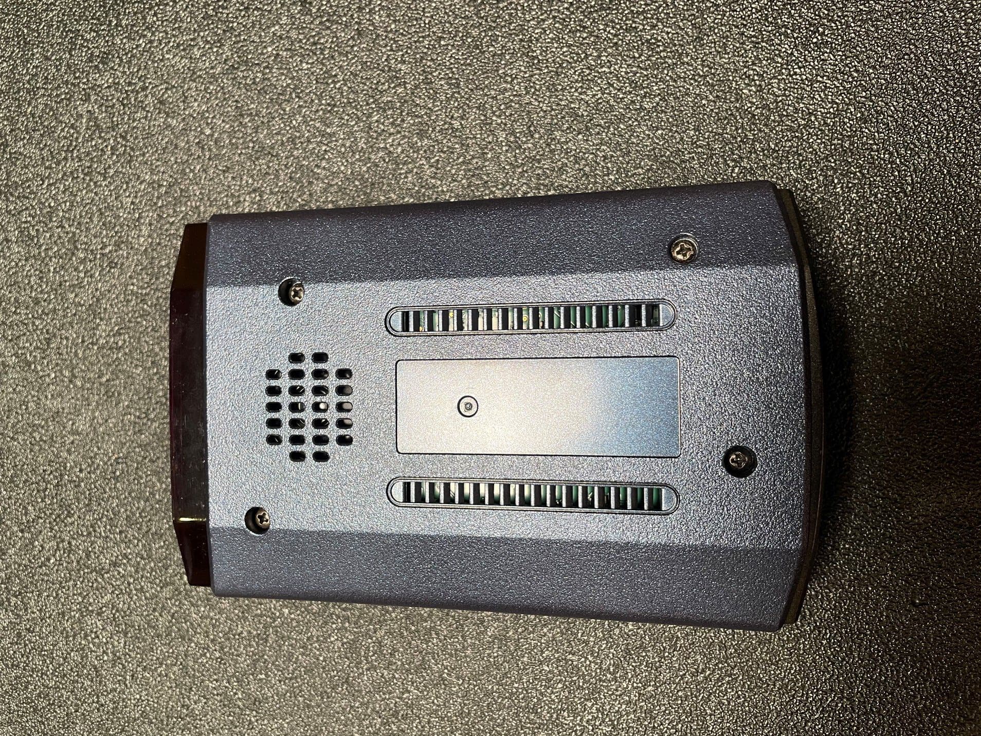
QKLM13
Mar 06, 2023Radar Detector with Bluetooth
Equipment Class
DTS - Digital Transmission System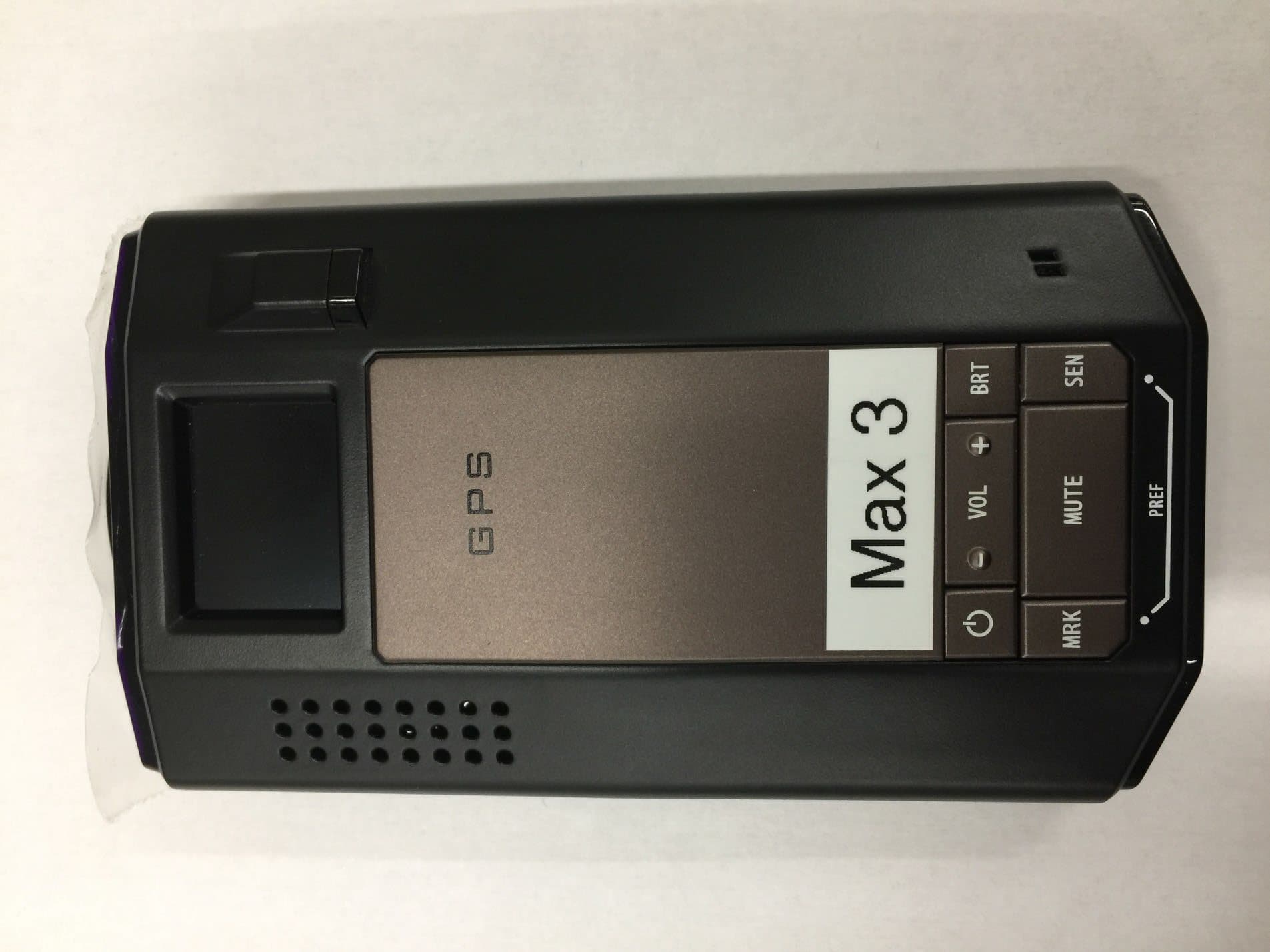
QKLMAX3V2
Dec 29, 2022Radar Detector with BLE
Equipment Class
DTS - Digital Transmission System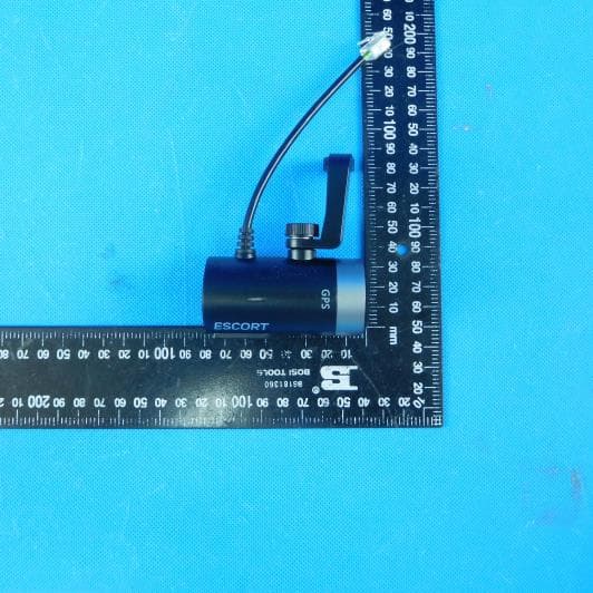
QKLDSM2
Jul 27, 2021DASH CAM
Equipment Class
DTS - Digital Transmission System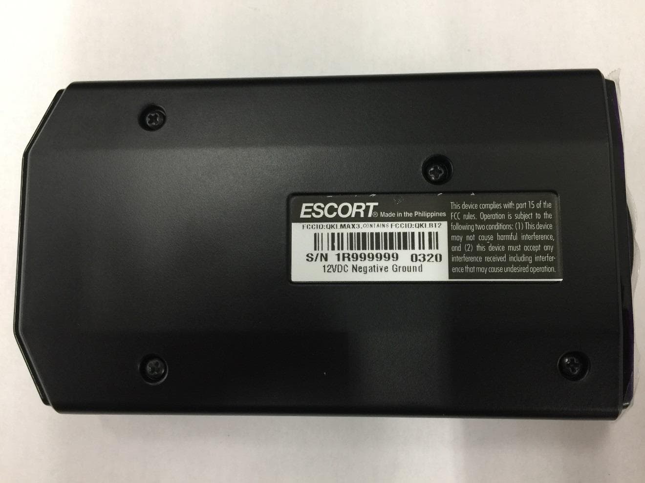
QKLMAX3
Jul 09, 2020ESCORT MAX 3
Equipment Class
CRD - Part 15 Radar Detector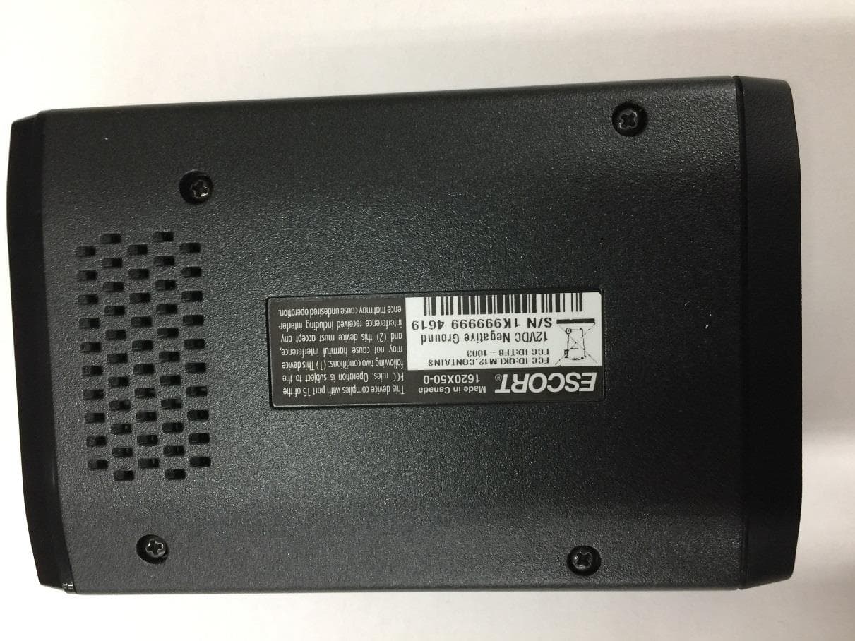
QKLM12
Jun 08, 2020ESCORT Redline 360c
Equipment Class
CRD - Part 15 Radar Detector