QKS-CX2-1100Non-Broadcast Transmitter
Sophia Communications, Inc.
Click to zoom
Application Details
- Equipment Class
- TNB - Licensed Non-Broadcast Station Transmitter
- Date of Grant
- Jul 02, 2003
- Application Purpose
- Original Equipment
- Date of Application
- Jul 02, 2003
- Equipment Note
- Non-Broadcast Transmitter
- Frequency Range
- 220.00000000 - 221.00000000
- Company
- Sophia Communications, Inc.
- Country
- United States
Documents & Files
Document Text
Text extracted from the exhibit documents filed with the FCC. Open a document above to read the original.
Users Manual
Exhibit 2 - Product Information SOPHIA Communications, Inc. QKS-CX2-1100 Page 2 - 1 2.1 Basic Model Description Equipment Category: Non - Broadcast Transmitter Radio Service: Private Land Mobile 220 - 222MHz, §90.701 Model number/name: CX2-1100 “DataHawk” Type of equipment: Base Station Transceiver Rated Supply Voltage: 117 V AC +/- 10% TX Frequency range: 220 - 221 MHz Frequency Tolerance: 0.1 ppm per §90.213 Channel spacing: 5 kHz per §90.203(k)(1) Power rating: 100 W PEP Transmitter duty cycle: 100% Modulation: QPSK Antenna: 50 ohm - coax connector 2.2 Information Required by §2.1033(c) 2.2.1 Applicant and Manufacturer Legal name: SOPHIA Communications, Inc. 8330 S. Madison St., Suite 15 Burr Ridge, IL 60527 Trade name: CX2 Technologies (same address as above) 2.2.2 FCC Identifier QKS-CX2-1100 2.2.3 Installation and Operating Instructions Please refer to Preliminary User Manual 2.2.4 Types of emission Authorized Bandwidth: 4 kHz per §90.209(b)(5) Emission Designator: 4K00D1D 2.2.5 Frequency Range Transmitter: 220 - 221 MHz Receiver: 221 - 222 MHz FCC Channels: 1 - 200 per §90.715 SOPHIA Communications, Inc. QKS-CX2-1100 Page 2 - 2 SOPHIA Communications, Inc. QKS-CX2-1100 Page 2 - 3 2.2.6 Operating Power Level 100 Watt PEP Power level is adjustable only at the factory or by service personnel. Please refer to Tune-up Procedure for adjustment means. 2.2.7 Maximum Power Rating: Per 47CFR §90.729(b) 2.2.8 DC voltages and currents in final RF amplifier: RF Power Module: 28 V DC, 4.0 A DC 2.2.9 Tune-up Procedure Please refer to separate Tune-up Procedure exhibit 2.2.10 Schematic Diagram and Circuit Description Please refer to separate Schematic Diagrams and Circuit Description exhibits. 2.2.11 Identification label Please refer to Equipment label exhibit. 2.2.12 Photographs Please refer to Photograph exhibit. 2.2.13 Modulation description Type: QPSK, 3205 symbols/sec, 6410 bps. Band limiting filter: Root Raised Cosine 0.20 excess BW factor. 2.2.14 Measured Data, §§2.1046 through 2.1057 Please refer to Report of Measurements. (Report also contains the test equipment list, statement on test procedure, frequency spectrum to be investigated and test supervisor’s statement.)
Users Manual
Exhibit 6 - Preliminary User’s Manual SOPHIA Communications, Inc. QKS-CX2-1100 Page 6 - 1 1 Introduction This manual describes the CX2 Technologies CX2-1100 DataHawk 100 Watt Base Station Transceiver. The CX2-1100 consists of two parts; the 1100R Receiver/Controller Box and the 1100T Transmitter Box. Together they provide base station capability for CX2 Networks, public or private, in the 220-222 MHz band. The CX2-1100 is designed to operate under the control of the CX2 Local Site Server (LSS). In normal use the LSS selects the channel, keys/dekeys the base station, and handles data input and output. Note: The 1100R and 1100T are intended to be used as a set only, in conjunction with a CX2 LSS and will not operate properly otherwise. Please contact CX2 for additional information about network configuration. The operation of this equipment is subject to FCC regulations regarding output power, frequency modulation and frequency accuracy as codified in 47CFR§2 and 47CFR§90. Correct setup and proper maintenance are essential elements in complying with these regulations and not interfering with other’s use of the radio spectrum. Please read this manual carefully, and have only qualified technical personnel perform setup and maintenance. Unauthorized modification of this equipment may void the user’s authority to operate it. This device complies with part 15 of the FCC rules. Operation is subject to the condition that this device does not cause harmful interference. This equipment has been tested and found to comply with FCC Part 15 Class B limits. These limits are designed to provide reasonable protection against harmful interference with other equipment. However, this is no guarantee that such interference will not occur in some particular installation. The CX2-1100 generates and radiates electromagnetic energy. Consequently it may affect other digital devices or receivers in the area. The user may take steps to ameliorate this interference should it occur, such as: • Make sure all equipment is properly grounded. • Increase the physical separation between the CX2-1100 and the affected device or devices. • Connect the CX2-1100 to a separate electrical outlet. • Reorient or relocate the receiving antenna of the affected device. • Should the problem persist, please contact CX2 for an evaluation. SOPHIA Communications, Inc. QKS-CX2-1100 Page 6 - 2 2 Safety Information This equipment radiates electromagnetic energy. The following measures are recommended to minimize exposure. Do Not Operate the transmitter when someone is within 1 meter (3 feet) of the antenna. Do Not Operate this equipment unless all RF connectors are properly connected and unused radiating ports are terminated. The following General Safety precautions should be observed at all times: This equipment operates with potentially dangerous voltages present within the case. Follow all procedures carefully to avoid electric shock hazards. Do Not Use damaged cables or connectors. Do Not Operate this equipment near electrical blasting caps. Do Not Operate this equipment in an explosive atmosphere. Make Sure this equipment is properly grounded. Note: The CX2-1100 should be installed and serviced only by qualified personnel. Improper installation or use could permanently damage the device and may cause injury or death. Note: There is a ten-minute delay from the time the CX2-1100 is powered up until the Transmitter can be keyed. This is to allow the frequency control circuits to reach a stable operating temperature. If it is necessary to overcome this delay for servicing the device, the RRM Configurator (See section 4.6) has that provision. Please use this override with care. SOPHIA Communications, Inc. QKS-CX2-1100 Page 6 - 3 3 Specifications Radio Service: Private Land Mobile 220-222MHz 47CFR§90 Subpart T Weight: 1100R –35 lbs. 1100T – 35 lbs. Model number/name: CX2-1100 “DataHawk” Type of equipment: Base Station Transceiver Mounting: 19” Rack Mount Rated Supply Voltage: 117 V AC +/- 10% TX Frequency range: 220-221 MHz RX Frequency range 221-222 MHz Frequency Tolerance: <0.1 ppm –30 to +50 C Channel spacing: 5 kHz Power rating: 100 W PEP Transmitter duty cycle: 100% Modulation: QPSK TX Antenna Connector: 50 ohm – Type N coax RX Antenna Connector 50 Ohm – Mini UHF SOPHIA Communications, Inc. QKS-CX2-1100 Page 6 - 4 4 Setup 4.1 Recommended Operating Environment The CX2-1100 is designed to be operated in a clean, dry location with ambient temperatures between -10 and +40 degrees C (+15 to +105 F). The environment should be free of excessive vibration and have adequate ventilation to insure proper equipment cooling. Prolonged exposure to excessive dust or moisture may permanently damage the device or its ancillary equipment. It is recommended that backup AC power be available to insure continued operation of the network if power is interrupted. 4.2 Inspection After unpacking the equipment perform a careful visual inspection of the 1100R, 1100T and all cables and connectors to be used in the installation. • Signs of external damage to the CX2-1100 could indicate internal damage as well. If there are indications of damage – Do Not continue with the installation. Return the damaged equipment to CX2 for evaluation and repair. • Pay particular attention to the connectors located in the rear of the devices, as shown in Figure 4.4 and 4.5. If damaged, these connectors must be repaired before use. Attached connectors are not user repairable – the 1100 must be returned to CX2 for repair. • Do not use damaged or improper connectors or cables in the installation of the base station. Such use may cause permanent harm to the CX2-1100 and could be dangerous. • Make sure all connectors are clean and free of grease or moisture. • Compare the equipment to the Figures in this manual to familiarize yourself with the name, location and use of the various connectors. 4.3 Mounting The CX2-1100 is to be mounted in the preassembled rack containing the duplexer, prea…
Text truncated - open the document above for the full version.
Cover Letter(s)
Date: June 25, 2003 To: FCC Equipment Authorization Branch and Elite Engineering Subject: Application for certification, FCC ID QKS-CX2-1100 and Request for Confidentiality per 47CFR §0.459 Ladies and Gentlemen: SOPHIA Communications, Inc. hereby submits in the form of the attached exhibits, information pursuant to obtaining a grant of Certification for its Model CX2-1100 “DataHawk” base station data transceiver under the trade name CX2 Technologies. SOPHIA Communications, Inc. respectfully requests that the following portions of its application for certification be kept confidential: Circuit Description, Schematic Diagrams, Block Diagrams. SOPHIA Communications, Inc. views the above named records to be proprietary trade secrets which it attempts to completely block from public view. Public release of those documents on the FCC website or other means of disclosure could harm its competitive position in the radio telemetry industry and would be detrimental to its potential business success. Sincerely, _____________________ Thomas P. Houck President SOPHIA Communications, Inc. SOPHIA Communications, Inc. QKS-CX2-1100
External Photos
Figure 5.1 External Front View SOPHIA Com m unications, Inc. QKS-CX2-1100 Page 5 - 2 Figure 5.2 External Back View (showing interconnections) SOPHIA Com m unications, Inc. QKS-CX2-1100 Page 5 - 3
ID Label/Location Info
Exhibit 1 - Identification Label SOPHIA Communications, Inc. QKS-CX2-1100 Page 1 - 1 Figure 1.1 Identification Label - CX2-1100R, Receiver / Control Assembly SOPHIA Com m unications, Inc. QKS-CX2-1100 Page 1 - 2 Figure 1.2 Identification Label - CX2-1100T, Transmitter Assembly SOPHIA Com m unications, Inc. QKS-CX2-1100 Page 1 - 3 SOPHIA Com m unications, Inc. QKS-CX2-1100 Page 1 - 4 DataHawkP/N: CX2-1100FCC ID:QKS-CX2-1100 2 5/8" 1" Figure 1.3 Identification Label - CX2-1100
Internal Photos
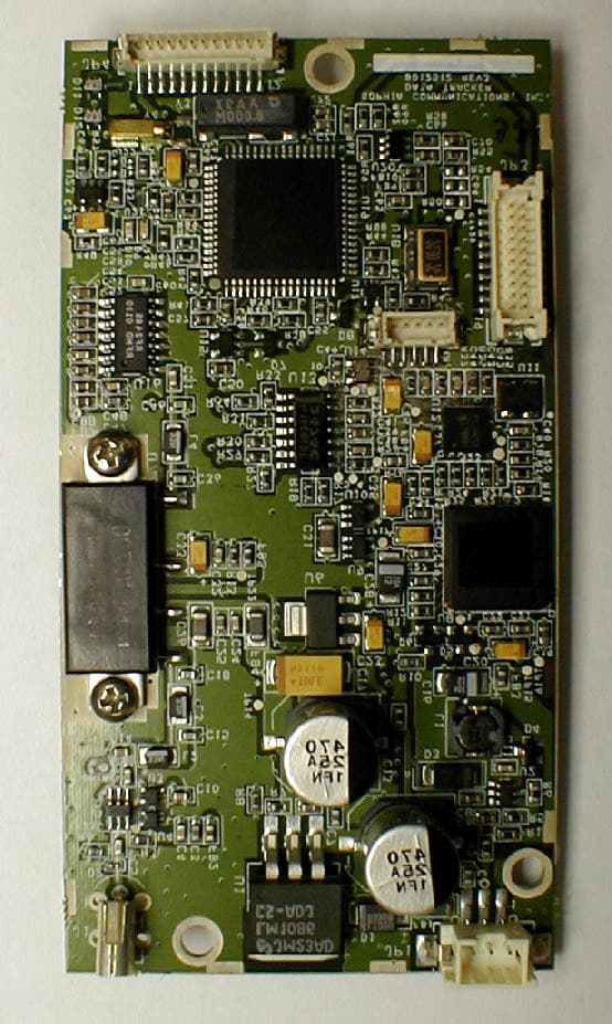
Exhibit 5 - Photographs SOPHIA Communications, Inc. QKS-CX2-1100 Page 5 - 1 Figure 5.3 Internal Top View - CX2-1100R (Receiver/Control) SOPHIA Com m unications, Inc. QKS-CX2-1100 Page 5 - 4 Figure 5.4 Internal Top View - CX2-1100R (Receiver/Control) Controller Board Detail SOPHIA Com m unications, Inc. QKS-CX2-1100 Page 5 - 5 Figure 5.5 Internal Bottom View - CX2-1100R (Receiver/Control) SOPHIA Com m unications, Inc. QKS-CX2-1100 Page 5 - 6 SOPHIA Com m unications, Inc. QKS-CX2-1100 Page 5 - 7 Figure 5.6 Internal Top View - CX2-1100T (Transmitter)
Parts List/Tune Up Info
Exhibit 10 - Tune-up Procedure SOPHIA Communications, Inc. QKS-CX2-1100 Page 10 - 1 10.1 Equipment Required Instrument Manufacturer and Model RF Power Attenuator Bird 100A-MFN-30 Power Meter Agilent E4416A Peak and Average Power Sensor Agilent E9321A Vector Signal Analyzer HP 89441A Frequency Counter 1.5GHz Agilent 53181A Universal Counter 225MHz Agilent 53131A Frequency Standard (GPS) TrueTime Model XL-DC RF Signal Source Agilent E4437B Personal Computer Compaq Armada 7400 10.2 Software Tools Required Base Station Configuration Tool - Version 1.0.0.84 or higher 10.3 Test Setup Base Station Receiver & Controller Base Station Transmitter IF Input = 10.273MHz Ref. Input = 10.275MHz 12 VDC Transmitter On/Off Transmitter Key Serial Bus CX2 - 1100RCX2 - 1100T 117 VAC Pwr Serial Antenna 117 VAC Computer Terminal Pwr RF Attenuator 60 dB Including Cable Losses Spectrum Analyzer Figure 10.1 Tune-up Procedure Test Setup Block Diagram Peak Wattmeter Frequency Counter GPS - Based Frequency Standard SOPHIA Communications, Inc. QKS-CX2-1100 Page 10 - 2 10.4 Procedure 10.4.1 Preliminary The tune-up procedure consists of the following steps: Adjustment of transmitter frequency reference circuits. Adjustment of transmitter power output. Connect the equipment as shown in figure 10.1. The total RF attenuator loss, including all cable losses, should be measured by suitable means. Adjust the Vector Spectrum analyzer as follows: Digital demodulation mode, QPSK, 3.205125 symbols, root raised cosine filter w/alpha of 0.2 Center frequency 220.4975 MHz, 10 kHz span. Set split display, four quadrants, show I&Q plane, error vector magnitude with frequency/phase error, eye pattern. Adjust the wattmeter as follows: Power up and run calibration routine. Recall settings for reading peak power at 220.5 MHz. Verify that display offset equals attenuator plus cable loss (60 dB nominal). Set for normal trigger. Adjust the frequency Counter as follows: Power up, instrument will use default settings. Select measure frequency channel 1. Select external reference. Input impedance to 50 ohms, AC coupling. Gate time 0.5 sec. In order to perform these adjustments it is necessary to utilize a computer terminal running the latest version of CX2 Technologies Base Station Configuration Tool. Software Tool Setup 1. Using a DB-9F to DB-25F null modem cable, connect serial port COM1 on the computer terminal to ACC2 port on the CX2 - 1100R. 2. Run the RRMCONFIG executable file. 3. Press the Password button and type in the required password. 4. Press the Configure button; a “Configure” window will pop up. 5. Press the “Configure Serial Port” button. 6. A “SerComm Control Properties” window will pop up. SOPHIA Communications, Inc. QKS-CX2-1100 Page 10 - 3 7. Using this window, set the serial port to COM1, 38400 bps, 8 data bits, 1 stop bit, no parity. Handshaking disabled, time-out at 2 ms each. 8. Press the “Connect” button, the message “Communication with serial port is established on COM1” will show up if configuration was successful. Press the “Ok” button. Press the “Exit” button to exit the “Configure” window. 9. A scrolling green rectangle on the top of the screen will signal proper communication with the Base Station, a red one will signal a loss of communication with the unit. Figure 10.2 Base Station Configuration Tool - Main Screen SOPHIA Communications, Inc. QKS-CX2-1100 Page 10 - 4 Figure 10.3 Base Station Configuration Tool - Serial Port Properties With the computer terminal “talking” to the base station, perform the following steps to program the operating frequency: 10. Press the Configure button; a “Configure” window will pop up. 11. Press the “Configure Chassis Parameters” button. 12. A “Configure Chassis Parameters” window will pop up. 13. Using this window set the receiver channel to # 300 - 221.4975 MHz, and the transmitter channel to # 100 - 220.4975 MHz. Press apply to make the changes effective. The corresponding frequency values will be shown below each of the channel numbers. 14. Press the “Ok” button. Press the “Exit” button to exit the “Configure” window. 15. Press the “Refresh” button at the bottom right side of the main screen; the selected channel and frequency should be displayed under the Receiver and Transmitter Chassis Status windows. Figure 10.4 Base Station Configuration Tool - Channel Selection SOPHIA Communications, Inc. QKS-CX2-1100 Page 10 - 5 10.4.2 Frequency Calibration Two different frequency adjustments are required, one for the MBSO and the other for the RRM reference. RRM Reference This alignment requires direct connection of the Frequency Counter to the Transmitter IF Output of the CX2 - 1100R. The equipment should be fully warmed up for a minimum of 30 min before attempting this adjustment. Using the Base Station Configuration Tool, select the “Out of Phase Test Tone” on the Modulator DSP dialog. This will generate a 1602.5 Hz test tone that will be used to adjust the reference. Using potentiometer R50, adjust the frequency output to 10,271,397.5 Hz. Select “Modulator DSP On” to exit the test mode. MBSO Connect the equipment as shown in figure 10.1; select the Frequency Counter. The equipment should be fully warmed up for a minimum of 30 min before attempting this adjustment. Using the Base Station Configuration Tool set the output level by adjusting the scrolling slide at the bottom of the main screen to -26.81 dBm and press the “Set” button. It is easier to fly and click the mouse cursor over the adjustment “lever” and then use the right and left arrows to adjust the power in increments of 0.75 dB. Using the Base Station Configuration Tool, select the “Out of Phase Test Tone” on the Modulator DSP dialog. This will generate a test tone that will be used to adjust the reference. Key the transmitter and measure the frequency output of the base station on the frequency counter. The nominal reading - because of the 1602.5Hz test tone - should be 220…
Text truncated - open the document above for the full version.
RF Exposure Info
Exhibit 9 - RF Exposure Information SOPHIA Communications, Inc. QKS-CX2-1100 Page 9 - 1 SOPHIA Communications, Inc. QKS-CX2-1100 Page 9 - 2 9.1 Actions that may have a significant environmental effect, for which Environmental Assessments (EAs) must be prepared §1.1307(b) Not Applicable As the output power of this device does not exceed 100 W PEP, no evaluation is required. Reference §1.1307(b)(1) “However, a determination of compliance with the exposure limits in §1.1310 or §2.1093 of this chapter (routine environmental evaluation), and preparation of an EA if the limits are exceeded, is necessary only for facilities, operations and transmitters that fall into the categories listed in table 1, or those specified in paragraph (b)(2) of this section. All other facilities, operations and transmitters are categorically excluded from making such studies or preparing an EA, except as indicated in paragraphs (c) and (d) of this section”. Table 1 - Transmitters, Facilities and Operations Subject to Routine Environmental Evaluation Service (title 47 CFR rule part) Evaluation required if Non-building-mounted-antennas: Height above ground level to the lowest point of the antenna < 10m and total power of all channels > 1000 W ERP (1640 W EIRP) Private Land Mobile Radio Services Specialized Mobile Radio (Part 90) Building-mounted-antennas: Total power of all channels > 1000 W ERP (1640 W EIRP)
Test Report
Exhibit 7 - Report of Measurements SOPHIA Communications, Inc. QKS-CX2-1100 Page 7 - 1 7.0.1 General Measurement Procedure §2.947, 2.1041, 2.1057 Transmitter testing was conducted using generally accepted engineering laboratory techniques and in accordance with TIA/EIA TSB78 titled Land Mobile Linear Analog Modulation Communications Equipment Measurement and Performance Standards (equivalent to TIA/EIA 603). ANSI C63.4 also applies for spurious radiation testing. Because the transmitter tuning range spans only ½ percent of the output frequency range, all transmitter tests were conducted at the center of the range on FCC channel 100 for base stations, i.e., 220.4975 MHz. Frequencies investigated during the Spurious Radiation at Antenna Terminals Test were in the range 4 MHz to 2.205 GHz representing the lowest clock frequency and the Test Radio’s tenth harmonic frequency, respectively. Frequencies investigated for the Spurious Radiation Test were from 30 MHz to 2.205 GHz. The RF network analyzer and the RF signal source were used in checking the attenuation of the RF attenuator and associated coax connecting cables and adapters over the frequency search range. Additional procedural details are presented along with the specific procedures above. 7.0.2 Measurement Facilities All but the spurious radiation testing was conducted at the applicant’s engineering facilities in Burr Ridge, IL. Elite Electronic Engineering personnel using their own equipment at their FCC registered 3-meter test site in Downers Grove, IL conducted the spurious radiation testing. SOPHIA Communications, Inc. QKS-CX2-1100 Page 7 - 2 7.0.3 Equipment List §2.947(d) Instrument Manufacturer and Model Next Cal. Due Variable Isolated AC Supply Heathkit Model IP5220 NA RF Power Attenuator Bird 100A-MFN-30 NA Power Meter Agilent E4416A 5/14/04 Peak and Average Power Sensor Agilent E9321A 5/9/04 Vector Signal Analyzer HP 89441A 5/14/04 Frequency Counter 1.5GHz Agilent 53181A NA Universal Counter 225MHz Agilent 53131A 5/13/04 Frequency Standard (GPS) TrueTime Model XL-DC NA Temperature Chamber Tenney Jr. NA Temperature Controller Watlow Series 942 NA Digital Voltmeter Fluke 187 NA RF Signal Source Agilent E4437B 8/17/03 Personal Computer Compaq Armada 7400 NA SOPHIA Communications, Inc. QKS-CX2-1100 Page 7 - 3 7.1 RF Power Output §2.1046 Measured RF Power Output 100 W PEP Additional Requirements : Limitations on power and antenna height, §90.729 (a) “The permissible effective radiated power (ERP) with respect to antenna heights for land mobile, paging, or fixed stations transmitting on frequencies in the 220 - 221 MHz band shall be determined from the following Table. These are maximum values and applicants are required to justify power levels requested”. ERP vs. Antenna Height Table 2 Antenna height above average terrain (HAAT), meters Effective radiated power, watts 1 Up to 150 500 150 to 225 250 225 to 300 125 300 to 450 60 450 to 600 30 600 to 750 20 750 to 900 15 900 to 1050 10 Above 1050 5 1 Transmitter PEP shall be used to determine ERP 2 These power levels apply to stations used for land mobile, paging, and fixed operations. Emission Masks, §90.210 (f) Complies with emission mask §90.210 (f) during power output test. Please refer to 7.3 Occupied Bandwidth §2.1049 Procedure : The Test Radio was previously tuned up on 220.4975 MHz in accordance with the Tune-up procedure. The equipment was connected as shown in Figure 7.1 below. Total RF attenuation between the Test Radio antenna terminals and the wattmeter was measured to be 48.8 dB (including cable losses). Wattmeter power offset was adjusted by an equal and opposite amount so that the wattmeter would indicate power in peak watts when adjusted as per the manufacturer’s instructions. SOPHIA Communications, Inc. QKS-CX2-1100 Page 7 - 4 A computer terminal was used to feed a stream of data to obtain a continuous pseudo-random QPSK test modulation, as well as controlling the transmit key. The selected modulation represents the maximum amplitude and symbol rate conditions that occur during regular operation. After recording the peak watts reading, the wattmeter was removed and the spectrum analyzer was attached in its place. The spectrum analyzer was set initially to 100kHz span and 10kHz resolution bandwidth (i.e., 2.5 times the authorized bandwidth) and peak hold. The reference level of the spectrum analyzer was then set to the peak output power of the Test Radio (representing +50 dBm = 100W). The spectrum analyzer was then adjusted to 10kHz span and 100Hz resolution bandwidth and the plot of occupied band was obtained. See Section 7.3. Base Station Receiver & Controller Base Station Transmitter IF Input = 10.273MHz Ref. Input = 10.275MHz 12 VDC Transmitter On/Off Transmitter Key Serial Bus CX2 - 1100RCX2 - 1100T 117 VAC Pwr SerialAntenna 117 VAC Computer Terminal Pwr RF Attenuator 48.8 dB Including Cable Losses Notch Filter Peak Wattmeter or Spectrum Analyzer Figure 7.1 Test Setup Block Diagram 7.2 Modulation Characteristics §2.1047 This test is not applicable. Application of external data does not affect the modulation level. SOPHIA Communications, Inc. QKS-CX2-1100 Page 7 - 5 7.3 Occupied Bandwidth §2.1049 Limit, §90.210(f) Result Emission Mask F Complies, see Fig. 7.2 Emission Mask §90.210(e)(4) : The reference level for showing compliance with the emission mask shall be established using a resolution bandwidth sufficiently wide (usually two to three times the channel bandwidth) to capture the true peak emission of the equipment under test. In order to show compliance with the emission mask up to and including 50kHz removed from the edge of the authorized bandwidth, adjust the resolution bandwidth to 100Hz with the measuring instrument in peak hold mode. A sufficient number of sweeps must be measured to insure that the emission profile is developed. If video filtering is used, its bandwidth must not be less than the instrument resolution bandwidth. For emissions bey…
Text truncated - open the document above for the full version.
Test Report
Exhibit 8 - Spurious Radiation Test Data SOPHIA Communications, Inc. QKS-CX2-1100 Page 8 - 1 ETR 32316-02 DATA SHEET SOPHIA Communications, Inc. QKS-CX2-1100 Page 8 - 2 MANUFACTURER : SOPHIA MODEL : CX2 1100 DATAHAW S/N : Tx EB 1192, Rx EA 1053 SPECIFICATION : FCC-90 OPEN FIELD SPURIOUS RADIATED EMISSIONS DATE : MAY 29, 2003 NOTES : 100 WATTS PEAK OUTPUT INTO 50 OHMS : TEST DISTANCE IS 3 METERS MTR MATCHED ANT CABLE ERP MIN FREQ. ANT RDG SIGNAL GAIN FAC TOTAL ATTN ATTN (MHz) POL (dBuV) dBm dB dB dBm dB dB 441.0 H 14.3 -63.9 1.5 -65.4 115.4 75 441.0 V 18.3 -57.9 1.5 -59.4 109.4 75 661.5 H 10.5 -59.6 2.0 -61.6 111.6 75 661.5 V 15.0 -60.5 2.0 -62.5 112.5 75 882.0 H 4.5 AMB -66.5 2.5 -69.0 119.0 75 882.0 V 5.3 AMB -64 2.5 -66.5 116.5 75 1102.5 H 55.0 -55.3 4.4 2.9 -53.8 103.8 75 1102.5 V 54.1 -58.3 4.4 2.9 -56.8 106.8 75 1323.0 H 45.7 AMB -58.1 5.4 3.2 -55.9 105.9 75 1323.0 V 48.2 AMB -58.0 5.4 3.2 -55.8 105.8 75 1543.5 H 46.0 AMB -65 6.1 3.5 -62.4 112.4 75 1543.5 V 47.8 AMB -60 6.1 3.5 -57.4 107.4 75 1764.0 H 46.4 -55.1 6.2 3.8 -52.7 102.7 75 1764.0 V 48.4 -59.5 6.2 3.8 -57.1 107.1 75 1984.5 H 50.3 -55.9 6.5 4.1 -53.5 103.5 75 1984.5 V 49.4 -50.2 6.5 4.1 -47.8 97.8 75 2205.0 H 50.6 -45.8 6.6 4.3 -43.5 93.5 75 2205.0 V 54.5 -50.3 6.6 4.3 -48.0 98.0 75 CHECKED BY: Mark E. Longinotti
Contact Information
Applicant
John F Cleveland(Staff Engineer)
Test Firm
Elite Electronic Engineering Co.Daniel Crowder
Technical Specifications
| # | Rule Parts | Frequency Range | Power Output | Emission | Tolerance |
|---|---|---|---|---|---|
| 1 | 90 | 220 MHz - 221 MHz | 100 W | 4K00D1D | 0.1000000000 ppm |
Other Applications from Sophia Communications, Inc.
QKSCD1201
Sep 11, 2002Non-Broadcast Transmitter
Equipment Class
TNB - Licensed Non-Broadcast Station Transmitter