QKSCD1201Non-Broadcast Transmitter
Sophia Communications, Inc.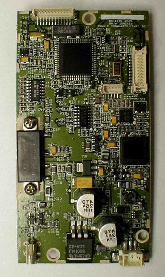
Click to zoom
Application Details
- Equipment Class
- TNB - Licensed Non-Broadcast Station Transmitter
- Date of Grant
- Sep 11, 2002
- Application Purpose
- Original Equipment
- Date of Application
- Sep 11, 2002
- Equipment Note
- Non-Broadcast Transmitter
- Frequency Range
- 221.00000000 - 222.00000000
- Company
- Sophia Communications, Inc.
- Country
- United States
Documents & Files
Document Text
Text extracted from the exhibit documents filed with the FCC. Open a document above to read the original.
Users Manual
1 User’s Manual for DataTracker - Model CD1201 4 Sept 2002 Preliminary Draft Manufactured By: 8330 South Madison Street Burr Ridge, IL 60527 (630) 323-6110 www.cx2tech.com 2 Product Description: Caution: Please read Important Information to the User later in this manual. CX2’s model CD-1201, “DataTracker” is a subscriber end-unit radio transceiver designed specifically for communication within the CX2 wireless data network. The CX2 network provides point-to-multipoint, two-way, over-the-air data communications between a DataTracker and the single CX2 base station to which it is registered. In the CX2 network, over-the-air data communication is managed using a proprietary version of slotted- aloha, half-duplex, packet protocol. The DataTracker is not capable of direct RF communications with other subscriber end-units. The CD-1201 transceiver can operate in half-duplex mode on any of the 200, 5 kHz spaced channels specified by the FCC in the in the 220 to 222 MHz band. The CX2 Base-Station operates in full-duplex mode, with the Base Station transmitter always on-the-air. A transmission from a DataTracker to the Base Station occurs in synchronous, burst mode within specific time-slots as directed by the base station. The DataTracker must be receiving and locked to the base station before it can transmit. An annotated photograph of the CD-1201 DataTracker is shown below as Figure 1. Detailed specifications for the CD-1201 are included in a later section of this document. Mounting Holes Antenna Jack Power Connector Serial Data Connector For Factory Use Only Figure 1: Top View of the DataTracker Model CD-1202 Installation: Mounting and Interconnection (Refer to Figure 1): Caution: Do not attach wiring or components to any points other than the specific connectors described below. 3 Mounting: As shown in the figure there are three 0.15”diameter mounting holes. The DataTracker board should be mounted on ¼” or higher metal or plastic standoffs using #4, #5 or #6 machine screws or studs. Use care to insure that any metal standoffs, screw heads, nuts or washers used to mount the DataTracker do not short to adjacent components or board traces that are not a part of the ground circuit on the PC board. Antenna Connector: The female coaxial RF antenna jack (Taiko-Denki type: TMP-K01X-A1) is shown in the upper right. The mating female connector is the Taiko-Denki type: TMP-K01X- A1). A suitable ¼-wave or ½-wave vertically polarized 50-Ohm antenna and feeder must be connected to this point before the radio is powered on. Caution: The antenna radiating element should be mounted such that no person comes within 20 cm. (8 inches) of the antenna during normal operation. Example: Center of car roof. While the DataTracker is not overly sensitive to high VSWR conditions at the antenna port, prolonged transmissions without a matching 50-ohm resistive load could damage the transmitter components. Power Connector : The proprietary 3-pin power connector is shown in lower right. A mating 3- pin plug with 6” power leads is provided by CX2 with each DataTracker. The three power leads should be connected as follows: Pin 1, Black Lead: - VDC and chassis ground Pin 2, Yellow Lead: Device Enable, connect to +12 VDC to Enable Pin 3, Red Lead: + 12 VDC (nominal) Serial Data Connector: The proprietary, 12-pin data connector is shown to the upper left. A mating 12-pin plug with 6” leads is provided by CX2 with each DataTracker. The data leads should be connected as follows: Pin 1 Serial Port A, TX Data Pin 2 Serial Port A, RX Data Pin 3 Serial Port B, TX Data Pin 4 Serial Port B, RX Data Pin 5 Reserved for future use Pin 6 Reserved for future use Pin 7 Reserved for future use Pin 8 Reserved for future use Pin 9 Reserved for future use Pin 10 Reserved for future use Pin 11 Reserved for future use Pin 12 Serial Data Common and Chassis Ground Other: The two jacks shown to the bottom left in Figure 1 are for factory use only. 4 Operation: Text for this section TBD. Detailed Specifications General: Model: CD-1201 Type: 220 MHz, Synthesized, Two-Way, Half Duplex, Split-Frequency, 5 kHz Channels Using a Proprietary Air-Link Protocol Operating in Synchronous Burst Mode Intended Payload: Balanced, Two-Way, Store and Forward Data Messages in Packets Up to 2000 Bytes in Length Antenna Jack: 50-Ohm Coaxial Compliance: FCC Parts 2, 15, 90 FCC ID QKS-CD1201 Digital Configuration: Processors: 100 MIPS DSP and Separate 8-bit RISC Micro Controller with 128KB Flash and 4KB SRAM Data Interface: Two TTL Level Proprietary Serial Ports Transmitter: Type: DSP Modulator with Linear Up-Converter and Amplifier Frequency Range: 221.0025 – 221.9975 MHz. (All 200 FCC Channels) Channel Spacing: 5 kHz Frequency Stability: 0.1 ppm, -30 to +60 Degrees C when locked to the base station, otherwise 1.5 ppm. -30 to +60 Degrees C. Note: During normal operation the Transmitter cannot be keyed unless it is locked to the base station. Modulation Type: QPSK Occupied Bandwidth: 4 kHz (Meets the FCC Mask for 5 kHz Channel Spacing, as per Part 90, Section 90.210(f) Output Impedance: 50 Ohms, Coaxial RF Power Output: 1 Watt PEP 5 Transmit Duty Cycle: 30%, Maximum Spurious Output: -55 dB. Complies with 47CFR 90.210(F) Transmitter Keying: Automatic, Processor Controlled Receiver: Type: Linear LNA and Down-Converter with DSP Demodulator Frequency Range: 220.0025 – 220.9975 MHz. (All 200 FCC Channels) Channel Spacing: 5 kHz Frequency Stability: 0.1 ppm, -30 to +60 Degrees C when locked to the base station, otherwise 1.5 ppm. -30 to +60 Degrees C. Input Impedance: 50 Ohms, Coaxial Sensitivity: 12 dB SINAD @ -118 dBm Intermodulation: -60 dB Selectivity: -40 dB Typical at Adjacent Channel Bandwidth: 4 kHz Primary Power: Voltage: 13.8 VDC (Nominal), Negative Ground (Operable from 11 to 16.8 VDC) Current (Typical): Receive and Standby 110 mA; Transmit 2.0A @ 13.8 VDC Connector: Proprietary, 3 Pins Circuit Protection: Internal Reverse Voltage Protection Physical & Environmental: O…
Text truncated - open the document above for the full version.
Cover Letter(s)
Sophia Communications, Inc. QKS-CD1201 Date: September 5, 2002 To: FCC Equipment Authorization Branch and Elite Engineering Subject: Application for Certification, FCC ID QKS-CD1201 And Request for Confidentiality per 47CFR §0.459 Ladies and Gentlemen: Sophia Communications, Inc. hereby submits in the form of the attached exhibits, information pursuant to obtaining a grant of Certification for its Model CD-1201 DataTracker mobile data transceiver under the trade name CX2 Technologies. Sophia Communications, Inc. respectfully requests that the following portions of its application for certification be kept confidential: Circuit Description, Schematic diagrams, Block diagrams, Parts list. Sophia Communications, Inc. views the above named records to be proprietary trade secrets which it attempts to competely block from public view. Public release of those documents on the FCC website or other means of disclosure could harm its competitive position in the radio telemetry industry and would be detrimental to its potential business success. Sincerely, Thomas P. Houck __________________ Thomas P. Houck President Sophia Communications, Inc. Sophia Communications, Inc. QKS-CD1201 List Of Exhibits Exhibit 1. Identification Label Exhibit 2. Product Information Exhibit 2A. Circuit Description Exhibit 3. Schematic Diagrams Exhibit 4. Block Diagrams Exhibit 5. Photographs Exhibit 6. Preliminary User Manual Exhibit 7. Report of Measurements Exhibit 8. Spurious Radiation Test Data Exhibit 9. RF Exposure Info Exhibit 10. Parts List Exhibit 11. Tune-up Procedure
External Photos
Sophia Communications QKS-CD1201 Page 5-1 Exhibit 5. Photographs Figure 5.1 Top View Sophia Communications QKS-CD1201 Page 5-2 Figure 5.2 Bottom View (Shields Removed)
ID Label/Location Info
Sophia Communications, Inc. QKS-CD1201 Page 1-1 Exhibit 1. Identification Label Figure 1.1 Photograph of Model CD-1201 Equipment Label
Internal Photos
Sophia Communications QKS-CD1201 Page 5-1 Exhibit 5. Photographs Figure 5.1 Top View Sophia Communications QKS-CD1201 Page 5-2 Figure 5.2 Bottom View (Shields Removed)
Parts List/Tune Up Info
Sophia Communications, Inc. QKS-CD1201 Page 11-1 Exhibit 11. Tune-up Procedure 11.1 Equipment Required Instrument Manufacturer and Model Power Supply Astron VS-12M or RM-35M RF Power Attenuator Bird 100A-MFN-30 Power Meter Agilent E4416A Peak and Avg Power Sensor Agilent E9321A Vector Signal Analyzer HP 89441A Frequency Standard (GPS) TrueTime Model XL-DC Digital Voltmeter Fluke 187 Personal Computer Dell Inspiron 3000 11.2 Setup Figure 11.1 Test Setup for Tune-Up Procedure 11.3 Procedure: 11.3.1 Preliminary The Tune-up Procedure consists of transmitter frequency and power output calibration. Connect equipment as shown in the Test Setup diagram above using Vector Network Analyzer first. Total RF cable and RF attenuator loss should previously be verified by suitable means. Connect Frequency Standard (not shown) to Vector Network Analyzer. Power Supply 13.8 Vdc Test Radio Pwr Ant Serial RF Power Attenuator -30.0 dB incl. cables Power Meter or Vector Network Anal yzer PC Terminal DC Voltmeter Sophia Communications, Inc. QKS-CD1201 Page 11-2 1. Set computer terminal program for 9600-8-N-1 direct to com port. 2. Power radio. Wait for logon message to complete. Hit enter on pc to get menu. 3. Switch menu: Turn off auto scan and auto registration. 4. Main Menu: Select Channel 100. 5. Z Menu: Select Test modulation, QPSK 6. Z Menu: Set codec modulation level to –7 dB. 7. R Menu: Check power level value is set at 240. 8. R Menu: Set AFC to 1850 initially. 9. Adjust Vector Network Analyzer: Frequency: 221.4975 MHz. Set for Demodulation as follows: Mode: QPSK Symbol Rate: 3205.128 symbols per sec. Filter: Root Raised Cosine, alpha = 0.25 Display: Set to list show carrier frequency error and error vector magnitude. 11.3.2 Frequency Calibration 1. R Menu: Key Transmitter and measure carrier frequency error on vector analyzer. 2. R Menu: If necessary, adjust manual AFC control until carrier frequency error magnitude is 10 Hz or less on the vector network analyzer. 3. R menu: Unkey transmitter 4. Disconnect Vector Network Analyzer and connect Peak Wattmeter and its sensor in place at the output of the attenuator. 11.3.3 Power Output Calibration 1. Wattmeter: Power up and run calibration routine. Recall settings for reading peak power at 221 MHz. Verify that display offset equals the cable and attenuator loss (normally 30 dB). Set for normal trigger. 2. R Menu: Key transmitter and measure peak power. Value should be 1.0 W peak plus or minus 0.1 Watt. Unkey transmitter. 3. Z menu: If necessary, adjust codec output modulation level up or down and repeat step 2 until the power level is as specified. ____________________________ END ___________________________
RF Exposure Info
Sophia Communications, Inc. QKS-CD1201 Page 9-1 Exhibit 9. RF Exposure Information 9.1 Determination of Need for Routine Environmental Evaluation for RF Exposure Reference: 47CFR §§2.1091, 1.1310 and FCC OET65. Applicability: Our CD-1201 data transceiver fits the mobile device category described in §2.1091(b). It is used with an externally mounted antenna and is not to be worn on the body. Mobile devices that are subject to routine environmental evaluation for RF exposure are delineated in §2.1091(c). It is our view that the CD-1201 can be categorically excluded from routine environmental evaluation for RF exposure evaluation because it falls outside two of the subject equipment categories listed in §2.1091(c): 1. As shown further below, the unit’s ERP when used with a dipole type antenna and averaged over time is less than the 1.5 W ERP limit for units operating below 1.5 GHz. 2. The unit is subject to operation under Part 90 but it is not a Specialized Mobile Radio per the definition in §90.7. 9.2 Separation Distance Calculation The ERP and worst-case separation distance for uncontrolled exposure is calculated based on the information provided by FCC OET65. Max. duty ratio of transmitter: D= 30 % Transmitter max power output: P= 1000 mW PEP Max. gain of mobile antenna: G= 1.64 x isotropic (car top 1/4 wave) Effective Radiated Power: ERP= 0.492 W (Source-based time averaging) Max. power density 30-300 MHz S= 0.2 mW/cm^2 (30-300 MHz uncontrolled) S=PGD/(4PiR^2) R=0.5(PGD/(PiS))^0.5 R= 14.0 cm separation inches=cm/2.54 R= 5.5 in. separation
Test Report
Sophia Communications, Inc. QKS-CD1201 Page 7-1 Exhibit 7. Report of Measurements 7.1 RF Power Output §2.1046 Mobile Limit, §90.729(b) Measured RF Power Output 50 W ERP 1.0 W PEP Additional requirement: Complies with emission mask §90.210(f) during power output test. Please refer to the Occupied Bandwidth Plot, Figure 7.2. Procedure: The Test Radio was previously tuned up on 221.4975 MHz in accordance with the Tune-up Procedure. The equipment was connected as shown in Figure 7.1 below. Total RF attenuation between Test Radio antenna terminals and wattmeter was measured at 30 dB. Wattmeter power offset was adjusted by an equal and opposite amount so that the wattmeter would indicate power in peak watts when adjusted per the manufacturer’s instructions. A computer terminal was used to select internally generated continuous pseudo-random QPSK test modulation and it also controlled the transmit key. The selected modulation represents the maximum amplitude and symbol rate condition which occurs during regular operation. After recording the peak watts, the wattmeter was removed and spectrum analyzer was attached in its place. The spectrum analyzer was set initially to 10 kHz resolution bandwidth (i.e., 2.5 times the authorized bandwidth), 0 dBm ref. level (representing 30 dBm = 1W) and peak hold to corroborate that the peak emission was at 0 dBm when the transmitter was keyed. This is evidenced in Fig. 7.3. The spectrum analyzer was then adjusted to 100 Hz resolution bandwidth and 10 kHz span and the plot of occupied bandwidth was obtained. See Section 7.3. 7.2 Modulation Characteristics §2.1047 This test is not applicable. Application of external data does not affect modulation level. Power Supply 13.8 Vdc Test Radio Pwr Ant Serial RF Power Attenuator -30.0 dB incl. cables Peak Wattmeter Or Spectrum Anal yzer PC Terminal Figure 7.1 Test Block Diagram ETR No. 31269-01 DATA SHEET MANUFACTURER : SOPHIA COMMUNICATIONS MODEL : CD1201 S/N : 20 SPECIFICATION : FCC-90 OPEN FIELD SPURIOUS RADIATED EMISSIONS DATE : AUGUST 6, 2002 NOTES : TRANSMIT AT MHz (FULL POWER) INTO 50 OHMS : TEST DISTANCE IS 3 METERS Mtr. Minimum Freq. Ant Rdg. ERP Attenuatio n Attenuatio n MHz Pol dBuV dBm dB dB 443.0 H 21.4 -61.2 94.2 55 V 30.7 -62.6 95.6 55 664.0 H 32.5 -58.6 91.6 55 V 35.4 -59.3 92.3 55 886.0 H 27.8 -56.7 89.7 55 V 30.6 -55.7 88.7 55 1107.0 H 60.9 -58.7 91.7 55 V 65.8 -56.6 89.6 55 1329.0 H 60.1 -58.3 91.3 55 V 62.5 -58.4 91.4 55 1550.0 H 53.9 -52.8 85.8 55 V 54.6 -55.4 88.4 55 1772.0 H 52.7 -56.8 89.8 55 V 55.5 -56.7 89.7 55 1993.0 H 45.9 -53.3 86.3 55 V 44.7 -54.4 87.4 55 2215.0 H 41.9 -54.8 87.8 55 V 42.9 -55.0 88.0 55 Checked by _____________________ Richard E. King Sophia Communications, Inc. QKS-CD1201 Page 7-2 7.3 Occupied Bandwidth §2.1049 Limit, §90.210(f): Result: Emission Mask F. Complies, see Fig. 7.2 Emission Mask F: For transmitters operating in the 220-222 MHz frequency band, any emission must be attenuated below the power (P) of the highest emission contained within the authorized bandwidth as follows: (1) On any frequency from the center of the authorized bandwidth f o to the edge of the authorized bandwidth f e : Zero dB. (2) On any frequency removed from the center of the authorized bandwidth by a displacement frequency (f d in kHz) of more than 2 kHz up to and including 3.75 kHz: 30 + 20(f d – 2) dB or 55 + 10 log (P), or 65 dB, whichever is the lesser attenuation. (3) On any frequency beyond 3.75 kHz removed from the center of the authorized bandwidth f d : At least 55 + 10 log (P) dB. HP89441A RBW=100 Hz Max Hold (1 W) Figure 7.2 Occupied Bandwidth Plot plus Emission Mask F. Procedure: The Test Radio was operated identically to the method used in the RF Power Output Test. The test setup is as shown in Fig. 7.1 above with the spectrum analyzer attached to the RF Sophia Communications, Inc. QKS-CD1201 Page 7-3 attenuator output. Total loss from antenna terminals to spectrum analyzer input was 30 dB which results in 0 dBm on the spectrum analyzer plot being equivalent to 1 Watt PEP at the antenna terminals. The spectrum analyzer was set for 100 Hz resolution bandwidth and operated in peak hold mode as indicated by 90.210(e)(4). Transmission duration was sufficient to allow the emission profile to fully develop. 7.4 Spurious Emissions at Antenna Terminals §2.1051 Requirements: Limit, §90.210(f)(3): Result: 55 + 10 log (P) = 55 dB Complies, (see table) Results: Frequency, MHz Attenuation, dB fo +/- 125 kHz 57 (Fig. 7.3) fo +/- 5 MHz 61 (Fig. 7.4) 2f o = 442.995 63 3fo = 664.4925 68 4fo through 10fo 72 (Sensitivity Limit) HP89441A RBW= 10 kHz Max Hold Figure 7.3 Conducted Spurious Emissions f o +/- 125 kHz Sophia Communications, Inc. QKS-CD1201 Page 7-4 HP89441A RBW = 10 kHz Max Hold Figure 7.4 Conducted Spurious Emissions f o +/- 5 MHz Procedure: The test setup was the same as used in the Occupied Bandwidth Test. The spectrum analyzer was adjusted for resolution bandwidth of 10 kHz and peak hold. Ref level was 0 dBm representing the rated transmitter power (P=1W PEP). Spurious emissions must register 55+10logP below rated power or 55 dB in this case. The frequency spectrum was searched from lowest oscillator frequency to the transmitter’s tenth harmonic. Due to the 10 kHz resolution bandwidth setting of the spectrum analyzer, the noise floor was at –72 dBm which limited the measurement sensitivity to 72 dB below rated power. 7.5 Field Strength of Spurious Radiation §2.1053 Limit, §90.210(f)(3): Result: 30 dBm –55 dB = -25 dBm Complies (See Exhibit titled Spurious Radiation Test Data) Requirements: Reference EIA/TIA TSB78 or EIA/TIA 603. At spurious output frequencies, the equivalent radiated power of the tested transmitter must be less than that produced by a –25 dBm Sophia Communications, Inc. QKS-CD1201 Page 7-5 signal source driving a substitute resonant half wave dipole. The value –25 dBm is based on the case P=1W or 30 dBm and 55 dB spurious suppression. Results: Compliance is shown in t…
Text truncated - open the document above for the full version.
Contact Information
Applicant
John F Cleveland(Staff Engineer)
Technical Contact
Sophia Communications Inc.John F Cleveland
[email protected]630 3236110
8330 S. Madison Street · Burr Ridge, Illinois · United States
Technical Specifications
| # | Rule Parts | Frequency Range | Power Output | Emission | Tolerance |
|---|---|---|---|---|---|
| 1 | 90 | 221 MHz - 222 MHz | 1 W | 4K00D1D | 1.5000000000 ppm |
Other Applications from Sophia Communications, Inc.

QKS-CX2-1100
Jul 02, 2003Non-Broadcast Transmitter
Equipment Class
TNB - Licensed Non-Broadcast Station Transmitter