QLSLNVTRBAS102Pool Spa / Controller -- Base Unit
Allied Innovations, LLC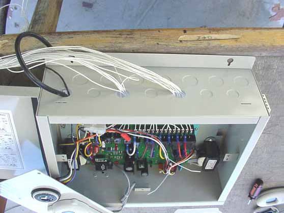
Click to zoom
Application Details
- Equipment Class
- DXT - Part 15 Low Power Transceiver, Rx Verified
- Date of Grant
- Sep 03, 2002
- Application Purpose
- Original Equipment
- Date of Application
- Sep 03, 2002
- Equipment Note
- Pool Spa / Controller -- Base Unit
- Frequency Range
- 916.50000000 - 916.50000000
- Company
- Allied Innovations, LLC
- Country
- United States
Documents & Files
Document Text
Text extracted from the exhibit documents filed with the FCC. Open a document above to read the original.
Block Diagram
ALLIED INNOVATIONS LENNOVATOR OSCILLATOR BLOCK DIAGRAM 16-AUG-02 In Base Unit and Handheld Wireless Remote Antenna 10.7 MHz Filter Transmit Crystal 14.31818 MHz 17 KHz Filter Microcontroller LNA Dual Timebase PLL Receive Crystal 14.152813 MHz SAW Filter Power Amp L Microcontroller Crystal 4.000000 MHz 10.7 MHz Filter Transmit Data Differential LO (905.78 MHz) IF Amp IF Limiter DEMOD Receive Data LVLADJ RX: 905.78 MHz TX: 916.48 MHz
Cover Letter(s)
114 OLINDA DRIVE • •• • BREA, CALIFORNIA 92823 • •• • (714) 579-0500 • •• • FAX (714) 579-1850 1 August 20, 2002 Compatible Electronics TCB 114 Olinda Drive Brea, CA 92823 Subject: Request for Certification of the Allied Innovations, LLC Pool / Spa Controller – Base Unit Model: Lennovator FCC ID: QLSLNVTRBAS102 Gentlemen: We have enclosed a package for the certification of the Allied Innovations Pool / Spa Controller – Base Unit Model: Lennovator. We have enclosed the completed Form 731 with the applicable exhibits. If you have any questions or need any additional information, please give me a call at (714) 579-0500. Sincerely, Kyle Fujimoto Test Engineer
ID Label/Location Info
Allied Innovations, LLC 15-Aug-02 PAGE 1 of 2 LENNOVATOR POOL/SPA CONTROLER LOCATION AND DIMENSIONS OF FCC ID LABELS Figure 1. Lennovator Base unit
Operational Description
Allied Innovations, LLC 20-May-02 PAGE 1 of 1 GENERAL LENNOVATOR SYSTEM OPERATION The Lennovator product is a system designed to control all the equipment in a single pool/spa combination. Its enclosure is designed for all weather outdoor use. Power to the Lennovator unit, as well as connection to the external pool and spa equipment is made by running wires through conduit and connecting them to terminal blocks inside the enclosure. All of the control and switching components (including the microprocessor and relays) are mounted on printed circuit boards also inside the enclosure. The system can be configured to operate from a 120VAC source or a two-phase 240VAC source. The functions of the Lennovator are controlled by both a handheld wireless remote control, and by the hard-wired deckside remote control. The Lennovator system is designed to control an external heater that has its own hi limit function, but the normal thermostat function is controlled by the Lennovator’s microprocessor. The jets, light, and several auxiliary functions, all of which are on timers, may be turned on and off by pressing buttons on either remote control. Controlling the operation of the pool and the spa, and setting/changing the temperature of the spa can be accomplished with the remotes. The current temperatures of the pool and spa, as well as the status of all the functions can be view on both remote controls. A regular and automatic filtration cycle can be established inside the base units’ panel, and cannot be accidentally altered by either remote control. This product is capable of automatically operating the electronic valves in a typical pool/spa combination system. The wireless remote control operates over an omnidirectional radio-frequency link and has an eight-position dipswitch that accommodates the selection of a unique address so that crosstalk between nearby units is eliminated. The operation of the deckside control is identical to the wireless remote control. However, the connection to the base unit is made with an insulated wire.
Schematics
5 5 4 4 3 3 2 2 1 1 DD CC BB AA 0.1" HEADER 0.1" HEADER USE APPROPRIATE SMD CAPACITORS AND RESISTORS *DO NOT INSTALL (3.05" WIRE) + STRAIGHT MALE STRAIGHT MALE{Doc}C PWBA, TRANSCEIVER, 916.48MHz A 11Wednesday, August 14, 2002 Title SizeDocument NumberRev Date:Sheetof DATA TO TRANSMIT TX/RX' SELECT RECEIVED DATA +5V +5V +5V +5V ANT1 ANTENNA J1 1 2 3 4 5 J2 1 2 3 4 R1 10K U2 LINX P/N: TR-916-SC-S 14 12 2 10 1 9 8 7 6 3 4 11 5 13151617181920 LVLADJ ANT RXDATA Vin GND TXDATA TXEN RXEN NC AUDIO RSSI GND PDN GNDGNDGNDGNDGNDGNDGND C3* Q1 MMBT3904DICT R3 910 Ohm C1 33 uF/10V C2 0.1 uF R2 10K A A B B C C D D E E 44 33 22 11 TIME CLOCK POWER TIME CLOCK SWITCH LO PUMP HI PUMP AUX 1 AUX 2 AUX 3 LIGHTS OZINATOR POOL SPA OPT. SPA POOL VALVE XCVR +5V DATA OUT DATA IN GND PRI PRI SEC SEC CT /RX PWR EN NOTES: Title MAIN, LENNOVATOR BASE 450192 JUMPER JP2 IS PIN 13 TO PIN 14 OF UNUSED U9 FOR THE LENNOVATOR THIS PCB HAS ADDITIONAL CIRCUITRY (NOT SHOWN HERE) THAT IS POPULATED WHEN USED IN THE ASTRO PRODUCT. SOME OF THE CIRCUITRY SHOWN HERE MAY BE REMOVED WHEN USED IN THE ASTRO. SEE THE ASTRO SCHEMATIC/BOM. 1. 2. THIS SCHEMATIC CORRESPONDS TO PCB REV. 5. 3. CHANGE HISTORY: 08-Apr-02 Rev. F Ran /RX PWR EN to uP, not GND, see section B2-3 14-Jan-02 Rev. 5 Added R36, 200 Ohm/1W, see section A4 26-Apr-02 Rev. G Change R36 from 1W to 2W. See section A4 11 G Friday, April 26, 2002 SizeDocument NumberRev Date:Sheetof LINE NEUT +24VA +12VVCC +24VA +24VA +24VA +24VA +24VB +24VB +24VB +24VB +24VB VCC VCCVCCVCCVCCVCC +24VB 12VAC-N VCC VCC VCC VCC VCC +12V RV1 250 vac J1 Line 1 J2 NEUTRAL 1 + C5 4700uF 35V + C1 2200 uF 63V C6 .1uF C8 .1uF C2 .1uF R2 2.2K R3 2.2K R4 2.2K R8 2.2K R11 2.2K R34 2.2K R27 1.1K S1 DIPSW-8 1 2 3 4 5 6 7 8 16 15 14 13 12 11 10 9 R32 2.2K J6 REMOTE HEAD 1 2 3 4 R9 100K R10 100K U10 93L46B 1 2 3 4 8 5 CS CLK DI DO VCC GND R5 680 C13 1.0 uF J5 THERMISTORS 1 2 3 4 F2 FUSE JK1 1 JK3 1 JK2 1 JK4 1 C9 1 uF C3 .1uF C10 0.1 uF U6C 74AC00 9 10 8 U6A 74AC00 1 2 3 U6B 74AC00 4 5 6 JA1 1 JA2 1 JA3 1 JB1 1 JB2 1 JB3 1 JC2 1 JC3 1 JC1 1 JD1 1 JD2 1 JD3 1 JE1 1 JE2 1 JE3 1 JF1 1 JF2 1 JG2 1 JG3 1 JG1 1 JH2 1 JH1 1 RP1 4.7K 116 215 314 413 512 6 7 8 11 10 9 R13 10K R14 10K C17 33 pF C16 33 pF Y1 4.0 MHz C12 0.1 uF C18 0.1 uF U7 16C73 2 3 4 5 6 7 21 22 23 24 25 26 27 28 11 12 13 14 15 16 17 18 9 10 1 8 19 20 RA0/AN0 RA1/AN1 RA2/AN2 RA3/AN3/Vref RA4/TOCKI RA5/AN4/SS RB0/INT RB1 RB2 RB3 RB4 RB5 RB6 RB7 RC0/T1OSO/T1CKI RC1/T1OSI/CCP2 RC2/CCP1 RC3/SCK/SCL RC4/SDI/SDA RC5/SD0 RC6/TX/CK RC7/RX/DT OSC1/CLKIN OSC2/CLKOUT MCLR/Vpp GND GND VCC R17 8.2K C14 0.1 uF C21 0.1 uF C4 0.1 uF U4 LM7812 1 2 3 VIN GND VOUT U2 LM7824 1 2 3 VIN GND VOUT J9 RJ11 CONNECTOR 1 2 3 4 J7 HEAT ENABLE J8 PUMP ENABLE C26 .1uF U5 LM7805 1 2 3 VIN GND VOUT + C7 470uF 25V U1 LM7824 1 2 3 VIN GND VOUT U3 74HC574 2 3 4 5 6 7 8 9 11 1 19 18 17 16 15 14 13 12 D1 D2 D3 D4 D5 D6 D7 D8 CLK OC Q1 Q2 Q3 Q4 Q5 Q6 Q7 Q8 R21 2.2K U6D 74AC00 12 13 11 TB1-1 . 1 . TB1-2 . 2 . TB1-3 . 3 . TB1-5 . 5 . TB1-4 . 4 . TB1-6 . 6 . TB1-7 . 7 . TB1-8 . 8 . TB1-9 . 9 . TB1-10 . 10 . TB1-11 . 11 . TB1-12 . 12 . TB1-13 . 13 . TB1-14 . 14 . TB2-1 . 1 . TB2-2 . 2 . TB2-3 . 3 . TB2-4 . 4 . TB2-5 . 5 . TB2-6 . 6 . TB2-7 . 7 . TB2-8 . 8 . K1 T-90 K2 T-90 K3 T-90 K4 T-90 K5 T-90 Q1 2N2222 Q2 2N2222 Q3 2N2222 Q4 2N2222 Q5 2N2222 Q6 2N2222 Q7 2N2222 Q8 2N2222 Q10 2N2222 K6 24V SPDT K7 24V SPDT K12 24V SPDT K9 24V SPDT K11 24V SPDT D2 1N4004 D3 1N4004 D4 1N4004 D5 1N4004 D7 1N4004 D8 1N4004 D9 1N4004 D10 1N4004 D12 1N4004 D6 LM4040 -+ D1 2 AMP R12 5 K U11 78L05 1 2367 8 Vout GndGndGndGnd Vin J4TRANSCEIVER 1 2 3 4 5 R35 1.1K J10 PRESSURE INTLK12 J3 XFRMR 1 2 3 J11 XFRMR 1 J12 XFRMR 1 J13 TRANSCEIVER 1 2 3 4 JP2 JUMPER JP1 1 R36 200 Ohm/2W 5 5 4 4 3 3 2 2 1 1 DD CC BB AA TX DATA (DATA IN) RX DATA (DATA OUT) BYPASS CAPS FOR U1 NOTE: VR1 was a 5K POT. It is now a "0" OHM resistor. 450194 Friday, March 02, 2001 3.0 SERVICE PANEL/SPA SIDE, LENNOVATOR 11 Title SizeDocument NumberRev Date:Sheetof S6 S26 S6 S5 S2 S21 S16 S11 S18 S1 S17 S12 S17 S24 S18 S8 S21 S20 S9 S16 S13 S11 S3 S13 S14 S20 S22 S0 S5 S4 S26 S22 S19 S25 S23 S14 S8 S9 S10S10 S24 S12 S23 S25 S0 S1 S2 S3 S4 S19 VCC VCC VCC C2 30 pF C3 30 pF SWX1 Custom keyboard 1 2 3 4 5 6 7 8 9 10 11 12 STATUS COM STATUS DOWN UP AUX3 AUX2 AUX1 LIGHTS JETS HEAT COM COM Y1 4.0 MHz X1 Custom LCD 2 1 3 4 5 6 7 8 9 10 11 12 13 14 15 16 17 18 19 20 21 22 23 24 25 26 27 28 29 30 31 32 BP BP NC NC NC AUX2 LIGHT HEATING 1BC 2A 2F 2G 2E 2D 2C 2B 3A 3F 3G 3E 3D JETS AUX1 AUX3 3C 3B DEG F C READY BP BP U1 16C923 63 26 29 5 19 27 20 5317 28 18 13 30 14 24 6 25 15 44 16 8 37 31 9 12 54 11 45 4 38 55 3 3968 46 67 56 65 32 66 57 47 40 48 58 49 61 50 59 51 41 62 52 33 42 43 34 36 35 60 10 2 642221 723 COM0 RC0/T1OSO/T1CKI VLCD1 RA0 VLCD2 RC1/T1OSI VLCD3 RG0/SEG20C1 RC2/CCP1 C2 RB0/INT VLCDADJ RC3/SCK/SCL OSC1/CLKIN RA1 OSC2/CLKOUT RC4/SDI/SDA RF0/SEG12 RC5/SDO RA2 RE0/SEG05 RD0/SEG00 RA3 RB1 RG1/SEG21 RA5/SS RF1/SEG13 RB2 RE1/SEG06 RG2/SEG22 RB3 RE2/SEG07RB4 RF2/SEG14 RB5 RG3/SEG23 RB6 RD1/SEG01 RB7 RG4/SEG24 RF3/SEG15 RE3/SEG08 RF4/SEG16 RG5/SEG25 RF5/SEG17 RD6/SEG30/COM2 RF6/SEG18 RG6/SEG26 RF7/SEG19 RE4/SEG09 RD7/SEG31/COM1 RG7/SEG28 RD2/SEG02 RE5/SEG10 RE6/SEG11 RD3/SEG03 RE7/SEG27 RD4/SEG04 RD5/SEG29/COM3 RA4/T0CKI MCLR/VPP VCCVCCVCC GNDGND J3 RF SIGNAL CONNEC 1 2 3 4 D3 D2 R4 10 K R10 100 Q3 2N3906 R7 10K R8 56K R5 10K R2 180 D1 LED C4 0.1uF +C1 10uF Q2 MMBT3904 R12 8.2K VR1 "0" OHM
Test Report
Report Number: B20807D1 FCC Part 15 Subpart B and FCC Section 15.249 Test Report Pool / Spa Controller – Base Unit Model: Lennovator 114 OLINDA DRIVE, BREA, CALIFORNIA 92823 PHONE: (714) 579-0500 FAX: (714) 579-1850 Page 1 of 16 FCC PART 15, SUBPART B and C TEST REPORT for POOL / SPA CONTROLLER - BASE UNIT MODEL: LENNOVATOR Prepared for ALLIED INNOVATIONS, LLC 7215 BERMUDA ROAD LAS VEGAS, NEVADA 89119-4303 Prepared by:_____________________ KYLE FUJIMOTO Approved by:____________________ MICHAEL CHRISTENSEN COMPATIBLE ELECTRONICS INC. 114 OLINDA DRIVE BREA, CALIFORNIA 92823 (714) 579-0500 DATE: AUGUST 08, 2002 REPORT APPENDICES TOTAL BODY A B C D E PAGES 16 2 2 2 13 21 56 This report shall not be reproduced except in full, without the written approval of Compatible Electronics. Report Number: B20807D1 FCC Part 15 Subpart B and FCC Section 15.249 Test Report Pool / Spa Controller – Base Unit Model: Lennovator 114 OLINDA DRIVE, BREA, CALIFORNIA 92823 PHONE: (714) 579-0500 FAX: (714) 579-1850 Page 2 of 16 TABLE OF CONTENTS Section / Title PAGE GENERAL REPORT SUMMARY 4 SUMMARY OF TEST RESULTS 4 1. PURPOSE 5 2. ADMINISTRATIVE DATA 6 2.1 Location of Testing 6 2.2 Traceability Statement 6 2.3 Cognizant Personnel 6 2.4 Date Test Sample was Received 6 2.5 Disposition of the Test Sample 6 2.6 Abbreviations and Acronyms 6 3. APPLICABLE DOCUMENTS 7 4. Description of Test Configuration 8 4.1 Description of Test Configuration - EMI 8 4.1.1 Cable Construction and Termination 9 5. LISTS OF EUT, ACCESSORIES AND TEST EQUIPMENT 10 5.1 EUT and Accessory List 10 5.2 EMI Test Equipment 11 6. TEST SITE DESCRIPTION 12 6.1 Test Facility Description 12 6.2 EUT Mounting, Bonding and Grounding 12 7. Test Procedures 13 7.1 Conducted Emissions Test 13 7.2 Radiated Emissions (Spurious and Harmonics) Test 14 8. CONCLUSIONS 16 Report Number: B20807D1 FCC Part 15 Subpart B and FCC Section 15.249 Test Report Pool / Spa Controller – Base Unit Model: Lennovator 114 OLINDA DRIVE, BREA, CALIFORNIA 92823 PHONE: (714) 579-0500 FAX: (714) 579-1850 Page 3 of 16 LIST OF APPENDICES APPENDIX TITLE A Modifications to the EUT B Additional Models Covered Under This Report C Diagrams, Charts and Photos • Test Setup Diagrams • Radiated Emissions Photos • Antenna and Effective Gain Factors D Data Sheets E Laboratory Recognitions LIST OF FIGURES FIGURE TITLE 1 Conducted Emissions Test Setup 2 Plot Map And Layout of Test Site Report Number: B20807D1 FCC Part 15 Subpart B and FCC Section 15.249 Test Report Pool / Spa Controller – Base Unit Model: Lennovator 114 OLINDA DRIVE, BREA, CALIFORNIA 92823 PHONE: (714) 579-0500 FAX: (714) 579-1850 Page 4 of 16 GENERAL REPORT SUMMARY This electromagnetic emission test report is generated by Compatible Electronics Inc., which is an independent testing and consulting firm. The test report is based on testing performed by Compatible Electronics personnel according to the measurement procedures described in the test specifications given below and in the "Test Procedures" section of this report. The measurement data and conclusions appearing herein relate only to the sample tested and this report may not be reproduced without the written permission of Compatible Electronics, unless done so in full. This report must not be used to claim product endorsement by NVLAP or any other agency of the U.S. Government. Device Tested: Pool / Spa Controller - Base Unit Model: Lennovator S/N: N/A Product Description: See Expository Statement. Modifications: The EUT was not modified during the testing. Manufacturer: Allied Innovations, LLC 7215 Bermuda Road Las Vegas, Nevada 89119-4304 Test Dates: August 6 and 7, 2002 Test Specifications : EMI requirements CFR Title 47, Part 15 Subpart B; and Subpart C, Sections 15.205, 15.207, 15.209, and 15.249 Test Procedure: ANSI C63.4: 1992 Test Deviations: The test procedure was not deviated from during the testing. SUMMARY OF TEST RESULTS TEST DESCRIPTION RESULTS 1 Conducted RF Emissions, 450 kHz - 30 MHz Complies with the Class B limits of CFR Title 47, Part 15, Subpart B; and Subpart C, section 15.207 2 Radiated RF Emissions, 10 kHz - 4300 MHz Complies with the Class B limits of CFR Title 47, Part 15, Subpart B; and Subpart C, sections 15.205, 15.209, and 15.249 Report Number: B20807D1 FCC Part 15 Subpart B and FCC Section 15.249 Test Report Pool / Spa Controller – Base Unit Model: Lennovator 114 OLINDA DRIVE, BREA, CALIFORNIA 92823 PHONE: (714) 579-0500 FAX: (714) 579-1850 Page 5 of 16 1. PURPOSE This document is a qualification test report based on the Electromagnetic Interference (EMI) tests performed on the Pool / Spa Controller - Base Unit Model: Lennovator. The EMI measurements were performed according to the measurement procedure described in ANSI C63.4: 1992. The tests were performed in order to determine whether the electromagnetic emissions from the equipment under test, referred to as EUT hereafter, are within the Class B specification limits defined by CFR Title 47, Part 15, Subpart B; and Subpart C, sections 15.205, 15.207, 15.209, and 15.249. Note: For Conducted Emissions, the limits are based on the new amended FCC rules mandated by FCC document 02-157. Report Number: B20807D1 FCC Part 15 Subpart B and FCC Section 15.249 Test Report Pool / Spa Controller – Base Unit Model: Lennovator 114 OLINDA DRIVE, BREA, CALIFORNIA 92823 PHONE: (714) 579-0500 FAX: (714) 579-1850 Page 6 of 16 2. ADMINISTRATIVE DATA 2.1 Location of Testing The EMI tests described herein were performed at the test facility of Compatible Electronics, 114 Olinda Drive, Brea, California 92823. 2.2 Traceability Statement The calibration certificates of all test equipment used during the test are on file at the location of the test. The calibration is traceable to the National Institute of Standards and Technology (NIST) . 2.3 Cognizant Personnel Allied Innovations, LLC Brooks Bishofberger Engineer Compatible Electronics, Inc. Kyle Fujimoto Test Engineer Michael Christensen Test Engineer 2.4 Date Test Sam…
Text truncated - open the document above for the full version.
Test Report
HOW THE EUT MEETS THE REQUIREMENTS OF 15.31 (e) The fundamental was maximized on the Lab D test site using a normal test setup with the EUT’s AC Adapter connected directly to the AC public mains (115 Vac). Next, the EUT’s AC Adapter was then connected to the Staco Energy Products Variable Auto Transformer Model: 3PN1010. The Variable Auto Transformer allows the Vac input to be varied. The EUT’s AC Adapter was then connected to the Staco Energy Products Variable Auto Transformer Model: 3PN1010. The AC input was then dropped to 85% (97.75 Vac) and raised to 115% (132.25 Vac). The actual AC input was measured using a calibrated Fluke Multimeter Model: 87, Serial Number: 51350019, Calibration Due Date: July 11, 2003. The fundamental was then verified again to see that the amplitude did not change. Test Result: The EUT does NOT change amplitude at the fundamental when the AC input voltage is varied between 85% and 115% of the input nominal rated supply voltage.
Contact Information
Applicant
Brooks Bishofberger(Engineer)
Technical Contact
Compatible ElectronicsKyle Fujimoto
[email protected]714-579-0500
114 Olinda Drive · Brea, California · United States
Test Firm
Compatible ElectronicsScott McCutchan
714-579-0500Fax: 714-579-1850
Technical Specifications
| # | Rule Parts | Frequency Range | Power Output |
|---|---|---|---|
| 1 | 15C | 916.5 MHz - 916.5 MHz | - |
Other Applications from Allied Innovations, LLC
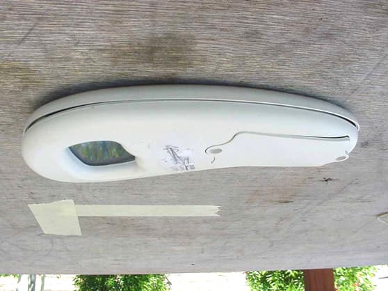
QLSLNVTRHHR102
Sep 03, 2002Pool Spa / Controller -- Hand Held Remote
Equipment Class
DXT - Part 15 Low Power Transceiver, Rx Verified