QMCM2913Universal Data Transceiver
Beckwith Electric Co., Inc.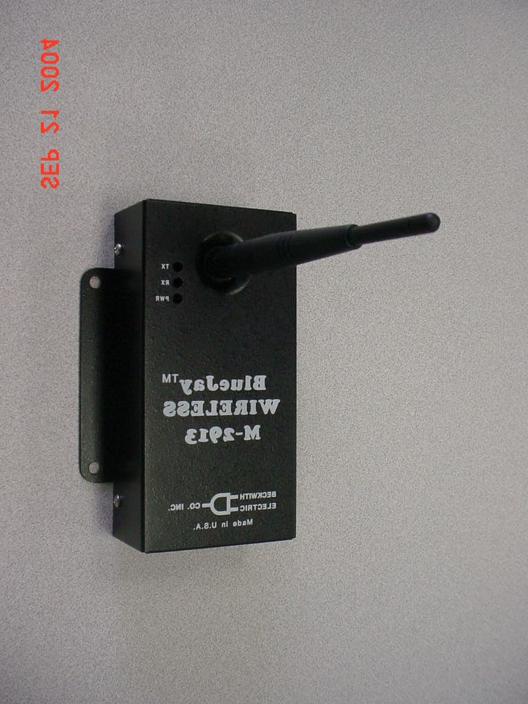
Click to zoom
Application Details
- Equipment Class
- DTS - Digital Transmission System
- Date of Grant
- Sep 21, 2004
- Application Purpose
- Original Equipment
- Date of Application
- Sep 21, 2004
- Equipment Note
- Universal Data Transceiver
- Frequency Range
- 2400.00000000 - 2483.50000000
- Company
- Beckwith Electric Co., Inc.
- Country
- United States
Documents & Files
Document Text
Text extracted from the exhibit documents filed with the FCC. Open a document above to read the original.
Users Manual
BlueJay ™ Wireless Data Transceiver M-2913 CONTROLS •Provides direct sequence spread spectrum peer-to-peer, point-to- point, point-to-multipoint and master/slave high speed (1 Mbps) data transmission rates at ranges up to 1500 feet •Interfaces with host computer running Windows 98–SE or later •Substation hardened to withstand temperatures from -40 to +80 degrees C and humidity up to 95% M-2913 BlueJay Wireless Data Transceiver –2– WARNING This equipment has been tested and found to comply with the limit requirements, pursuant to Part 15.247 of the FCC Rules. These limits are designed to provide reasonable protection against harmful interference when the equipment is operated in a commercial environment. This equipment generates, uses, and can radiate radio frequency energy, and, if not installed and used in accordance with the instruction manual, may cause harmful interference to radio communications. Operation of this equipment in a residential area is likely to cause harmful interference in which case the user will be required to correct the interference at his own expense. Only the antenna provided is authorized for use with the M-2913. If the antenna is lost or damaged, please contact Beckwith Electric Co., Inc. to secure a replacement antenna. This product generates, uses, and can radiate radio frequency (RF). If it is not installed and used in accordance with the operating instructions, it can cause harmful interference to communications. If this equipment causes harmful interference to radio or television reception, the user should try and correct the interference by: • Reorienting or relocating the receiving/transmitting antenna • Increasing the separation between the equipment and the M-2913 • Connecting the equipment into an outlet on a different circuit from the M-2913. If these do not correct the interference, consult an experienced radio/television technician for assistance. Correcting such interference is the responsibility of the user, not the manufacturer. Changes or modifications not expressly approved by Beckwith Electric Co., Inc. may void the user's authority to operate the equipment. FCC Radiation Exposure Statement This equipment complies with FCC radiation exposure limits set forth for uncontrolled equipment. This equipment should be installed and operated with a minimum distance of at least 20 cm between the radiator and person's body (excluding extremities) and must not be located or operated with any other antenna or transmitter. –3– M-2913 BlueJay Wireless Data Transceiver The M-2913 BlueJay ™ Wireless Data Transceiver is a self-contained short-range wireless communication device (SRD) that is used for transferring data between a host computer and Intelligent Electrical Device using the Universal Serial Bus (USB). The M-2913 is based on an Intersil direct sequence spread spectrum chip set that operates in the 2.4 GHz ISM band. The M-2913 design meets the category for low power devices (LPDs) standard requirement for license-free operation. Interface The M-2913 uses the standard USB B-connector to connect to the host computer. The transmission rate of the USB using the interrupt endpoint is TBD Mbps. Data Transmission: • Error Detection – 16 bit CRC • Maximum throughput – 500 Kbps Communication The M-2913 conditions the data and transmits it over a half-duplex direct sequence spread spectrum radio operating in the 2.4 GHz ISM band. The over-the-air data rate is TBD Mbps. Transmit: • 1 Mbps Receive: • 1 Mbps The M-2913 BlueJay Wireless Data Transceiver is used with a laptop or desktop computer, and if it is to be used within a metal-enclosed structure, a cable extension must be used and the antenna mounted externally. Antennas must be oriented in the same plane and located in view of the corresponding transceiver. Beckwith Electric cable extensions are available in 18", 6' and 13' lengths (See Accessories). ■NOTE: For maximum range, all antennas must be oriented in the same plane. Accessories 18" Cable Extension – Beckwith Electric Part No. 420-00395 6' Cable Extension – Beckwith Electric Part No. 420-00391 13' Cable Extension – Beckwith Electric Part No. 420-00392 M-TBD – TBD' USB Extension Cable Power The M-2913 gets its power from the host computer. When the M-2913 is plugged into the USB A-type connector resident on the host, power is provided. The maximum current used by the M-2913 is 500 mA. Configuration The address will be set by the user application. The M-2913 must be run under Windows™ 98-SE version, or later. M-2913 BlueJay Wireless Data Transceiver –4– Typical Connections Guide The M-2913 can be applied in one of two methods. 1.Point-to-Point Configuration: Between an M-2913 and an M-2911, with the M-2913 connected to a host computer running Windows™ 98-SE or later, and the M-2911 connected to a PC, modem, or another IED. Detailed elements of a typical Point-to-Point configuration are as follows: a. One M-2913 is connected to a PC USB port using a typical USB cable. b. The second M-2913 is connected to the RS-232 port of a M-2667 Autodaptive ® Tapchanger Control using an RS-232 straight through cable and gender changer. Communications can now be established between the PC and M-2667 as if they were directly connected. In this example, if the SLIMcom Communications Software were to be used, the software should detect that the M-2913 is connected to the PC, and then prompt the user for an address. 2.Point-to-Multipoint Configuration (also known as Master/Slave): In the Point-to-Multipoint configuration, one M-2913 is configured as the Master unit with multiple-connected IED units configured as Slaves (see AT Commands in the M-2911 Specifications for Master/Slave setup). This configuration may be used where, for example, the Master unit is located in a control house and the slaves are spread out throughout a substation yard. Detailed elements of a typical Point to Multipoint configuration are as follows: a. One M-2913 (Master) is connected to the USB po…
Text truncated - open the document above for the full version.
Cover Letter(s)
FCC ID: QMCM2913 Request for Confidentiality In accordance with 47 C.F.R. Section 0.459, we, Beckwith Electric Company, Inc., hereby request confidentiality for the model M-2913 block diagram, schematic and product description presented for certification. In support of the Request for Confidentiality, the following is stated: Enclosed within this application is technical information which we deem to be trade secrets and proprietary. If made public, the information might be used to our disadvantage. To assist in assuring that we receive the full value of our product and protect its competitive posture, we respectfully request this grant of confidentiality. M.Mosele Beckwith Electric Company, Inc.
Test Report
Page 1 of 44 TABLE OF CONTENTS Engineering Test Report No. 33926-01 Measurement of RF Interference from a Model M-2913 Blue Jay Wireless Data Transceiver Using Digital Modulation For : Beckwith Electric Largo, FL P.O. No. : 35097 Date Received : August 6, 2004 Date Tested : August 16, 2004 through September 7, 2004 Test Personnel : Mark E. Longinotti, NARTE® Certified EMC Test Engineer, ATL-0154-E Specification : FCC "Code of Federal Regulations" Title 47 Part 15, Subpart C, Section 15.247 for Intentional Radiators Using Digital Modulation Operating within the 2400- 2483.5MHz band. Test Report By : Mark E. Longinotti NARTE® Certified EMC Test Engineer, ATL-0154-E Approved By : Raymond J. Klouda Registered Professional Engineer of Illinois - 44894 Elite Electronic Engineering Inc. 1516 Centre Circle Downers Grove, IL 60515 Tel : (630) 495-9770 Fax: (630) 495-9785 www.elitetest.com Engineering Test Report No. 33926-01 THIS REPORT SHALL NOT BE REPRODUCED, EXCEPT IN FULL, WITHOUT THE WRITTEN APPROVAL OF ELITE ELECTRONIC ENGINEERING INCORPORATED. Page 2 of 44 PARAGRAPH DESCRIPTION OF CONTENTS PAGE NO. 1.0 INTRODUCTION.......................................................................................................................................................................................3 1.1 Description of Test Item......................................................................................................................................................................3 1.2 Purpose...................................................................................................................................................................................................3 1.3 Deviations, Additions and Exclusions..............................................................................................................................................3 1.4 Applicable Documents.........................................................................................................................................................................3 1.5 Subcontractor Identification...............................................................................................................................................................3 1.6 Laboratory Conditions.........................................................................................................................................................................3 2.0 TEST ITEM SETUP AND OPERATION.................................................................................................................................................4 2.1 Power Input............................................................................................................................................................................................4 2.2 Grounding..............................................................................................................................................................................................4 2.3 Peripheral Equipment............................................................................................................................................................................4 2.4 Interconnect Cables..............................................................................................................................................................................4 2.5 Operational Mode.................................................................................................................................................................................4 3.0 TEST EQUIPMENT....................................................................................................................................................................................4 3.1 Test Equipment List..............................................................................................................................................................................4 3.2 Calibration Traceability........................................................................................................................................................................4 4.0 REQUIREMENTS, PROCEDURES AND RESULTS..............................................................................................................................4 4.1 Powerline Conducted Emissions........................................................................................................................................................4 4.1.1 Requirements.................................................................................................................................................................................4 4.1.2 Procedures.....................................................................................................................................................................................5 4.1.3 Results............................................................................................................................................................................................5 4.2 Antenna Conducted Emissions..........................................................................................................................................................5 4.2.1 Requirements.................................................................................................................................................................................5 4.2.2 Procedures.....................................................................................................................................................................................6 4.2.3 Results....................................................................................................................................................................................…
Text truncated - open the document above for the full version.
Contact Information
Applicant
Mike Mosele(Compliance Test Engineer)
Test Firm
Elite Electronic Engineering Co.Daniel Crowder
Technical Specifications
| # | Rule Parts | Frequency Range | Power Output |
|---|---|---|---|
| 1 | 15C | 2.40 GHz - 2.48 GHz | 177.00 mW |
Other Applications from Beckwith Electric Co., Inc.
QMCM2910
Aug 14, 2003Universal Data Transceiver
Equipment Class
DTS - Digital Transmission System
QMCM2911
Nov 10, 2002DSS Universal Data Transceiver
Equipment Class
DSS - Part 15 Spread Spectrum Transmitter