QOQ-MGM240LRadio Module with BLE and 802.15.4
Silicon Laboratories Finland Oy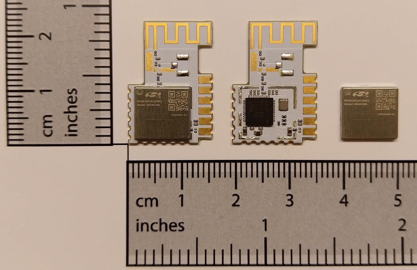
Click to zoom
Application Details
- Equipment Class
- DTS - Digital Transmission System
- Date of Grant
- Aug 20, 2022
- Application Purpose
- Original Equipment
- Date of Application
- Jul 24, 2022
- Equipment Note
- Radio Module with BLE and 802.15.4
- Frequency Range
- 2405.00000000 - 2480.00000000
- Country
- Finland
Documents & Files
Document Text
Text extracted from the exhibit documents filed with the FCC. Open a document above to read the original.
Users Manual
MGM240L Wireless Gecko Multi-Protocol Lighting Module Data Sheet The MGM240L is a module designed and built to meet the performance, security, and reliability requirements of line-powered, smart LED lighting products. Based on the EFR32MG24 SoC, it includes a Bluetooth ® Low Energy 5.3 implementation, and 802.15.4-based full stacks to enable applications using industry-standard wireless proto- cols such as Zigbee ® and Thread ® , for multiprotocol connectivity and for Matter-ready Smart Home connectivity, delivering best-in-class RF performance, CA Title 20 energy consumption compliance, future-proof capability for feature and OTA firmware updates, enhanced security, and a form factor and temperature rating suited for enclosed opera- tion in lightbulb housings. The MGM240L is a complete solution that comes with fully-upgradeable, robust soft- ware stacks, world-wide regulatory certifications, advanced development and debugging tools, and support that will simplify and minimize the development cycle and deployment of your product helping to accelerate its time-to-market. The MGM240L is targeted for key applications that include: • Smart LED lightbulbs • Connected lighting KEY FEATURES • Bluetooth 5.3 and 802.15.4 radio-equipped module • PCB Trace antenna • 10 dBm max TX power • TBD dBm 802.15.4 RX sensitivity • TBD dBm Bluetooth RX sensitivity @ 1 Mbps • 32-bit ARM® Cortex®-M33 core with 78.0 MHz maximum operating frequency • Up to 1536 kB of flash and 256 kB of RAM • Enhanced security features • Optimal set of MCU peripherals • 12 GPIO pins • -40 to 125°C • 15.5 mm x 22.5 mm (custom form factor) silabs.com | Building a more connected world.Copyright © 2022 by Silicon LaboratoriesPreliminary Rev. 0.5 This information applies to a product under development. Its characteristics and specifications are subject to change without notice. 1. Features •Supported Protocols • 802.15.4 • • Zigbee • Open Thread • Proprietary • Bluetooth Low Energy (BLE) 5.3 • Bluetooth Mesh • Matter-ready Smart Home Connectivity • Multi-protocol •Wireless System-on-Chip • High Performance 32-bit 78.0 MHz ARM Cortex ® -M33 with the following: • DSP instruction and floating-point unit for efficient signal processing • Up to 1536 kB flash program memory • Up to 256 kB RAM data memory • 2.4 GHz radio operation •Receiver Performance • -105.8 dBm sensitivity (1% PER) at 250 kbps O-QPSK DSSS • -106.2 dBm sensitivity (0.1% BER) at 125 kbps GFSK • -101.9 dBm sensitivity (0.1% BER) at 500 kbps GFSK • -98.2 dBm sensitivity (0.1% BER) at 1 Mbps GFSK • -95.4 dBm sensitivity (0.1% BER) at 2 Mbps GFSK •Current Consumption • 7.7 mA RX current at 250 kbps O-QPSK DSSS • 6.6 mA RX current at 1 Mbps GFSK • 7.4 mA TX current at 0 dBm • 29.8 mA TX current at 10 dBm • 47.1 μA/MHz in Active Mode (EM0) at 39.0 MHz • 1.9 μA EM2 DeepSleep current (16 kB RAM retention and RTC running from LFRCO) •Regulatory Certifications • EU (CE) • UK (UKCA) • USA (FCC) • Canada (ISED) • Australia (ACMA) • Dominican Republic (INDOTEL) • Hong Kong (OFCA) • Serbia (RATEL) • Israel (MOC) • Jordan (TRC) • Kuwait (CITRA) • Morocco (ANRT) • Qatar (CRA) • Singapore (IMDA) • Bahrain (BTRA) • Egypt (NTRA) • Japan (MIC) • South Korea (KC) • China (SRRC) • Regulatory Certifications (cont.) • Taiwan (NCC) • Mexico (IFT) • Thailand (NBTC) • Oman (OTRA) • Saudi Arabia (CITC) • United Arab Emirates (TRA) •Operating Range • 1.8 to 3.8 V • -40 to +125°C •Dimensions • 15.5 mm x 22.5 mm (custom form factor) •Secure Vault • Hardware Cryptographic Acceleration for AES128/192/256, ChaCha20-Poly1305, SHA-1, SHA-2/256/384/512, ECDSA +ECDH(P-192, P-256, P-384, P-521), Ed25519 and Curve25519, J-PAKE, PBKDF2 • True Random Number Generator (TRNG) • ARM ® TrustZone ® • Secure Boot (Root of Trust Secure Loader) • Secure Debug Unlock • DPA Countermeasures • Secure Key Management with PUF • Anti-Tamper • Secure Attestation •MCU Peripherals • Analog to Digital Converter (IADC), 12-bit @ 1 Msps or 16- bit @ 76.9 ksps • 2 × Analog Comparator (ACMP) • 2 × Digital to Analog Converter (VDAC) • 12 General Purpose I/O pins with output state retention and asynchronous interrupts • 8 Channel DMA Controller (LDMA) • 16 Channel Peripheral Reflex System (PRS) • 3 × 16-bit Timer/Counter with 3 Compare/Capture/PWM channels (TIMER2/3/4) • 2 × 32-bit Timer/Counter with 3 Compare/Capture/PWM channels (TIMER0/1) • 2 × 32-bit Real Time Counter (SYSRTC/BURTC) • 24-bit Low Energy Timer for waveform generation (LETIM- ER) • 16-bit Pulse Counter with asynchronous operation (PCNT) • 2 × Watchdog Timer (WDOG) • 1 × Universal Synchronous/Asynchronous Receiver/Trans- mitter (USART), supporting UART/SPI/SmartCard (IS7816)/ IrDA/I2S • 2 × Enhanced Universal Synchronous/Asynchronous Re- ceiver/Transmitter (EUSART) supporting UART/SPI/DALI/ IrDA • 2 × I2C interface with SMBus support • Low-Frequency RC Oscillator with precision mode to re- place 32 kHz sleep crystal (LFRCO) • Die temperature sensor with +/-1.5 °C accuracy after single- point calibration MGM240L Wireless Gecko Multi-Protocol Lighting Module Data Sheet Features silabs.com | Building a more connected world.Preliminary Rev. 0.5 | 2 2. Ordering Information Table 2.1. Ordering Information Ordering CodeProtocol StackMax TX Power Freq Band AntennaFlash (kB) RAM (kB) GPIOTemp RangePackaging MGM240L022RNF2Bluetooth 5.3 and 802.15.4 10 dBm2.4 GHzInverted-F PCB Trace 153625612-40 to 125Cut Tape MGM240L022RNF2RBluetooth 5.3 and 802.15.4 10 dBm2.4 GHzInverted-F PCB Trace 153625612-40 to 125Reel The maximum RF TX power allowed by different regional regulatory authorities may differ from the maximum output power a module can produce. End-product manufacturers must then verify that the module is configured to meet the regulatory limits for each region in accordance with the local rules and the formal certification test reports. MGM240L modules are pre-programmed with UART XMODEM bootloader. The modules may be referred to by their product family name (MGM240L), model name …
Text truncated - open the document above for the full version.
Users Manual
Silicon Laboratories Finland Oy Alberga Business Park, Bertel Jungin aukio 3 FI-02600 Espoo, Finland www.silabs.com | Phone: +358 9 435 5060 Page 1 of 2 Photos of the Bluetooth Low Energy and 802.15.4 wireless radio module with model name of MGM240L Figure 1: Top/Front External and Internal View of the MGM240L Module Silicon Laboratories Finland Oy Alberga Business Park, Bertel Jungin aukio 3 FI-02600 Espoo, Finland www.silabs.com | Phone: +358 9 435 5060 Page 2 of 2 Figure 2: Bottom/Rear External View of the MGM240L Module
Attestation Statements
Equipment Description Technical Description: (Please provide a brief description of the intended use of the equipment including the technologies the product supports) Internally regulated, and shielded, PCB radio module implementing the Bluetooth Low Energy (BLE) and 802.15.4 wireless standard protocols, to enable low-power wireless communication for IoT applications. The BLE portion supports the 1M, 2M, and 125/500K coded PHYs from the spec, all based on the GFSK modulation. The 802.15.4 portion provides the base wireless protocol for higher-level communication standards like Zigbee and Thread. The product comes in a single hardware variant with an integral antenna, a meandered inverted F PCB trace. Manufacturer: Silicon Laboratories Finland Oy (address: Alberga Business Park, Bertel Jungin aukio 3, FI-02600 Espoo, Finland) Model Name: MGM240L Brand Name: Silicon Labs Hardware Version: 1.0 Software Version: 4.0.x (Gecko SDK) FCC ID of the product under test – see guidance here QOQ-MGM240L IC ID of the product under test – see guidance here 5123A-MGM240L Intentional Radiators Technology Bluetooth Low Energy 802.15.4 Frequency Range (MHz to MHz) 2402 to 2480 2405 to 2480 Conducted Declared Output Power (dBm) 10 10 Antenna Gain (dBi) 0.64 0.64 Supported Bandwidth(s) (MHz) (e.g. 1 MHz, 20 MHz, 40 MHz) 1M PHY: 1 2M PHY: 2 3.5 Modulation Scheme(s) (e.g. GFSK, QPSK etc) GFSK O-QPSK ITU Emission Designator (see guidance here) (not mandatory for Part 15 devices) Bottom Frequency (MHz) 2402 2405 Middle Frequency (MHz) 2440 2445 Top Frequency (MHz) 2480 2480 Un-intentional Radiators Highest frequency generated or used in the device or on which the device operates or tunes Lowest frequency generated or used in the device or on which the device operates or tunes Class A Digital Device (Use in commercial, industrial or business environment) ☐ Class B Digital Device (Use in residential environment only) ☐ AC Power Source AC supply frequency: Hz Voltage V Max current: A Single Phase ☐ Three Phase ☐ DC Power Source Nominal voltage: 3.0 V Extreme upper voltage: 3.8 V Extreme lower voltage: 1.8 V Max current: 30 mA Battery Power Source Voltage: V End-point voltage: V (Point at which the battery will terminate) Alkaline ☐ Leclanche ☐ Lithium ☐ Nickel Cadmium ☐ Lead Acid* ☐ *(Vehicle regulated) Other ☐ Please detail: Charging Can the EUT transmit whilst being charged Yes ☐ No ☐ Temperature Minimum temperature: -40 °C Maximum temperature: +125 °C Cable Loss Adapter Cable Loss (Conducted sample) 0.3 dB Antenna Characteristics Antenna connector ☐ State impedance Ohm Temporary antenna connector ☐ State impedance Ohm Integral antenna ☒ Type: Meandered Inverted-F PCB trace Gain 0.64 dBi External antenna ☐ Type: Gain dBi For external antenna only: Standard Antenna Jack ☐ If yes, describe how user is prohibited from changing antenna (if not professional installed): Equipment is only ever professionally installed ☐ Non-standard Antenna Jack ☐ Ancillaries (if applicable) Manufacturer: Part Number: Model: Country of Origin: I hereby declare that the information supplied is correct and complete. Name: Enrico Taddeo Position held: Senior Application and Certification Engineer Date: 25 April 2022
Cover Letter(s)
Silicon Laboratories Finland Oy Alberga Business Park, Bertel Jungin aukio 3 FI-02600 Espoo, Finland www.silabs.com | +358 9 435 5060 Cover Letter for Confidentiality Federal Communications Commission (Authorization and Evaluation Division) 7435 Oakland Mills Road, Columbia, MD 21046 Attn: To Whom it May Concern / Application Examiner / Review Engineer / Officer in Charge Re: Permanent Confidentiality Request for FCC ID: QOQ-MGM240L Dear Madam or Sir, We, Silicon Laboratories Finland Oy, a corporation branch and subsidiary of Silicon Laboratories Inc., validly organized and existing under the laws of Finland, having its principal place of business at Alberga Business Park, Bertel Jungin aukio 3, 02600 Espoo, Finland, pursuant to Sections 0.457 and 0.459 of the Commission’s Rules, hereby request the permanent confidential treatment of information as outlined below: Schematics, PCB layout, Bill of Materials, Block Diagram, Operational Description The above design material relates to the FCC application for equipment authorization in connection with our Bluetooth Low Energy and 802.15.4 wireless radio modules with model name of MGM240L, having FCC ID: QOQ-MGM240L. The above design material contains trade secrets and proprietary information not customarily released to the public. The public disclosure of these matters might be harmful to our business and provide unjustified benefits to our competitors. We understand that pursuant to Rule 0.457, disclosure of the application and all other accompanying documentation shall not be made before the date of the related Grant release. Should there be any query regarding this authorization, please do not hesitate to contact the undersigned. Thank you for your attention to this matter. Place and date of issue (of this letter): Espoo, June 17, 2022 Authorized Signatory: Enrico Taddeo Job Title: Senior Applications and Certifications Engineer eMail: [email protected]
Cover Letter(s)
Silicon Laboratories Finland Oy Alberga Business Park, Bertel Jungin aukio 3 FI-02600 Espoo, Finland www.silabs.com | +358 9 435 5060 Single-modular Transmitter Approval Request Letter Attn: To Whom it May Concern / Application Examiner / Review Engineer / Officer in Charge Re: Request for FCC modular approval, Model: MGM240L, FCC ID: QOQ- MGM240L Dear Madam or Sir, We, Silicon Laboratories Finland Oy, a corporation branch and subsidiary of Silicon Laboratories Inc., validly organized and existing under the laws of Finland, having its principal place of business at Alberga Business Park, Bertel Jungin aukio 3, 02600 Espoo, Finland, hereby request a Single-modular transmitter approval for the radio equipment referenced above. The radio transmitter device meets the requirements for obtaining a (Full-) Single-modular transmitter approval as indicated below, as outlined in the KDB 996369 D01 Module Certification Guide v02 1] The radio elements of the module have the radio frequency circuitry shielded. 2] The module has buffered modulation/data inputs to ensure that the device complies with Part 15 requirements with any type of input signal. 3] The module contains its own power supply regulation to ensure compliance with Part 15 requirements, regardless of the quality or level of external DC supply from the host unit. 4] The module has a permanently attached antenna. 5] The module has demonstrated compliance in a stand-alone configuration. 6] The module is labeled with its permanently affixed FCC ID label; additionally, the integration manual mentions the FCC ID and the need by the integrator to refer to it in the label of the end-product labelling. 7] The module does comply with any and all specific FCC rules applicable to this kind of transmitter, including the provision of all the instructions and conditions for maintaining compliance, as detailed in the integration instructions by the grantee. 8] The module does comply with any and all applicable RF exposure requirements. Should there be any query regarding this request, please do not hesitate to contact the undersigned. Thank you for your attention to this matter. Place and date of issue (of this letter): Espoo, July 12, 2022 Senior Contact: Enrico Taddeo Job Title: Senior application and certification engineer eMail: [email protected]
External Photos
Silicon Laboratories Finland Oy Alberga Business Park, Bertel Jungin aukio 3 FI-02600 Espoo, Finland www.silabs.com | Phone: +358 9 435 5060 Page 1 of 2 Photos of the Bluetooth Low Energy and 802.15.4 wireless radio module with model name of MGM240L Figure 1: Top/Front External and Internal View of the MGM240L Module Silicon Laboratories Finland Oy Alberga Business Park, Bertel Jungin aukio 3 FI-02600 Espoo, Finland www.silabs.com | Phone: +358 9 435 5060 Page 2 of 2 Figure 2: Bottom/Rear External View of the MGM240L Module
ID Label/Location Info
MGM240L METALLIC SHIELD (TOP) SILK SCREEN (BOTTOM) TOP SHIELD AND SILK SCREEN MARKINGS MGM240L METALLIC SHIELD SILK SCREEN DIMENSIONS OF MARKINGS
Internal Photos
Silicon Laboratories Finland Oy Alberga Business Park, Bertel Jungin aukio 3 FI-02600 Espoo, Finland www.silabs.com | Phone: +358 9 435 5060 Page 1 of 2 Photos of the Bluetooth Low Energy and 802.15.4 wireless radio module with model name of MGM240L Figure 1: Top/Front External and Internal View of the MGM240L Module Silicon Laboratories Finland Oy Alberga Business Park, Bertel Jungin aukio 3 FI-02600 Espoo, Finland www.silabs.com | Phone: +358 9 435 5060 Page 2 of 2 Figure 2: Bottom/Rear External View of the MGM240L Module
RF Exposure Info
TÜV SÜD, Octagon House, Concorde Way, Segensworth North, Fareham, Hampshire, United Kingdom, PO15 5RL Tel: +44 (0) 1489 558100 Website: www.tuvsud.com/en COMMERCIAL-IN-CONFIDENCE SAR EXCLUSION DOCUMENT ©2022 Not to be reproduced, except in its entirety, without the permission of TÜV SÜD Page 1 of 3 Document 75955217-09 Issue 01 FCC ID: QOQ-MGM240L 2400 MHz Bluetooth Low Energy Transmitter: FCC General RF Exposure Test Exemption Guidance (KDB 447498 D04 v01 Appendix B) SAR or MPE based evaluation is not required if any of the applicable Steps 1, 2 or 3 are met (Ref: KDB 447448 Figure A.1). Step 1: All Devices: Blanket 1 mW Exemption (100 kHz – 100 GHz) Reference: FCC CFR 47 Part 1.1307(b)(3)(i)(A). Frequency (MHz) Conducted Power Output mW Duty Cycle % Time Average Conducted Power Output mW Antenna Gain Ratio Maximum Power (EIRP) mW Maximum Power (ERP) mW Test Separation Distance (mm) All devices: 1.1307(b)(3)(i)(A)Blanket 1 mW Exemption (Yes/No)* (100 kHz to 100 GHz) 2402 10 83 8.3 1.159 9.6197 5.87 12.5 No *Based on conducted power output or ERP whichever is greater, compared to the 1 mW exemption threshold. Step 2: All devices: MPE Exemption (300 kHz to 100 GHz) Reference: FCC CFR 47 Part 1.1307(b)(3)(i)(C). Frequency (MHz) Conducted Power Output mW Duty Cycle % Time Average Conducted Power Output mW Antenna Gain Ratio Maximum Power (EIRP) mW Maximum Power (ERP) mW Test Separation Distance (mm) Threshold ERP at separation distance R (W) All devices: 1.1307(b)(3)(i)(C) MPE Exemption (Yes/No)** (300 kHz to 100 GHz) 2402 10 83 8.3 1.159 9.6197 5.87 12.5 Less than minimum separation distance No **Based on ERP compared to the KDB 447498 Table B.1 Threshold ERP calculated for the separation distance R. Approved by Date 17 June 2022 Matthew Russell Authorised Signatory TÜV SÜD, Octagon House, Concorde Way, Segensworth North, Fareham, Hampshire, United Kingdom, PO15 5RL Tel: +44 (0) 1489 558100 Website: www.tuvsud.com/en COMMERCIAL-IN-CONFIDENCE SAR EXCLUSION DOCUMENT ©2022 Not to be reproduced, except in its entirety, without the permission of TÜV SÜD Page 2 of 3 Step 3: All Devices: (if Step 1 & 2 not met): SAR Exemption (300 MHz to 6 GHz, 0.5 cm to 40 cm) Reference: FCC CFR 47 Part 1.1307(b)(3)(i)(B). Frequency (MHz) Conducted Power Output mW Duty Cycle % Time Average Conducted Power Output mW Antenna Gain Ratio Maximum Power (EIRP) mW Maximum Power (ERP) mW Test Separation Distance (mm) Threshold Pth (mW) All devices: 1.1307(b)(3)(i)(B) SAR Exemption (Yes/No)* (300 MHz to 6 GHz, 0.5 cm to 40 cm) 2402 10 83 8.3 1.159 9.6197 5.87 12.5 9.0 Yes *Based on conducted power output or ERP whichever is greater, compared to the Pth KDB 447498 B.2 formula;. The SAR and MPE exclusion thresholds have been evaluated using the formula described above from information supplied by the manufacturer below. Based on the calculations above, the product is categorically excluded from SAR or MPE evaluation at any supported power level and at any distance from the human body above 12.5 mm. ©2022 Not to be reproduced, except in its entirety, without the permission of TÜV SÜD Page 3 of 3 Document Number: 75955217-09 | Issue: 01 COMMERCIAL-IN-CONFIDENCE Manufacturer’s Declaration of Product information: Technical Description Internally regulated, and shielded, PCB radio module implementing the Bluetooth Low Energy (BLE) and 802.15.4 wireless standard protocols, to enable low-power wireless communication for IoT applications. The BLE portion supports the 1M, 2M, and 125/500K coded PHYs from the spec, all based on the GFSK modulation. The 802.15.4 portion provides the base wireless protocol for higher- level communication standards like Zigbee and Thread. The product comes in a single hardware variant with an integral antenna, a meandered inverted F PCB trace. Transmitter Description The following radio access technologies and frequency bands are supported by the equipment under test. Radio Access Technology Frequency Band (MHz) Minimum Frequency (MHz) Output Power (dBm) Duty Cycle (%) Bluetooth Low Energy 2400 -2483.5 2402 10 83 Transmitter Description Antenna Description The following antennas are supported by the equipment under test. Radio Access Technology Antenna Model Gain (dBi) Antenna length (cm) Bluetooth Low Energy Integrated PCB trace antenna +0.64 3.5 Antenna Description
RF Exposure Info
TÜV SÜD, Octagon House, Concorde Way, Segensworth North, Fareham, Hampshire, United Kingdom, PO15 5RL Tel: +44 (0) 1489 558100 Website: www.tuvsud.com/en COMMERCIAL-IN-CONFIDENCE SAR EXCLUSION DOCUMENT ©2022 Not to be reproduced, except in its entirety, without the permission of TÜV SÜD Page 1 of 3 Document 75955217-10 Issue 01 FCC ID: QOQ-MGM240L 2400 MHz 802.15.4 Transmitter: FCC General RF Exposure Test Exemption Guidance (KDB 447498 D04 v01 Appendix B) SAR or MPE based evaluation is not required if any of the applicable Steps 1, 2 or 3 are met (Ref: KDB 447448 Figure A.1). Step 1: All Devices: Blanket 1 mW Exemption (100 kHz – 100 GHz) Reference: FCC CFR 47 Part 1.1307(b)(3)(i)(A). Frequency (MHz) Conducted Power Output mW Duty Cycle % Time Average Conducted Power Output mW Antenna Gain Ratio Maximum Power (EIRP) mW Maximum Power (ERP) mW Test Separation Distance (mm) All devices: 1.1307(b)(3)(i)(A)Blanket 1 mW Exemption (Yes/No)* (100 kHz to 100 GHz) 2405 10 100 10 1.159 11.59 7.07 13.5 No *Based on conducted power output or ERP whichever is greater, compared to the 1 mW exemption threshold. Step 2: All devices: MPE Exemption (300 kHz to 100 GHz) Reference: FCC CFR 47 Part 1.1307(b)(3)(i)(C). Frequency (MHz) Conducted Power Output mW Duty Cycle % Time Average Conducted Power Output mW Antenna Gain Ratio Maximum Power (EIRP) mW Maximum Power (ERP) mW Test Separation Distance (mm) Threshold ERP at separation distance R (W) All devices: 1.1307(b)(3)(i)(C) MPE Exemption (Yes/No)** (300 kHz to 100 GHz) 2405 10 100 10 1.159 11.59 7.07 13.5 Less than minimum separation distance No **Based on ERP compared to the KDB 447498 Table B.1 Threshold ERP calculated for the separation distance R. Approved by Date 17 June 2022 Matthew Russell Authorised Signatory TÜV SÜD, Octagon House, Concorde Way, Segensworth North, Fareham, Hampshire, United Kingdom, PO15 5RL Tel: +44 (0) 1489 558100 Website: www.tuvsud.com/en COMMERCIAL-IN-CONFIDENCE SAR EXCLUSION DOCUMENT ©2022 Not to be reproduced, except in its entirety, without the permission of TÜV SÜD Page 2 of 3 Step 3: All Devices: (if Step 1 & 2 not met): SAR Exemption (300 MHz to 6 GHz, 0.5 cm to 40 cm) Reference: FCC CFR 47 Part 1.1307(b)(3)(i)(B). Frequency (MHz) Conducted Power Output mW Duty Cycle % Time Average Conducted Power Output mW Antenna Gain Ratio Maximum Power (EIRP) mW Maximum Power (ERP) mW Test Separation Distance (mm) Threshold Pth (mW) All devices: 1.1307(b)(3)(i)(B) SAR Exemption (Yes/No)* (300 MHz to 6 GHz, 0.5 cm to 40 cm) 2405 10 100 10 1.159 11.59 7.07 13.5 10.6 Yes *Based on conducted power output or ERP whichever is greater, compared to the Pth KDB 447498 B.2 formula; The SAR and MPE exclusion thresholds have been evaluated using the formula described above from information supplied by the manufacturer below. Based on the calculations above, the product is categorically excluded from SAR or MPE evaluation at any supported power level and at any distance from the human body above 13.5 mm. ©2022 Not to be reproduced, except in its entirety, without the permission of TÜV SÜD Page 3 of 3 Document Number: 75955217-10 | Issue: 01 COMMERCIAL-IN-CONFIDENCE Manufacturer’s Declaration of Product information: Technical Description Internally regulated, and shielded, PCB radio module implementing the Bluetooth Low Energy (BLE) and 802.15.4 wireless standard protocols, to enable low-power wireless communication for IoT applications. The BLE portion supports the 1M, 2M, and 125/500K coded PHYs from the spec, all based on the GFSK modulation. The 802.15.4 portion provides the base wireless protocol for higher- level communication standards like Zigbee and Thread. The product comes in a single hardware variant with an integral antenna, a meandered inverted F PCB trace. Transmitter Description The following radio access technologies and frequency bands are supported by the equipment under test. Radio Access Technology Frequency Band (MHz) Minimum Frequency (MHz) Output Power (dBm) Duty Cycle (%) 802.15.4 2400 – 2483.5 2405 10 100 Transmitter Description Antenna Description The following antennas are supported by the equipment under test. Radio Access Technology Antenna Model Gain (dBi) Antenna length (cm) 802.15.4 Integrated PCB trace antenna +0.64 3.5 Antenna Description
RF Exposure Info
TÜV SÜD is a trading name of TUV SUD Ltd Registered in Scotland at East Kilbride, Glasgow G75 0QF, United Kingdom Registered number: SC215164 TUV SUD Ltd is a TÜV SÜD Group Company Phone: +44 (0) 1489 558100 Fax: +44 (0) 1489 558101 www.tuvsud.com/en TÜV SÜD Octagon House Concorde Way Fareham Hampshire PO15 5RL United Kingdom TÜV SÜD SIGNATURE NAME JOB TITLE RESPONSIBLE FOR ISSUE DATE Matthew Russell Senior Engineer (RF) Authorised Signatory 17 June 2022 Signatures in this approval box have checked this document in line with the requirements of TÜV SÜD document control rules. EXECUTIVE SUMMARY The calculation of exposure for this product was found to be compliant at a minimum distance of 20 cm with FCC CFR 47 Part 2.1091 and Health Canada Safety Code 6 assuming continuous exposure of 6 minutes or more. If alternative antennas are used with greater gains, the distance must be recalculated. Exposure Calculation Report Silicon Laboratories Finland Oy Radio Module, Model: MGM240L In accordance with FCC CFR 47 Part 2.1091 and Health Canada Safety Code 6 Prepared for: Silicon Laboratories Finland Oy Bertel Jungin Aukio 3 Alberga Business Park Espoo 02600 FINLAND COMMERCIAL-IN-CONFIDENCE FCC ID: QOQ-MGM240L IC: 5123A-MGM240L Document 75955217-08 Issue: 01 DISCLAIMER AND COPYRIGHT This non-binding report has been prepared by TÜV SÜD with all reasonable skill and care. The document is confidential to the potential Client and TÜV SÜD. No part of this document may be reproduced without the prior written approval of TÜV SÜD. © 2022 TÜV SÜD. Document 75955217-08 Issue: 01 COMMERCIAL-IN-CONFIDENCE COMMERCIAL-IN-CONFIDENCE Page 1 of 7 Contents 1 Report Summary .........................................................................................................................2 1.1 Report Modification Record ...........................................................................................................2 1.2 Introduction ....................................................................................................................................2 1.3 Brief Summary of Results .............................................................................................................3 1.4 Product Information .......................................................................................................................4 2 Assessment Details ....................................................................................................................5 2.1 Assessment Method ......................................................................................................................5 2.2 Individual Antenna Port Exposure Results ....................................................................................6 2.3 Far Field Region Boundary Results ..............................................................................................7 2.4 Uncertainty ....................................................................................................................................7 Annex A Regional Requirements ............................................................................................................. A.2 Document 75955217-08 Issue: 01 COMMERCIAL-IN-CONFIDENCE COMMERCIAL-IN-CONFIDENCE Page 2 of 7 1 Report Summary 1.1 Report Modification Record Alterations and additions to this report will be issued to the holders of each copy in the form of a complete document. Issue Description of Change Date of Issue 1 First Issue 17-June-2022 Table 1 1.2 Introduction Applicant Silicon Laboratories Finland Oy Manufacturer Silicon Laboratories Finland Oy Model Number(s) MGM240L Hardware Version(s) 1.0 Software Version(s) 4.0.x (Gecko SDK) Specification/Issue/Date • FCC 47 CFR Part 2.1091: 2020 Radiofrequency radiation exposure evaluation: mobile devices • ISED Canada: Health Canada Safety Code 6:2015 Order Number Date 6000479546 / 00 / 03 24-March-2022 Related Document(s) • FCC 47 CFR Part 1.1310: 2020 Radiofrequency radiation exposure limits • OET65:97 Evaluating Compliance with FCC Guidelines for Human Exposure to Radiofrequency Electromagnetic Fields Document 75955217-08 Issue: 01 COMMERCIAL-IN-CONFIDENCE COMMERCIAL-IN-CONFIDENCE Page 3 of 7 1.3 Brief Summary of Results The wireless device described within this report was compliant with the restrictions related to human exposure to electromagnetic fields for both general public and worker/occupational exposures at the minimum compliance distances calculated. The calculations shown in this report were made in accordance with the procedures specified in the applied test specification(s). 1.3.1 Configuration - Single Transmitter Regional Requirement RAT Calculated RF exposure level at minimum compliance boundary of 0.2m S Power Density (W/m 2 ) E Field (V/m) H Field (A/m) B Field (μT) Result Limit Result Limit Result Limit Result Limit FCC Bluetooth Low Energy 0.02 50.00 2.69 N/A 0.0071 N/A 0.0090 N/A FCC 802.15.4 0.02 14.48 2.95 N/A 0.0078 N/A 0.0098 N/A CANADA Bluetooth Low Energy 0.02 31.64 2.69 109.21 0.0071 0.2897 0.0090 N/A CANADA 802.15.4 0.02 13.45 2.95 71.22 0.0078 0.1889 0.0098 N/A Table 2 – Worker/Occupational Exposure Results The calculations show that the EUT complies with the worker/occupational exposure levels described in in the listed specifications in Annex A at the point of investigation, a minimum of 0.2 m. Regional Requirement RAT Calculated RF exposure level at minimum compliance boundary of 0.2m S Power Density (W/m 2 ) E Field (V/m) H Field (A/m) B Field (μT) Result Limit Result Limit Result Limit Result Limit FCC Bluetooth Low Energy 0.02 10.00 2.69 N/A 0.0071 N/A 0.0090 N/A FCC 802.15.4 0.02 2.90 2.95 N/A 0.0078 N/A 0.0098 N/A CANADA Bluetooth Low Energy 0.02 5.35 2.69 44.91 0.0071 0.1191 0.0090 N/A CANADA 802.15.4 0.02 1.66 2.95 25.03 0.0078 0.0664 0.0098 N/A Table 3 – General Public Exposure Results The calculations show that the EUT complies with the general public exposure l…
Text truncated - open the document above for the full version.
Test Report
TÜV SÜD is a trading name of TUV SUD Ltd Registered in Scotland at East Kilbride, Glasgow G75 0QF, United Kingdom Registered number: SC215164 TUV …
Text truncated - open the document above for the full version.
Contact Information
Applicant
Enrico Taddeo(Senior Applications and Certifications Engineer)
Test Firm
TUV SUD LimitedNathan Emery
Technical Specifications
| # | Rule Parts | Frequency Range | Power Output |
|---|---|---|---|
| 2 | 15C | 2.40 GHz - 2.48 GHz | 10.00 mW |
Other Applications from Silicon Laboratories Finland Oy
QOQ-GM270S
Dec 15, 2025Bluetooth Low Energy (LE), and 802.15.4 Wireless Radio Module
Equipment Class
DTS - Digital Transmission System
QOQ-917AC
Sep 23, 2024Bluetooth Low Energy (LE), and Wi-Fi 802.11b/g/n/ax wireless radio module
Equipment Class
DTS - Digital Transmission System
QOQ-GM241S
Sep 05, 2023Bluetooth Low Energy wireless radio module with Channel Sounding
Equipment Class
DTS - Digital Transmission System
QOQ-GM240P
Aug 25, 2022Bluetooth Low Energy and 802.15.4 wireless radio module
Equipment Class
DTS - Digital Transmission System
QOQ-BGM220S2
Sep 08, 2020Bluetooth Low Energy wireless radio module
Equipment Class
DTS - Digital Transmission System