QQ5A1GRCar alarm system
A1TECH Inc.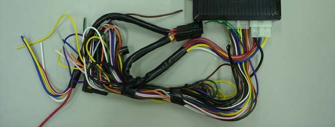
Click to zoom
Application Details
- Equipment Class
- DSR - Part 15 Remote Control/Security Device Transceiver
- Date of Grant
- Sep 30, 2007
- Application Purpose
- Original Equipment
- Date of Application
- Sep 30, 2007
- Equipment Note
- Car alarm system
- Frequency Range
- 433.92000000 - 433.92000000
- Company
- A1TECH Inc.
- Country
- South Korea
Documents & Files
Document Text
Text extracted from the exhibit documents filed with the FCC. Open a document above to read the original.
Users Manual
65K Color OLED 3D effect animation Long RF range Full-down menu Li-Polymer battery Touch unlock ■ 65K Color OLED Recharge able Li-Polymer Battery ■ ■ 3D Motion Video Long RF Range ■ ■ Touch Unlock Pull-down Menu ■ Gold Full Color 2-way Remote Car Starter & Alarm System A1Tech Inc. Note : This equipment has been tested and found to comply with the limits for a Class B digital device, pursuant to part 15 of the FCC Rules. These lim its are designed to provide reasonable protection against harmful interference in a residen tial installation. This equipment generates, uses and can radiate radio frequency energy and, if not installed and used in accordance with the instructions , may cause harmful interferenc e to radio communications. However, there is no guarantee that interference will not occur in a particular installation. If this equipment does cause harmfu l interference to radio or tele vision reception, which can be determined by turning the equipm ent off and on, the user is enc ouraged to try to correct the interference by one or more of the following measures:z Reorient or relocate the receiving antenna. z Increase the separation between the equipment and receiver. z Connect the equipment into an outlet on a circuit different fro m that to which the receiver is connected. z Consult the dealer or an experienced radio/TV technician for he lp. The device complies with Part 15 of FCC Rules.Operation is subject to the following two conditions:(1) This device may not cause harmful interference, and (2) Thi s device must accept any interference received, including interference that may cause un desired operation. Changes or modifications not expressly approved by the party re sponsible for Compliance could void the user's authority to operate the equipment.Connecting of peripherals requires the use of grounded shielded signal cables. 3 Adopted 65,000 colour Organic Light Emitting Diode (OLED). OLED is self-emissive and has the following advantages: great brightness, fast response t ime for full motion video, full viewing angles, light weight, great durability, pow er efficiency, broad operating temperature ranges. Be noted that this 3-button remot e with a built-in buzzer is not waterproof. 4 ■ This product is for DC 12V vehicles only. ■ The quality of this product is g uaranteed only when installed b y a technician of our dealer according to ins tallation instruction. ■ This alarm system is not able to protect the vehicle completely from the burglary. We hold no liability for an acci dent caused by wrong installa tion. ■ Keep the remote control dry. D o not drop or disassemble it. ■ In case of missing remote contro l contact the dealer near you t o delete the old code and input the code of new remote control.■ Pull on the hand brake of a manu al transmission vehicle on a st eep hill to prevent car accident and do not start you r car remotely. (See page 9 to c ancel the reservation. ) ■ Shock sensor may make a false al arm when a strong inducted curr ent happens like thunder or lightning. Adjust th e sensitivity of the sensors p roperly to prevent a false alarm.■ Make it sure not to use in the c losed area to prevent air-pollu tion. Do not exceed the legally permitted engine runtime. ■ This system uses low-powered rad io wave. Hence, the operating r ange may be shortened due to jamming or weather. ■ This product is designed for ins tallation in practically all ca rs. However, in case of improper installation, unfit ele ctrical system or aged cars t he system features may operate irregularly and malfunction. ■ Please note the phone number of the authorized dealer or instal ler for emergency. Remote Control Remote ∙ Lock/Unlock ∙ Panic Siren ∙ Previous Menu ∙ Status Check ∙ Select/Setup Menu ∙ Remote Start ∙ Move/Save Time ∙ Door Lock ∙ Temperature ∙ Mute ∙ Valet ∙ Proximity ∙ ∙ Battery Level ∙ Timer Start ∙ Turbo ∙ Silent Alarm ■ The images of the remote con trol are subjected to change. Before Usage ■ Power ON/OFF Press button II + III for 5 sec. to turn on/off the power. We recommend to turn off the power if you don't use the remote control for long time. In case of button lock-out, errors or freeze of the display it is recommended to re-set your remote control. Your lovely picture can be saved and displayed. Send your own image (jpg format) and the remote to near dealer. Powered by a built-in 3.7V Lithium Polymer battery.If the battery level shows one bar, charge your remote. The LED of the charger lights GREEN when the battery is full (after ca. 15 ̄30 min.). Refrain from unnecessary pressing of th e buttons to prevent rapid current consumption. Plug-in Car Charger 5 Attach the touch sensor on the front windshield. You can l ock and unlock the doors without a key or remote by fingering of t he saved 4-digit PIN on the touch sensor. ☞ See page 15 how to use. The LED in the middle indicates current status of the system . 6 Communication Module & Touch Sensor Attach the antenna (so-called Tr ansceiver) on the front windshi eld or frame. When attached on the place where the window is tinted, the oper ating range can be apparently shortened due to RF interception. ■ LED Indicator R/B flash continuously: system armed Red flashes: the vehicle is attacked Blue On: valet mode Blue flashes: auto-arming LED Off: system disarmed ω We recommended to remove stuff (like snow and mud) and to dry the part around the sensor on the front windshield. Don't use the touch sensor with the gloved finger. ■ Adjustment of the Proximity Adjust the sensitivity of the proximity ( key- less entry) by turning of the screw in themiddle. Turn it clockwise to diminish, andcounter-clockwise to increase the distance. Touch Sensor Communication Module Reset Remote Control Image Box (Optional) Charging the Battery ✔ To reset prick a pin into the small hole in the middle of the l eft side. ✔ To view the image (2 sec. long) press button II. TOUCH ω Use the supplied plug-in car charger ONLY. Otherwise, the battery could explo…
Text truncated - open the document above for the full version.
Cover Letter(s)
254-2 Oryu2-Dong, Guro-Gu, Seoul, Korea September 17, 2007 Compliance Certification Services Certification Division 561F Monterey Road Morgan Hill, CA 95037 To whom it may concern: We, the undersigned, hereby authorize the Korea Testing Lboratiory to act on our behalf in all manners relating to application for equipment authorization, including signing of all documents relating to these matters. Any and all acts carried out by CCS TW on our behalf shall have the same effect as acts of our own. We, the undersigned, hereby certify that we are not subject to a denial of federal benefits, that includes FCC benefits, pursuant to Section 5301 of the Anti-Drug Abuse Act of 1988, 21 U.S.C. 853(a). In authorizing CCS TW as our agent, we still recognize that we are responsible to: a) comply with the relevant provisions of the certification program; b) make all necessary arrangements for the conduct of the evaluation, including provision for examining documentation and access to all areas, records (including internal audit reports) and personnel for the purposes of evaluation (e.g. testing, inspection, assessment, surveillance, reassessment) and resolution of complaints; c) make claims regarding certification only in respect of the scope for which certification has been granted; d) do not use our product certification in such a manner as to bring the Certification Division into disrepute and not make any statement regarding our product certification which the Certification Division may consider misleading or unauthorized; 254-2 Oryu2-Dong, Guro-Gu, Seoul, Korea e) upon suspension or cancellation of certification, discontinue use of all advertising matter that contains any reference thereto and return any certification documents as required by the Certification Division; f) use certification only to indicate the products are certified as being in conformity with specified standards; g) endeavor to ensure that no certificate or report nor any part thereof is used in a misleading manner; h) ensure that any reference to our product certification in communication media such as documents, brochures or advertising, complies with the requirements of the Certification Division; i) keep a record of all complaints made known to the us relating to the product’s compliance with requirements of the relevant standard and to make these records available to the Certification Division when requested; j) take appropriate action with respect to such complaints and any deficiencies found in products or services that affect compliance with the requirements for certification; k) document the actions taken. This authorization is valid until further written notice from the applicant. Sincerely Yours, Beom-Taek Shim / CEO
Cover Letter(s)
A1Tech, Inc. 254-2 Oryu2-Dong, Guro-Gu, Seoul 152-902, Korea E-MAIL : [email protected] Federal Communications Commission Authorization & Evaluation Division, 7435 Oakland Mills Road Columbia, MD 21046 Attention : Equipment Authorization Branch REQUEST FOR CONFIDENTIALITY Pursuant to Sections 0.457 (d) and 0.459 of the Commission’s Rules, the Applicant hereby requests confidential treatment of some of the information accompanying this Application of FCC ID : QQ5A1GT / QQ5A1GR and as outlined below: - Block Diagram - Parts List - Circuits Description - Schematic Diagram These materials contain trade secrets and proprietary information not customarily released to the public and the public disclosure of these matters might be harmful to the Applicant and provide unjustified benefits to its competitors. The Applicant understands that pursuant to Rule 0.457(d) disclosure of this Application and all Sincerely, Date 28th of August , 2007 By : Beom-Taek Shim Title : President ============================================================
External Photos
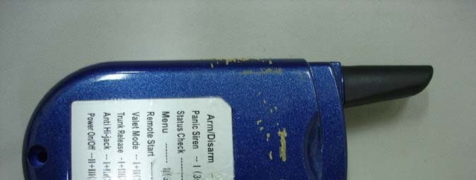
Photographs (Outside) - A1GR - <Outside – TOP> <Outside – BOTTOM
ID Label/Location Info
FCC Labeling
Internal Photos
Photographs (In-side) - A1GR - <ANTENNA PART-TOP > <ANTENNA PART-Bottom > <BODY PART- TOP > <BODY PART-Bottom >
Operational Description
Communication Protocol Format X 1 0.6mS X 2.4mS X X 5 start bit Bit Period X X 0 X X status 2.4mS 1.8mS X X X X X <'1' bit> X X dummy X X 7 start bit+81.6msec X X 1.8mS X X BitStatus 0.6mS X X 1 Command X X X 6 5.6mS X 0 4 5mS ID1 X 0.6mS X X 3 start bit X ID2 X 2 <'0' bit> 5msec 1Frame 1Frame 1Frame TX/RXMode Receiver Mode 1Frame AnswerBackTransmitter 5msec 1Frame 86.6msec 1Frame FrameFormat 0.8/3sec 1Frame 0.8/3sec Command DATA 1)0x01(DL)2)0x02(DU)3)0x03(Trunk Open)5)0x05(Engine Run)4)0x04(Engine Crank)6)0x06(Engine Run Fail) C)0x0C(Engine Run Fail)A)0x0A(Valet off) 7)0x07(Carfinder) 9)0x09(Valet on)B)0x0B(Status Fail) 8)0x08(Panic) D)0x20(Shock)E)0x40(Door Open)F)0x50(Trunk Open)G)0x60(Hood Open)
Test Report
Report No.: 07-1341-025 Page 1 of 18 Pages 222-13, Guro3-Dong Guro-Gu Seoul 152-718, Korea. Tel. : +82-2-860-1463 http://www.ktl.re.kr Fax. : +82-2-860-1468 FP-204-03-01 TEST REPORT 1. Applicant Name : A1Tech Inc. Address : 2. Products Name : Security/Remote Control transceiver(Car Alarm System) Model/Type : PROSTAR-Gold Manufacturer : A1Tech Inc. 3. Test Standard : 4. Test Method : ANSI C63.4-2003 5. Test Result : Positive 6. Date of Application : August 07, 2007 7. Date of Issue : August 29, 2007 Tested by Approved by ` Bum-Jong Kim Seok-Jin Kim Telecommunication Team Engineer Telecommunication Team Manager The test results contained apply only to the test sample(s) supplied by the applicant, and this test report shall not be reproduced in full or in part without approval of the KTL in advance. 254-2 Oryu2-Dong, Guro-Gu, Seoul, Korea FCC CFR 47 Part 15, Subpart C section 15.231(a) Report No.: 07-1341-025 Page 2 of 18 Pages 222-13, Guro3-Dong Guro-Gu Seoul 152-718, Korea. Tel. : +82-2-860-1463 http://www.ktl.re.kr Fax. : +82-2-860-1468 FP-204-03-01 TABLE OF CONTENTS I. GENERAL INFORMATION 3 1. Applicant(client) 2. Equipment(EUT) 3. Testing Laboratory II. SUMMARY OF TEST RESULTS 4 III. TEST RESULT 5 3.1 Transmitter Radiated Emissions 3.2 Bandwidth of Momentary Signals 3.3 Receiver Radiated Emissions 3.4 Conducted Emissions IV. TEST EQUIPMENTS 18 Report No.: 07-1341-025 Page 3 of 18 Pages 222-13, Guro3-Dong Guro-Gu Seoul 152-718, Korea. Tel. : +82-2-860-1463 http://www.ktl.re.kr Fax. : +82-2-860-1468 FP-204-03-01 I. GENERAL INFORMATIONS 1.1 Applicant (Client) Name A1Tech Inc. Address 254-2 Oryu2-Dong, Guro-Gu, Seoul, Korea Contact Person Zintea KIM Telephone No. +82-2-838-3006 Facsimile No. +82-2-838-3055 E-mail address [email protected] 1.2 Equipment (EUT) Type of equipment Security/Remote Control transceiver(Two-way Car Alarm System) Model Name PROSTAR-Gold FCC ID QQ5A1GR Operating Frequency 433.92 MHz Type of Signal Pulse Code Signal Power Source DC 12V (Battery) Manufacturer Name A1Tech Inc. Manufacturer Address 254-2 Oryu2-Dong, Guro-Gu, Seoul, Korea 1.3 Testing Laboratory Testing Place Korea Testing Labortory (KTL) 222-13 Guro-dong, Guro-Gu, Seoul 152-848 Korea Test Engineer Bum-Jong KIM Telephone number +82 2 860 1464 Facsimile number +82 2 860 1468 E-mail address [email protected] Other Comments - Report No.: 07-1341-025 Page 4 of 18 Pages 222-13, Guro3-Dong Guro-Gu Seoul 152-718, Korea. Tel. : +82-2-860-1463 http://www.ktl.re.kr Fax. : +82-2-860-1468 FP-204-03-01 . IISUMMARY OF TEST RESULTS The QQ5A1GR has been found to conform as detailed below. FCC Test Requirements Result 15.231(a) Provisionss of FCC 15.231 Pass 15.231(b) Transmitter Radiated Emissions – Fundamental, Harmonic and Spurious Pass 15.231(c) 20 dB Bandwidth Pass 15.109(a) Receiver Radiated Emissions Pass 15.107(a) Conducted Emissions Pass Report No.: 07-1341-025 Page 5 of 18 Pages 222-13, Guro3-Dong Guro-Gu Seoul 152-718, Korea. Tel. : +82-2-860-1463 http://www.ktl.re.kr Fax. : +82-2-860-1468 FP-204-03-01 III. TEST RESULTS 3.1. Transmitter Spurious Emissions (FCC Part 15.231(a)) 3.1.1 Test procedure 3.1.1.1 Preliminary Testing for Reference Preliminary testing was performed in a KTL absorber-lined room to determine the emission characteristics of the EUT. The EUT was placed on the wooden table which has dimensions of 0.8 meters in height, 1 meter in length and 1.5 meters in width. Receiving antenna (Biconi-Log antenna : 30 to 1000 MHz or Horn Antenna : 1 to 18 GHz) was placed at the distance of 1 meter from the EUT. An attempt was made to maximize the emission level with the various configurations of the EUT while rotating the table and varying antenna height. Emissions level from the EUT with various configurations were examined on a Spectrum Analyzer connected with an RF amplifier and graphed by a plotter. 3.1.1.2 Final Radiated Emission Test at an Absorber-Lined Room The final measurement of radiated field strength was carried out in a KTL Absorber-Lined Room that was listed up at FCC according to the "Radiated Emissions Testing" procedure specified by ANSI C63.4. Based on the test results in preliminary test, measurement was made in same test set up and configuration which produced maximum emission level. Receiving antenna was installed at 3-meter distance from the EUT, and was connected to an EMI receiver. Receiving antenna polarization was changed vertical and horizontal. The worst value was recorded. Turntable was rotated through 360 degrees and receiving antenna height was varied from 1 to 4 meters above the ground plane to read maximum emission level. If necessary, the radiated emission measurements could be performed at a closer distance than specified distance to ensure higher accuracy and their results were extrapolated to the specified distance using an inverse linear distance extrapolation factor (20 dB/decade) as per Section 15.31(f). The maximum emission level from the EUT occurred in such configuration as shown in the following photograph. Report No.: 07-1341-025 Page 6 of 18 Pages 222-13, Guro3-Dong Guro-Gu Seoul 152-718, Korea. Tel. : +82-2-860-1463 http://www.ktl.re.kr Fax. : +82-2-860-1468 FP-204-03-01 3.1.2. Photograph for the test configuration 3.1.3 Limit Fundamental Field Strength of Field Strength of Frequency Fundamental Spurious Emission (MHz) (microvolts/meter) (microvolts/meter) ------------------------------------------------------------------------------------------------------------------------- 40.66–40.70 1,000 100 70-130 500 50 130-174 500 to 1,500** 50 to 150** 174-260 1,500 150 260-470 1,500 to 5,000** 150 to 500** Above 470 5,000 500 -------------------------------------------------------------------------------------------------------------------------- ** linear interpolations [Where F is the frequency in MHz, the formulas for calculating the maximum permitted fundamental field strengths are as follows : for the band 130-174 MHz, Uv/m at 3 meters = 22.72727(F)-2454.545; for t…
Text truncated - open the document above for the full version.
Test Setup Photos
TEST Photographs < Radiated emission – Front - 1 > < Radiated emission – Front - 2 > < Radiated emission – Front - 3 > < Radiated emission – Rear > <Conducted emission – Front > < Conducted emission – Rear >
Contact Information
Applicant
Beom-Taek Shim(President)
Test Firm
Korea Testing LaboratoryJeong-Min Kim
Technical Specifications
| # | Rule Parts | Frequency Range | Power Output |
|---|---|---|---|
| 1 | 15.231 | 433.92 MHz - 433.92 MHz | - |
Other Applications from A1TECH Inc.
QQ5A1GT
Sep 30, 2007Car Alaram
Equipment Class
DSR - Part 15 Remote Control/Security Device Transceiver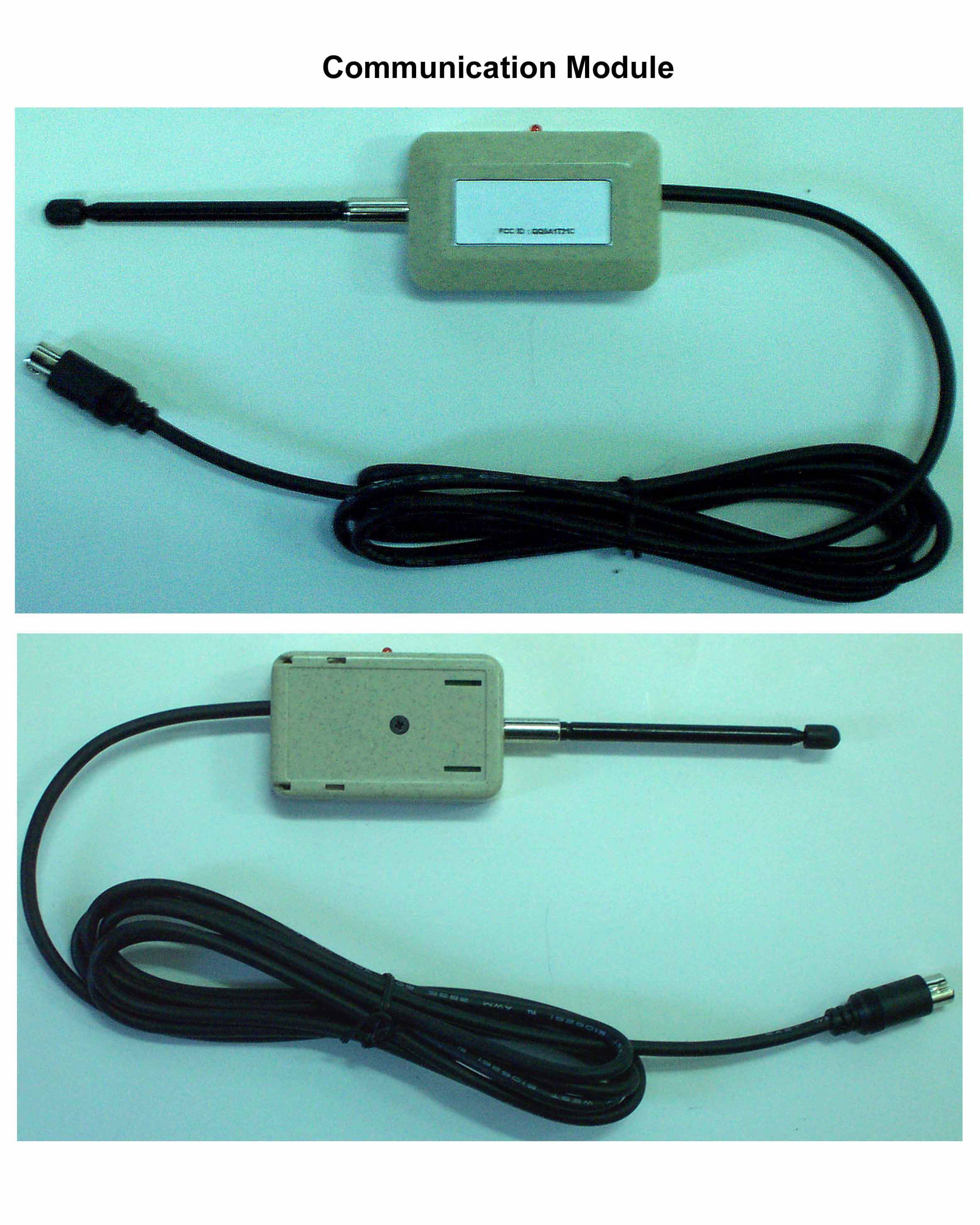
QQ5A1T21C
Jan 21, 2003Two Way Car Alarm System
Equipment Class
DSR - Part 15 Remote Control/Security Device Transceiver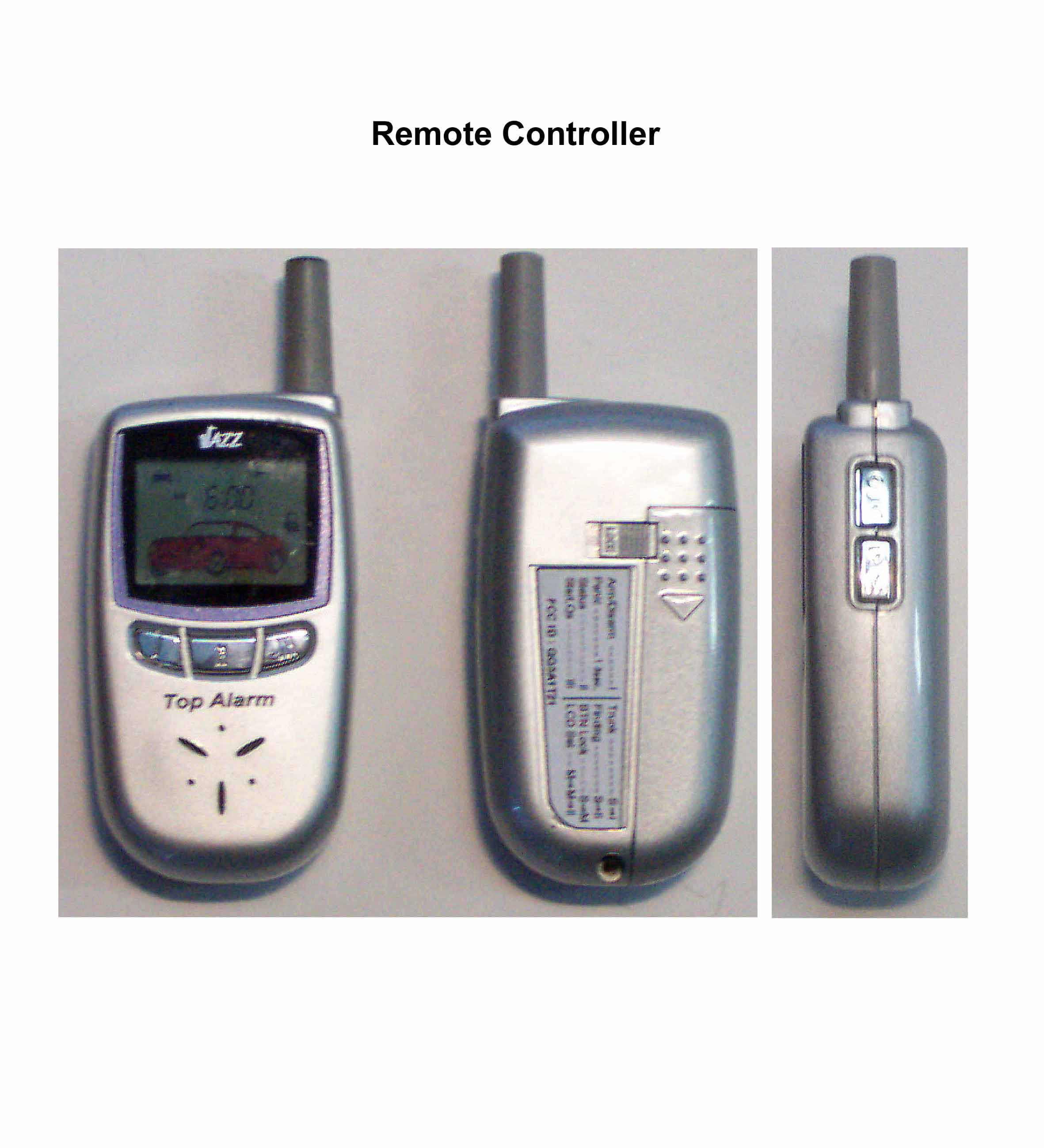
QQ5A1T21
Jan 21, 2003Two Way Car Alarm System
Equipment Class
DSR - Part 15 Remote Control/Security Device Transceiver