QQ5A1T21Two Way Car Alarm System
A1TECH Inc.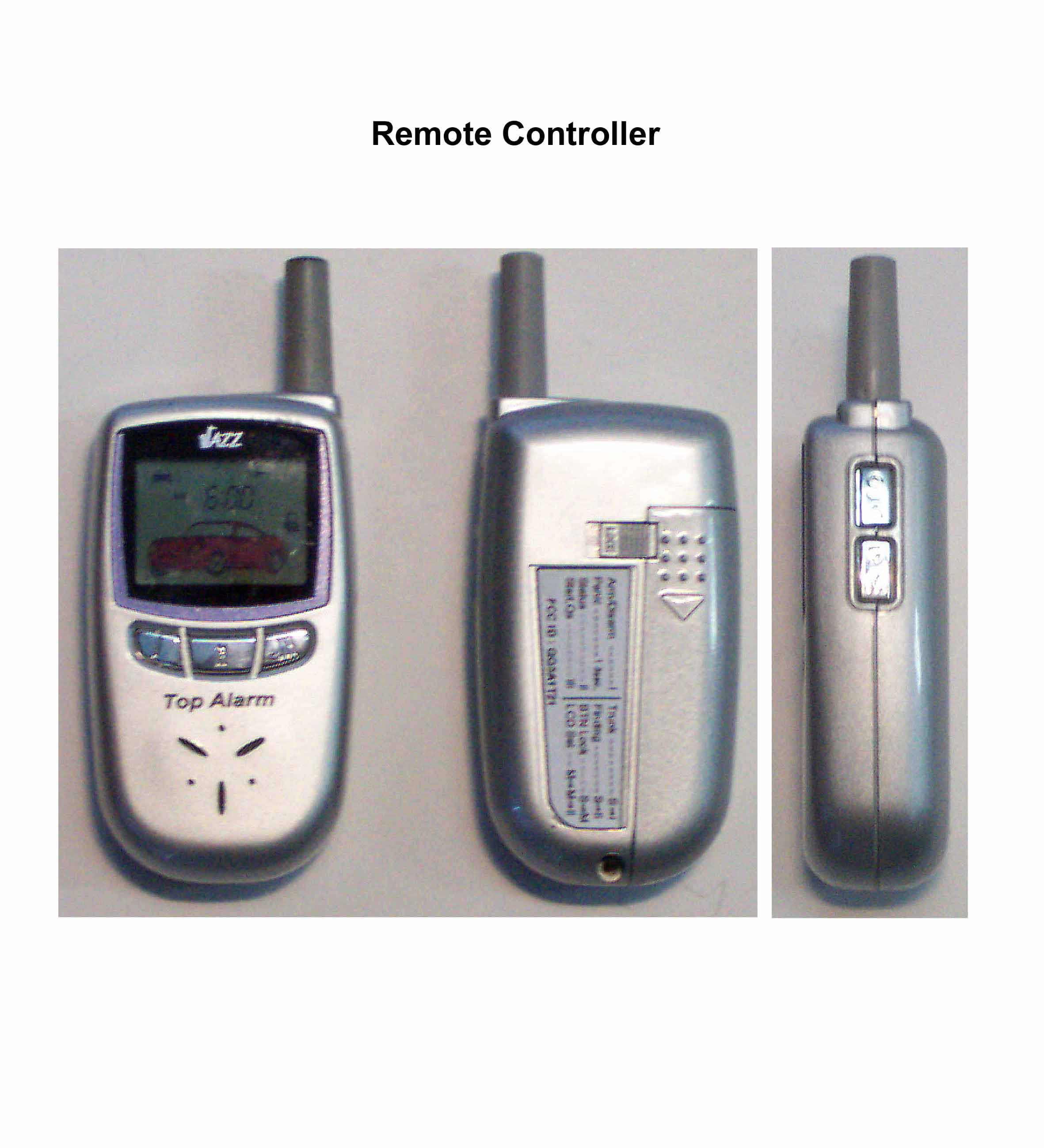
Click to zoom
Application Details
- Equipment Class
- DSR - Part 15 Remote Control/Security Device Transceiver
- Date of Grant
- Jan 21, 2003
- Application Purpose
- Original Equipment
- Date of Application
- Jan 21, 2003
- Equipment Note
- Two Way Car Alarm System
- Frequency Range
- 433.92000000 - 433.92000000
- Company
- A1TECH Inc.
- Country
- South Korea
Documents & Files
Document Text
Text extracted from the exhibit documents filed with the FCC. Open a document above to read the original.
Users Manual
This device complies with part 15 of the FCC Rules. Operation is subject to the following two conditions: (1) This device may not cause harmful interference, and (2) this device must accept any interference received, including interference that may cause undesired operation. Caution : Any changes or modifications in construction of this device which are not expressly approved by the party responsible for compliance could void the users authority to operate the equipment. Two-Way Communication Vehicle Security and Remote Convenience System With Remote Engine Start and Paging System OWNERS GUIDE OWNERS GUIDE A1Tech Inc. Before Usage3 System Components4 Basic Function7 Locking the Door / Arming the System Unlocking the Door / Disarming the System Trunk Release Vehicle Locator Emergency Panic Alarm Vibrate Mode Alarm Clock Optional Feature Control Button Lockout Triggering the Alarm Driver paging Quick-service Engine Start Features13 Remote Engine Start Programmable Timed Remote Engine Start Remote Start for Manual Transmission Vehicles Entering the Vehicle During Remote Engine Start Cold Weather Start Convenience Features15 Automatic Door Lock / Unlock Controlled by lgnition Hidden Alarm Mute Chirp Sound Turbo Funtion 1 Contents Starter Interrupt Dome Light Control Use of One-way Remote Control Setting Time17 Setting the Clock Time Setting Programmed Remote Start Time Setting Alarm Clock Time System 1 Programming18 Chirp Sound Mute On/Off Passive Arming On/Off Passive Door Lock On/Off Last Door Arming On/Off Ignition Control Door On/Off System 2 Programming 20 Alarm Sound Duration Setting Remote Start Run Time Setting TurboTime Cold Weather Start Time Technical Support 21 Manual Valet Mode Valet Mode by Push Switch Code Programming System Intializing System Shutoff System Troubleshooting24 2 Contents 3 You are mostly welcome to purchase JAZZVehicle Alarm & Starter System, World wide Top Quality Product ! JAZZwill surely keep your vehicle from theft and outside impact in safety for 24 hours and provide you with various convenience and comfort. You are kindly recommended to read Owners Guide thoroughly and refer to it whenever you encounter any inquiry by keeping it always in the vehicle. Please contact the dealer nearby you when you need a solution and technical advice during usage. Keep the Remote Control dry and do not drop and disassemble it. When the Remote Control is lost, please contact the dealer nearby you and delete the code number for the purpose of anti-theft. Then, purchase new Remote Control and input new code number for usage. Please make it sure never to use Remote Engine Start in the closed area. Before Usage JAZZ-IIhas no Remote engine start function(Remote engine start, Programmable timed remote engine start, Cold weather start, Quick service). Engine Start Module can be installed optionally for Remote engine start. If you want to add this function, please discuss with the dealer nearby you. 4 With 3 buttons on the facade and 2 buttons on the side, it contains color LCD screen, TX/RX electronic circuit, highly efficient speaker for original sound and vibration motor. User can discern easily the current status of the vehicle and the system with each sound because it makes different sounds according to each function, reviving the natural sounds like various kinds of voices and music melody and engine-starting sound (brrung). Especially, E/L back light for illuminating a dark place and clock function are built in as additional apparatuses. Remote Control Battery Replacement Remote Control is operated by 1 x Alkaline 1.5V LR03 AAA.When icon on the screen appears with beep sound, change the battery. When the old battery is replaced to new one, Remote Control sounds melody, illuminates light on the screen and vibrates. Then, the clock returns to AM12:00 after displaying all the icons one after another. Please use JAZZ after setting the clock to present time and checking the current status by pressing I button. System Components III Button II Button I Button S Button M Button 5 System Components It transfers signal to/from Remote Control and is plugged into the Control Module. Knock Sensor and Warning LED are built-in. By adjusting screw on the side part, you can set the sensitivity of the Knock Sensor to strong or week position properly, i.e. sensitivity will be increased by turning screw clockwise and decreased by turning it counterclockwise. Communication Module Communication Range Check By pressing button II, you can also check if your Remote Control is within the range of transmission or not. If within the range, the current status of system (Arm or Disarm) appears on the LCD screen with melody sounding. If out of the range, icon disappear with relevant melody sounding. With communication by low-powered radio wave of JAZZ, the operating range may be extremely shortened due to the existence of same frequency of wireless radio nearby and electric wave disturbance. Press II 6 System Components Because of the two-way communication capability, sometimes it does not operate immediately upon pressing the button. So, please operate again for its not products defect. Press the button for one second if there is no other special instruction. To see if the area is available zone for communicating with the vehicle or not, press II button. In case melody emits from the Remote Control, with the word “System is Okay” communication is available for range. How to Communicate (Operation method) Sound Vibrate mode Digital clock Alarm clock Shock sensing Mute chirp RF range verification Battery low warning Door lock status Engine running Trunk open Door open System valet Light flashing Arming status Programmable start Optional function Hood open 7 Basic Functions Locking the Doors / Arming the System If all doors are not closed when the system is armed, the alarm will sound. If the system is in Valet mode, the doors will lock and unlock, but the alarm function will remain inactive. The alarm beco…
Text truncated - open the document above for the full version.
Cover Letter(s)
From: Jeong-Min Kim Sent: Wednesday, January 22, 2003 4:51 AM To: Mike Kuo Subject: Re: A1TECH Inc., FCC ID:QQ5A1T21, An03T2508 Dear Mr. Mike I attached revised test report , label format, external photo and user's manual. Thank you for your cooperation. Best Regards, Jeongmin kim ************************************************ Jeong-Min Kim ************************************************ ----- Original Message ----- From: "Mike Kuo" <[email protected]> Sent: Tuesday, January 21, 2003 12:15 PM Subject: FW: A1TECH Inc., FCC ID:QQ5A1T21, An03T2508 > > > -----Original Message----- > From: CERTADM > Sent: Monday, January 20, 2003 7:07 PM > To: '[email protected]' > Subject: A1TECH Inc., FCC ID:QQ5A1T21, An03T2508 > > > Notice_content > ------------- > Question #1: This transmitter portion of transceiver is pulse code. Per > section 15.35( c ) requirement, "when the limit is specified as average and > the pulsed operation is employed, the measurement field strength shall be > determined by averaging over one complete pulse train. . . .". For Pulse > modulation, you can not use average detector to obtain the average reading. > You shall find out the duty cycle of transmitter and correct the peak > reading to obtain the average reading. Average reading= Pk Reading + > 20*log(M%). M% is the modulation percentage. In this application, the peak > reading is over the average limit so the average reading in using about > method is required. When you submit additional average reading with duty > cycle correction factor, please also provide duty cycle plots . > > Question #2: The FCC ID label format and User manual are using FCC DoC logo. > Please note, the FCC DoC logo does not apply for transmitter device. The > receiver portion of transceiver is subject to verification only. Please > provide revised FCC ID label format. > > Best Regards > > Mike Kuo > The items indicated above must be submitted before processing can continue > on the above referenced application. Failure to provide the requested > information within 60 days of the original e-mail date may result in > application dismissal and forfeiture of the filing fee. Also, please note > that partial responses increase processing time and should not be submitted. > Any questions about the content of this correspondence should be directed to > the e-mail address listed below the name of the sender. > >
Test Report
KTL Korea Testing Laboratory Page 1 of 11 TEST REPORT This test report only responds to the tested sample and shall not be reproduced except in full without written approval of the Korea Testing Laboratory. Tested and reported by Reviewed by Jeong-Min Kim, Senior Engineer Hee-Soo Kim , Telecommunication Team Manager KOREA TESTING LABORATORY FG101-01-02-00 222-13, Guro-Dong Guro-Gu Seoul Korea 152-053 http://www.ktl.re.kr Ref. Report No. 02-341-051-01 Name and address of the applicant A1TECH Inc. 5F, #158-847 Kwangmyeong 4-Dong Kwangmyeong-Shi, Gyeonggi-Do, 423-858 Korea Standard / Test regulation FCC Part 15, Subpart C Test result Pass Incoming date : December 2, 2002 Test item(s) ; Remote Control/ Security Device Transceiver (Transmitter Portion) (Two Way Car Alarm System / Remote) Model/type ref. ; JAZZ Manufacturer ; A1TECH Inc. Additional information ; -Required Authorization : Certification -FCC ID. : QQ5A1T21 -Note : Test report(Verification) of Receiver portion of this unit is issued on Ref. Report No. 02-341-051-02. Test date : January 4, 2003 Issue date : January 4, 2003 Ref. Report No. 02 - 341 – 051 - 01 Page 2 of 14 Korea Testing Laboratory Telecommunication Team 222-13, Guro3-dong, Guro-gu, Seoul Korea 152-848 TABLE OF CONTENTS I. GENERAL INFORMATION 3 1. Grantee’s Name and Mailing Address 2. Manufacturer's Name and Mailing Address 3. Equipment Descriptions 4. Rules and Regulations 5. Measuring Procedure 6. Place of Measurement 7. Date of Measurement . GENERAL REQUIREMENTS OF THE EUT 4 1. Labeling Requirement (Section 15.19) 2. Information to User (Sections 15.21) 3. Special Accessories (Section 15.27) 4. Compliant Conditions (Section 15.231) . RADIATED EMISSION MEASUREMENT (Section 15.231) 6 1. Test Procedure 2. Photograph of the test configuration 3. Sample Calculation 4. Measurement Data 5. Reference Data . OCCUPIED BANDWIDTH MEASUREMENT (Section 15.231) 10 . TEST EQUIPMENTS USED FOR MEASUREMENT 11 Ref. Report No. 02 - 341 – 051 - 01 Page 3 of 14 Korea Testing Laboratory Telecommunication Team 222-13, Guro3-dong, Guro-gu, Seoul Korea 152-848 . GENERAL INFORMATION 1. Grantee’s Name and : A1TECH Inc. Mailing Address 5F, #158-847 Kwangmyeong 4-Dong, Kwangmyeong-Shi, Gyeonggi-Do, 423-858 Korea 2. Manufacturer's Name and : A1TECH Inc. Mailing Address 5F, #158-847 Kwangmyeong 4-Dong, Kwangmyeong-Shi, Gyeonggi-Do, 423-858 Korea 3. Equipment Descriptions 3.1 Operating Frequency : 433.92 MHz 3.2 Type of Emission : Pulse Code Signal (FSK) 3.3 Power Supply : DC 1.5 V(AAA Battery) 4. Rules and Regulations : FCC Part 15, Subpart C 5. Measuring Procedure : ANSI C63.4-1992 6. Place of Measurement : Absorber-lined Room (KTL) 7. Date of Measurement 7.1 Conducted Emission : Not Applicable 7.2 Radiated Emission : January 4, 2003 Ref. Report No. 02 - 341 – 051 - 01 Page 4 of 14 Korea Testing Laboratory Telecommunication Team 222-13, Guro3-dong, Guro-gu, Seoul Korea 152-848 . GENERAL REQUIREMENTS OF THE EUT 1. Labeling Requirement (Section 15.19) This device complies with Part 15 of the FCC Rules. Operation is subject to the following two conditions: (1) this device may not cause harmful interface, and (2) this device must accept any interference received, including interference that may cause undesired operation. 1.1 Location of Label : User’s Guide Manual 1.2 How Applied : Printed 2. Information to User (Section 15.21) The following or similar statements were provided in the manual for user instruction. Please refer page 1 of the attached manual for details. CAUTION : Any changes or modifications in construction of this device which are not expressly approved by the party responsible for compliance could void the user's authority to operate the equipment. 3. Special Accessories (Section 15.27) 3.1 Were the special Accessories provided? [ ] yes, [ x ] no 3.2 If yes, details for the special accessories are as follows : 3.3 If yes, were the appropriate instructions provided on the first page of the text concerned with the installation of the device? [ ] yes, [ ] no 3.4 Are these accessories provided of the type which can be readily obtained from multiple retail outlets ? [ ] yes, [ ] no And therefore does the manual specify what additional components or accessories are required to used in order to comply with the Rules? [ ] yes, [ ] no Ref. Report No. 02 - 341 – 051 - 01 Page 5 of 14 Korea Testing Laboratory Telecommunication Team 222-13, Guro3-dong, Guro-gu, Seoul Korea 152-848 4. Compliant Conditions (Section 15.231) 4.1 Was the EUT used for continuous transmissions, such as voice or video, and data transmission ? [ ] yes, [ x ] no 4.2 Was the EUT manually operated ? [ x ] yes, [ ] no If yes, did the EUT employ a switch that would automatically deactivate the transmitter within not more than 5 seconds of being released ? [ x ] yes, [ ] no 4.3 Was the EUT automatically activated ? [ ] yes, [ x ] no If yes, did the EUT cease transmission within 5 seconds after deactivation ? [ ] yes, [ ] no 4.4 Was the EUT used for periodic transmissions at regular predetermined intervals ? [ ] yes, [ x ] no Ref. Report No. 02 - 341 – 051 - 01 Page 6 of 14 Korea Testing Laboratory Telecommunication Team 222-13, Guro3-dong, Guro-gu, Seoul Korea 152-848 . RADIATED EMISSION MEASUREMENT (Section 15.231) 1. Test Procedure 1.1 Preliminary Testing for Reference Preliminary testing was performed in a KTL absorber-lined room to determine the emission characteristics of the EUT. The EUT was placed on the wooden table which has dimensions of 0.8 meters in height, 1 meter in length and 1.5 meters in width. Receiving antenna (Biconical antenna : 30 to 300 MHz, Log-periodic antenna : 200 to 1000 MHz or Horn Antenna : 1 to 18 GHz) was placed at the distance of 1 meter from the EUT. An attempt was made to maximize the emission level with the various configurations of the EUT. Emission levels from the EUT with various configurations were examined on a spectrum analyzer connected with a RF amplifier and graphed by a plot…
Text truncated - open the document above for the full version.
Test Setup Photos
Ref. Report No. 02 - 341 – 051 - 01 Page 8 of 11 Korea Testing Laboratory Telecommunication Team 222-13, Guro3-dong, Guro-gu, Seoul Korea 152-848 2. Photograph of the test configuration 3. Sample Calculation The emission level measured in decibels above one microvolt (dB) was converted into microvolt per meter (/m) as shown in following sample calculation. For example : Measured Value at 433.9 MHz 41.7 dB + Antenna Factor 16.1 dB/m + Cable Loss 4.1 dB Preamplifier 0.0 dB Distance Correction Factor * 0.0 dB ------------------------------------------------------------------------------------------- = Radiated Emission 61.9 dB/m ( = 1244.5/m ) * Extrapolated from the measured distance to the specified distance by an inverse linear distance extrapolation.
Contact Information
Applicant
Beom-Taek Shim(President)
Test Firm
Korea Testing LaboratoryJeong-Min Kim
Technical Specifications
| # | Rule Parts | Frequency Range | Power Output |
|---|---|---|---|
| 1 | 15.231 | 433.92 MHz - 433.92 MHz | - |
Other Applications from A1TECH Inc.
QQ5A1GT
Sep 30, 2007Car Alaram
Equipment Class
DSR - Part 15 Remote Control/Security Device Transceiver
QQ5A1GR
Sep 30, 2007Car alarm system
Equipment Class
DSR - Part 15 Remote Control/Security Device Transceiver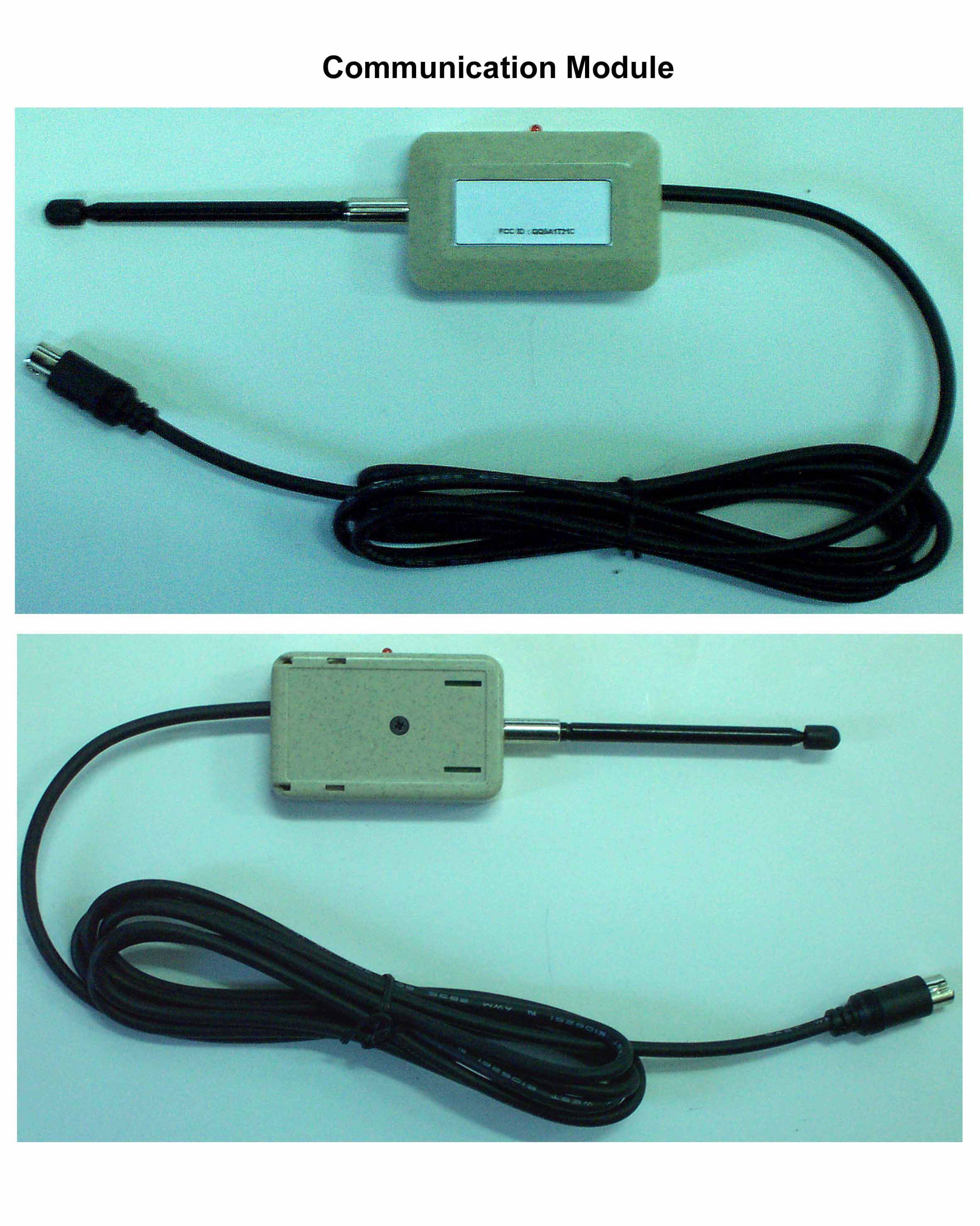
QQ5A1T21C
Jan 21, 2003Two Way Car Alarm System
Equipment Class
DSR - Part 15 Remote Control/Security Device Transceiver