QQ6-BTC01CHARGING STATION WITH BLUETOOTH
Code Corporation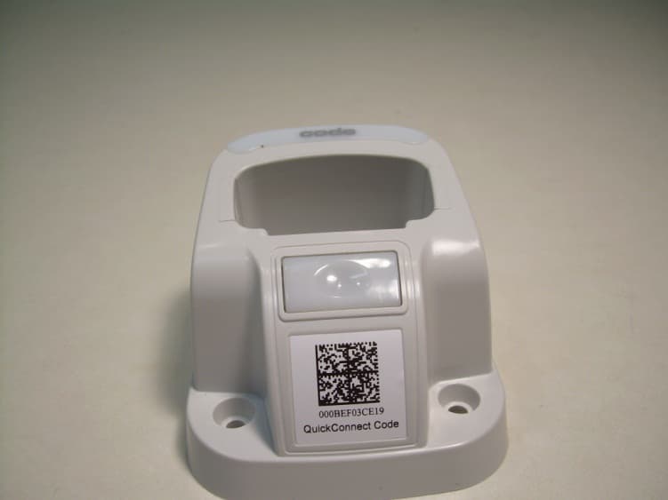
Click to zoom
Application Details
- Equipment Class
- DSS - Part 15 Spread Spectrum Transmitter
- Date of Grant
- Feb 12, 2013
- Application Purpose
- Original Equipment
- Date of Application
- Feb 12, 2013
- Equipment Note
- CHARGING STATION WITH BLUETOOTH
- Frequency Range
- 2402.00000000 - 2480.00000000
- Company
- Code Corporation
- Country
- United States
Documents & Files
Document Text
Text extracted from the exhibit documents filed with the FCC. Open a document above to read the original.
Users Manual
C007964_04_CR2600_User_Manual C007964_04_CR2600_UserManual User Manual Code Reader™ 2600 Manual Version 04 Release Date: February 2013 C007964_04_CR2600_User_Manual Statement of Agency Compliance The Code Reader™ 2600 (CR2600) has been tested for compliance with FCC regulations and was found to be compliant with all applicable FCC Rules and Regulations. IMPORTANT NOTE: To comply with FCC RF exposure compliance requirements, this device must not be co-located or operate in conjunction with any other antenna or transmitter. CAUTION: Changes or modifications not expressly approved by the party responsible for compliance could void the user’s authority to operate the equipment. The CR2600 has been tested for compliance to CE standards and guidelines and was found to conform to applicable CE standards, specifically the EMC requirements EN 55024, ESD EN 61000-4-2, Radiated RF Immunity EN 61000-4-3, ENV 50204, EFT EN 61000-4-4, Conducted RF Immunity EN 61000-4-6, EN 55022, Class B Radiated Emissions, and Class B Conducted Emissions. The CR2600 has been tested and certified in compliance with the Technical Regulations Conformity Certification of Specified Radio Equipment (ordinance of MPT N°.37. 1981), Article 2, Paragraph 1, Item 19. Code voids product warranty if the hard case has been opened or tampered with in any way. The CR2600 meets all safety and quality standards in accordance to EN 60950-1:2006/A11:2009/A1:2010. CR2600 CodeXML® Modem FCC and ICES Compliance NOTE: This equipment has been tested and found to comply with the limits for a Class B digital device, pursuant to part 15 of the FCC Rules. These limits are designed to provide reasonable protection against harmful interference in a residential installation. This equipment generates, uses and can radiate radio frequency energy and, if not installed and used in accordance with the instructions, may cause harmful interference to radio communications. However, there is no guarantee that interference will not occur in a particular installation. If this equipment does cause harmful interference to radio or television reception, which can be determined by turning the equipment off and on, the user is encouraged to try to correct the interference by one or more of the following measures: • Reorient or relocate the receiving antenna. • Increase the separation between the equipment and receiver. • Connect the equipment into an outlet on a circuit different from that to which the receiver is connected. • Consult the dealer or an experienced radio/TV technician for help. This device complies with part 15 of the FCC Rules. Operation is subject to the following two conditions: (1) This device may not cause harmful interference, and (2) this device must accept any interference received, including interference that may cause undesired operation. This device complies with Industry Canada licence-exempt RSS standard(s). Operation is subject to the following two conditions: (1) this device may not cause interference, and (2) this device must accept any interference, including interference that may cause undesired operation of the device. Le présent appareil est conforme aux CNR d’Industrie Canada applicables aux appareils radio exempts de licence. L’exploitation est autorisée aux deux conditions suivantes : (1) l’appareil ne doit pas produire de brouillage, et (2) l’utilisateur de l’appareil doit accepter tout brouillage radioélectrique subi, même si le brouillage est susceptible d’en compromettre le fonctionnement. This Class B digital apparatus complies with Canadian ICES-003. Cet appareil numérique de la classe B est conforme à la norme NMB-003 du Canada. C007964_04_CR2600_User_Manual Code Reader™ 2600 User Manual Copyright © 2013 Code Corporation. All Rights Reserved. The software described in this manual may only be used in accordance with the terms of its license agreement. No part of this publication may be reproduced in any form or by any means without written permission from Code Corporation. This includes electronic or mechanical means such as photocopying or recording in information storage and retrieval systems. NO WARRANTY. This technical documentation is provided AS-IS. Further, the documentation does not represent a commitment on the part of Code Corporation. Code Corporation does not warrant that it is accurate, complete or error free. Any use of the technical documentation is at the risk of the user. Code Corporation reserves the right to make changes in specifications and other information contained in this document without prior notice, and the reader should in all cases consult Code Corporation to determine whether any such changes have been made. Code Corporation shall not be liable for technical or editorial errors or omissions contained herein; nor for incidental or consequential damages resulting from the furnishing, performance, or use of this material. Code Corporation does not assume any product liability arising out of or in connection with the application or use of any product or application described herein. NO LICENSE. No license is granted, either by implication, estoppel, or otherwise under any intellectual property rights of Code Corporation. Any use of hardware, software and/or technology of Code Corporation is governed by its own agreement. The following are trademarks or registered trademarks of Code Corporation: CodeXML®, Maker, QuickMaker, CodeXML® Maker, CodeXML® Maker Pro, CodeXML® Router, CodeXML® Client SDK, CodeXML® Filter, HyperPage, CodeTrack, GoCard, GoWeb, ShortCode, GoCode®, Code Router, QuickConnect Code, Rule Runner®, Cortex®, CortexRM, CortexMobile, Code, Code Reader, CortexAG, CortexStudio, CortexTools, Affinity®, CortexDecoder, CortexJPOS, and CortexOPOS. All other product names mentioned in this manual may be trademarks of their respective companies and are hereby acknowledged. The software and/or products of Code Corporation include inventions that are patented or that are the subject of patent…
Text truncated - open the document above for the full version.
External Photos
Front View of the EUT Back View of the EUT
ID Label/Location Info
CRA-A104 Serial Label Samples CRA-A104 Serial Label Sample CRA-A104 CODE (Manufacturer Name) Label Sample
ID Label/Location Info
CRA-A104 Label Placement CRA-A104 Serial Label Placement CODE (MFG Name) Label Placement CRA-A104 Bottom View CRA-A104 Top View
Internal Photos
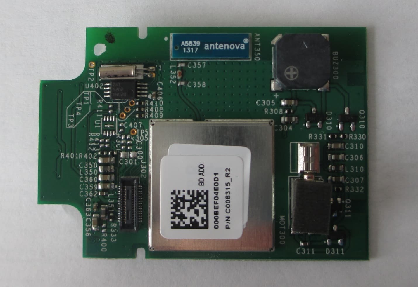
Internal View Front of the EUT Top View of the PCB with RF Shield Removed View of the Bottom Side of the PCB
Test Report
Nemko-CCL, Inc. 1940 West Alexander Street Salt Lake City, UT 84119 801-972-6146 Test Report Certification Test Of: CRA-A104 FCC ID: QQ6-BTC01 Test Specification: FCC PART 15, Subpart C Test Report Serial No: 218101-2.2 Applicant: Code Corporation 14870 South Pony Express Rd., Suite 200 Bluffdale, UT 84065 Dates of Test: June 25, 26 & 28, 2012 Report Issue Date: August 28, 2012 Accredited Testing Laboratory By: NVLAP Lab Code 100272-0 Nemko-CCL, Inc. TEST REPORT: 218101-2.2 REPORT ISSUE DATE: 08/28/2012 Page 2 of 53 CERTIFICATION OF ENGINEERING REPORT This report has been prepared by Nemko-CCL, Inc. to document compliance of the device described below with the requirements of Federal Communications Commission (FCC) Part 15, Subpart C. This report may be reproduced in full, partial reproduction may only be made with the written consent of the laboratory. The results in this report apply only to the sample tested. - Applicant: Code Corporation - Manufacturer: Technocom Systems Sdn. Bhd. - Brand Name: Code - Model Number: CRA-A104 - FCC ID Number: QQ6-BTC01 On this 28 th day of August 2012, I, individually, and for Nemko-CCL, Inc., certify that the statements made in this engineering report are true, complete, and correct to the best of my knowledge, and are made in good faith. Although NVLAP has recognized that the Nemko-CCL, Inc. EMC testing facilities are in good standing, this report must not be used to claim product certification, approval, or endorsement by NVLAP, NIST, or any agency of the federal government. Nemko-CCL, Inc. Tested by: Norman P. Hansen EMC Technician Reviewed by: Thomas C. Jackson General Manager Nemko-CCL, Inc. TEST REPORT: 218101-2.2 REPORT ISSUE DATE: 08/28/2012 Page 3 of 53 TABLE OF CONTENTS PAGE SECTION 1.0 CLIENT INFORMATION .................................................................................4 SECTION 2.0 EQUIPMENT UNDER TEST (EUT)..................................................................5 SECTION 3.0 TEST SPECIFICATION, METHODS & PROCEDURES ...........................10 SECTION 4.0 OPERATION OF EUT DURING TESTING..................................................16 SECTION 5.0 SUMMARY OF TEST RESULTS ...................................................................17 SECTION 6.0 MEASUREMENTS, EXAMINATIONS AND DERIVED RESULTS ..........18 APPENDIX 1 TEST PROCEDURES AND TEST EQUIPMENT .........................................37 APPENDIX 2 PHOTOGRAPHS ................................................................................................43 Nemko-CCL, Inc. TEST REPORT: 218101-2.2 REPORT ISSUE DATE: 08/28/2012 Page 4 of 53 SECTION 1.0 CLIENT INFORMATION 1.1 Applicant: Company Name: Code Corporation 14870 South Pony Express Rd., Suite 200 Bluffdale, UT 84065 Contact Name: Ryan Hoobler Title: Director of Engineering 1.2 Manufacturer: Company Name: Technocom Systems Sdn. Bhd. NO. 2, Jalan Kempas 5/2, Tampoli Johor Bahru, Johor, Malaysia Contact Name: TS Wong Title: Program Manager Nemko-CCL, Inc. TEST REPORT: 218101-2.2 REPORT ISSUE DATE: 08/28/2012 Page 5 of 53 SECTION 2.0 EQUIPMENT UNDER TEST (EUT) 2.1 Identification of EUT: Brand Name: Code Corporation Model Number: CRA-A104 Serial Number: Engineering Unit Dimensions: 11.4 x 8.25 x 6.4 cm Country of Manufacture: Malaysia 2.2 Description of EUT: The CRA-A104 is a charging station for CR2600 series handheld barcode scanners. The CRA-A104 may be powered by a Group West 6UA-05-1200 external 5 VDC adapter or from a device with a USB port. A Bluetooth transceiver is incorporated to transfer data to a host system. The Bluetooth transceiver uses 79 channels in the 2400 to 2483.5 MHz frequency band. The transceiver uses a Tyco 1513349-1 embedded antenna that is soldered to the PCB. Plots of the channels are shown below. dBm 0.5 -9.5 -19.5 -29.5 -39.5 -49.5 -59.5 -69.5 -79.5 -89.5 -99.5 Trace A Start: 2.4010 GHzStop: 2.4218 GHz 6/26/2012 1:36:13 PMESU-40Atten: 35 dB Trace Alower 20 channels Mkr Trace X-Axis Value 1 1 Trace A 2.4020 GHz-1.33 dBm 2 2 Trace A 2.4030 GHz-1.72 dBm 3 3 Trace A 2.4040 GHz-1.78 dBm 4 4 Trace A 2.4050 GHz-0.98 dBm 5 5 Trace A 2.4060 GHz-2.11 dBm 6 6 Trace A 2.4070 GHz-2.14 dBm 7 7 Trace A 2.4080 GHz-1.77 dBm 8 8 Trace A 2.4090 GHz-0.98 dBm 9 9 Trace A 2.4100 GHz-0.95 dBm 10 10 Trace A 2.4110 GHz-2.12 dBm 11 11 Trace A 2.4120 GHz-2.26 dBm 12 12 Trace A 2.4130 GHz-1.24 dBm 13 13 Trace A 2.4140 GHz-1.12 dBm 14 14 Trace A 2.4150 GHz-1.55 dBm 15 15 Trace A 2.4160 GHz-0.91 dBm 16 16 Trace A 2.4170 GHz-1.03 dBm 17 17 Trace A 2.4180 GHz-1.01 dBm 18 18 Trace A 2.4190 GHz-2.62 dBm 19 19 Trace A 2.4200 GHz-1.66 dBm 20 20 Trace A 2.4210 GHz-1.57 dBm Nemko-CCL, Inc. TEST REPORT: 218101-2.2 REPORT ISSUE DATE: 08/28/2012 Page 6 of 53 dBm 10 0 -10 -20 -30 -40 -50 -60 -70 -80 -90 Trace A Start: 2.4218 GHzStop: 2.4418 GHz 6/26/2012 1:38:54 PMESU-40Atten: 35 dB Trace Amiddle lower 20 channels Mkr Trace X-Axis Value 1 1 Trace A 2.4220 GHz-1.16 dBm 2 2 Trace A 2.4230 GHz-1.61 dBm 3 3 Trace A 2.4240 GHz-1.57 dBm 4 4 Trace A 2.4250 GHz-1.42 dBm 5 5 Trace A 2.4260 GHz-0.94 dBm 6 6 Trace A 2.4270 GHz-2.19 dBm 7 7 Trace A 2.4280 GHz-1.47 dBm 8 8 Trace A 2.4290 GHz-1.83 dBm 9 9 Trace A 2.4300 GHz-1.53 dBm 10 10 Trace A 2.4310 GHz-1.46 dBm 11 11 Trace A 2.4320 GHz-1.31 dBm 12 12 Trace A 2.4330 GHz-1.76 dBm 13 13 Trace A 2.4340 GHz-0.78 dBm 14 14 Trace A 2.4350 GHz-1.77 dBm 15 15 Trace A 2.4360 GHz-1.18 dBm 16 16 Trace A 2.4370 GHz-0.97 dBm 17 17 Trace A 2.4380 GHz-1.01 dBm 18 18 Trace A 2.4390 GHz-1.77 dBm 19 19 Trace A 2.4400 GHz-0.61 dBm 20 20 Trace A 2.4410 GHz-0.64 dBm dBm 10 0 -10 -20 -30 -40 -50 -60 -70 -80 -90 Trace A Start: 2.4418 GHzStop: 2.4618 GHz 6/26/2012 1:41:52 PMESU-40Atten: 35 dB Trace Amiddle upper 20 channels Mkr Trace X-Axis Value 1 1 Trace A 2.4420 GHz-1.11 dBm 2 2 Trace A 2.4430 GHz-1.28 dBm 3 3 Trace A 2.4440 GHz-1.17 dBm 4 4 Trace A 2.4450 GHz-1.01 dBm 5 5 Trace A 2.4460 GHz-1.05 dBm 6 6 Trace A 2.4470 GHz-0.82 dBm 7 7 Trace A 2.4480 GHz-0.83 dBm 8 8 Trace A 2.4490 GHz-0.98…
Text truncated - open the document above for the full version.
Test Setup Photos
Front View Radiated Spurious Emission – USB Powered Configuration Back View Radiated Spurious Emission – USB Powered Configuration Front View Radiated Spurious Emission – AC Adapter Power Configuration Back View Radiated Spurious Emission – AC Adapter Power Configuration Front View Conducted Disturbance Worst Case Configuration Back View Conducted Disturbance Worst Case Configuration
Contact Information
Applicant
Ryan W Hoobler(Director of Engineering)
Test Firm
VPI TechnologyJason Stewart
[email protected]801-495-2310
Technical Specifications
| # | Rule Parts | Frequency Range | Power Output |
|---|---|---|---|
| 1 | 15C | 2.40 GHz - 2.48 GHz | 2.70 mW |
Other Applications from Code Corporation
QQ6-BTR12
Dec 18, 2013BLUETOOTH MODULE
Equipment Class
DSS - Part 15 Spread Spectrum Transmitter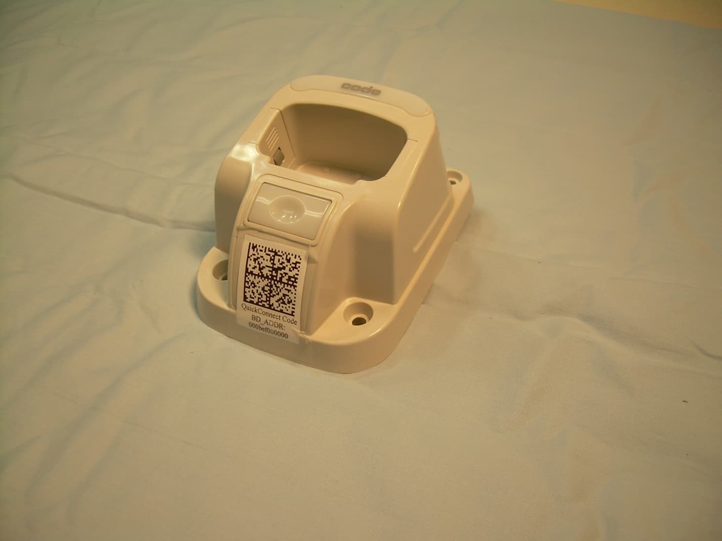
QQ6-BTC02
Dec 05, 2013CHARGER WITH BLUETOOTH TRANSCEIVER
Equipment Class
DSS - Part 15 Spread Spectrum Transmitter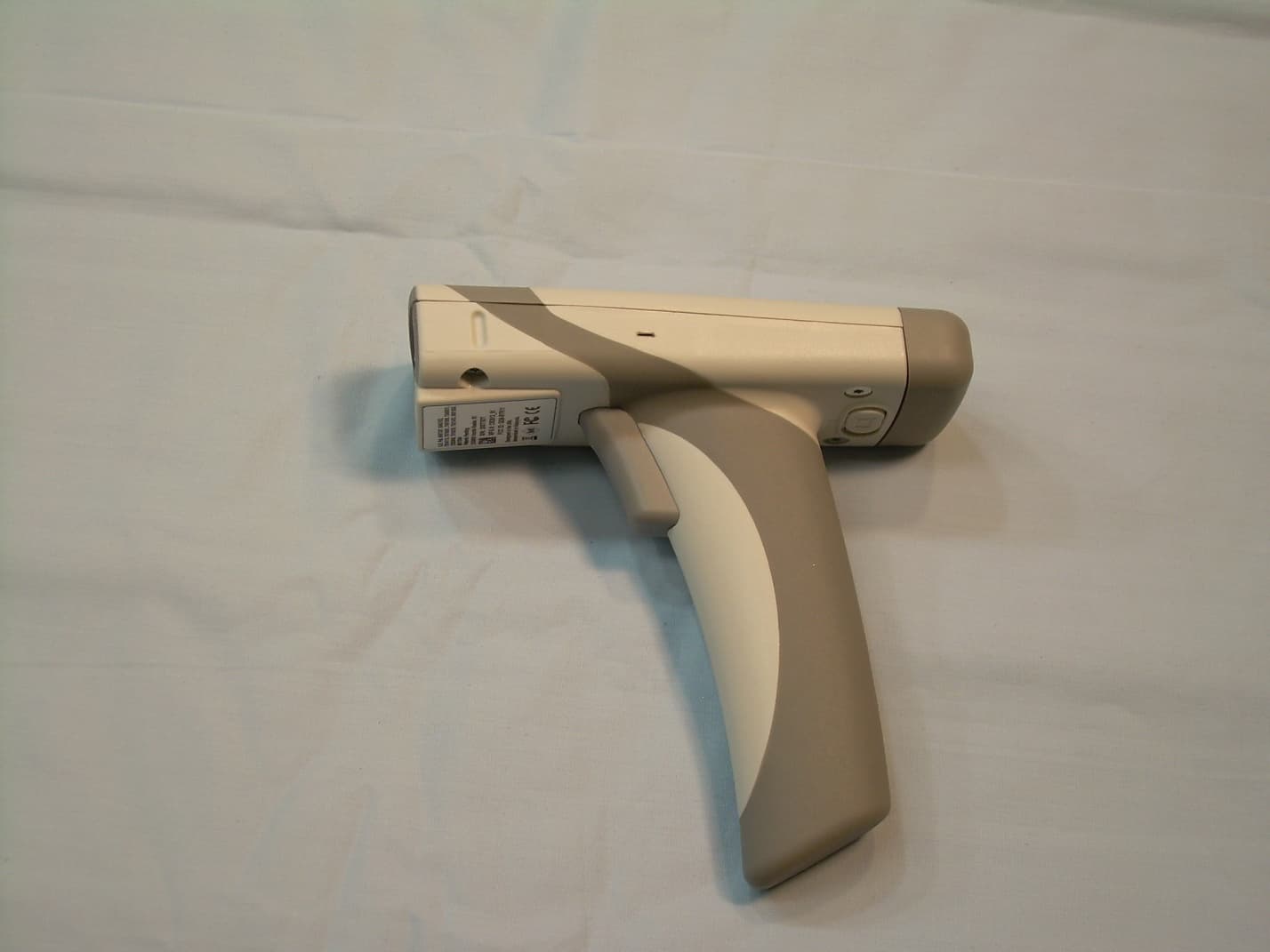
QQ6-BTR11
Feb 13, 2013BAR CODE READER
Equipment Class
DSS - Part 15 Spread Spectrum Transmitter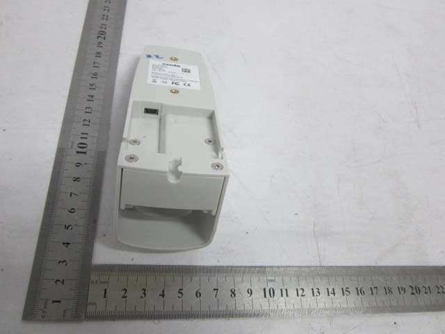
QQ6-RMS02
Apr 26, 2012ECS-RMS
Equipment Class
DSS - Part 15 Spread Spectrum Transmitter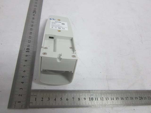
QQ6-RMS01
Feb 23, 2012ECS-RMS
Equipment Class
DSS - Part 15 Spread Spectrum Transmitter