QQE210AWireless Adapter Model: 210A
American TeleCare, Inc.
Click to zoom
Application Details
- Equipment Class
- DSS - Part 15 Spread Spectrum Transmitter
- Date of Grant
- Apr 03, 2003
- Application Purpose
- Original Equipment
- Date of Application
- Nov 21, 2002
- Equipment Note
- Wireless Adapter Model: 210A
- Frequency Range
- 2402.00000000 - 2480.00000000
- Company
- American TeleCare, Inc.
- Country
- United States
Documents & Files
Document Text
Text extracted from the exhibit documents filed with the FCC. Open a document above to read the original.
Users Manual
Wireless Adapter - Installation The Wireless Adapter can be attached to a medical device that has a data port, with the stereo audio plug connected to the device’s data jack. This replaces the cable which would otherwise connect between the medical device and the NX Patient Station, thus allowing the device to be locally mobile.
Users Manual
American TeleCare NX Monitoring Patient Station Installation and Operation Manual Revision 01 December 16, 2002 P206-001-OM ii Table of Contents Section 1 Introduction ....................................................................................... 1-1 Section 2 Phone Line Requirements in the Home............................................. 2-1 Section 3 NX Monitoring Network ................................................................... 3-1 1. Using Internet Access ............................................................................... 3-1 2. Using a Remote Access Dial In Service: .................................................. 3-2 Section 4 Installation of the NX Monitoring Station ........................................ 4-3 Section 5 Settings (Administrative) .................................................................. 5-1 A. Patient Settings......................................................................................... 5-1 B. Device Configuration ............................................................................... 5-3 To register a peripheral device containing a wireless adaptor module:... 5-4 C. Dialup Settings ......................................................................................... 5-5 D. Server Settings ......................................................................................... 5-6 Section 6 Uploading Data Outside of a Scheduled Monitoring Session........... 6-1 A. Obtaining Data from Devices using the Wireless Adaptor Module ........ 6-1 B. Entering Data into the Monitoring Station Manually .............................. 6-2 C. Using a Data Cable................................................................................... 6-3 Section 7 Completing a Scheduled Session ...................................................... 7-1 Section 8 Session List........................................................................................ 8-1 Section 9 Operating the Peripheral Devices...................................................... 9-2 A. Scale ......................................................................................................... 9-2 B. BP/Pulse Meter......................................................................................... 9-2 C. Glucose Meter .......................................................................................... 9-4 D. Pulse Oximeter ......................................................................................... 9-4 Section 10 Setting the Date and Time............................................................. 10-5 Section 11 Batteries ........................................................................................ 11-1 A. The Peripheral Medical Devices ............................................................ 11-1 B. The Wireless Adaptor Modules ............................................................. 11-1 Section 12 Care and Cleaning of the NX Monitoring Station ........................ 12-1 A. Appropriate Storage and Operation Temperatures ................................ 12-1 B. Cleaning the Monitoring Station ............................................................. 12-1 C. Maintenance and Calibration ................................................................. 12-1 Section 13 Returning Equipment for Repair................................................... 13-1 1-1 Section 1 Introduction The NX Monitoring Station allows a patient to obtain data from a variety of medical devices and send it directly to a server, without connecting with a health care provider. The patient can enter data into the Monitoring Station and send that data to a server at any time. The health care provider can also schedule monitoring sessions for each patient. In this case, the patient will be prompted to enter selected vital signs, answer specific questions and receive specific instructions from the health care provider at a date and time programmed into the Monitoring Station by the health care provider. The health care provider can access the vital sign data and the answers to the questions that are located on the server at any time. 2-1 Section 2 Phone Line Requirements in the Home The patients will require a POTS (Plain Old Telephone Service) line in their home. The Monitoring Station will not operate over anything but an analog phone line at this time. The unit also requires an RJ11 phone jack. 3-1 Section 3 NX Monitoring Network The following are two examples of configurations: 1. Using Internet Access Note that the positioning and configuration of the Firewall with regard to the NX Server and the internal Network may vary. One arrangement is shown below. Other arrangements are possible. Notes: 1. The NX Patient Station is configured with the local ISP telephone number, ISP login ID and ISP password so that it can connect to the Internet. It is also configured with the IP address to get to the Healthcare Organization. The IP address is that of the NX Server and must be external (i.e. visible at the Internet access point of the Router) and static. The Firewall restricts access to the NX Server to HTTPS encrypted connections with the specific IP address of the NX Server. The NX Server takes over from there further restricting access to connections with the proper ATI issued Certificates, followed by the requirement for a valid NX User ID and a valid NX User Password. 2. The connection between the NX Patient Station and the NX Server is an HTTPS connection and is encrypted using SSL. 3. The connection between the Healthcare Organization’s PC Workstation and the NX Server is an HTTPS connection and is encrypted using SSL. Router and Firewall NX Server NX Patient Station Healthcare Org. PC WorkStation Secure Data U pload Secure Data Transfer Healthcare Organization Network Pat. St. ISP Agency ISP 3-2 4. The NX Server uses the Apache Web Server. Any other web server software such as IIS must be disabled. 2. Using a Remo…
Text truncated - open the document above for the full version.
Block Diagram
International Certification Services, Inc. AMERICAN TELECARE, INC. WIRELESS ADAPTER MODEL: 210A BLOCK DIAGRAM BlueTooth System Chip RX TX
Cover Letter(s)
1100 Falcon Ave. Tele:320-864-4444 Glencoe, MN 55336 Fax: 320-864-6611 “Your Agent to Product Certifications and Licenses Throughout the World” To: Linda Elliott February 3, 2003 From: Duane R. Bagdons Correspondence Reference Number: 24484 731 confirmation Number: EA955974 I have just emailed into the file the following documents to satisfy this correspondence: User Manual The compliance statement is in section 14 of the above User Manual Regarding the User Manual, the customer is not going to have a specific manual just for the Wireless Adapter, they are going to use the NX Patient Station operations manual for both of these units. The wireless adapter is somewhat of a subset of the NX Patient Station in that it is the remote connection to the NX Patient Station. There are references in the manual to the Wireless Adapter. I have attached the manual for the NX Patient Station for your review. Thank you Duane INTERNATIONAL CERTIFICATION SERVICES INC.
Cover Letter(s)
1100 Falcon Ave. Tele:320-864-4444 Glencoe, MN 55336 Fax: 320-864-6611 “Your Agent to Product Certifications and Licenses Throughout the World” To: Diane Poole February 3, 2003 From: Duane R. Bagdons Correspondence Reference Number: 24641 731 confirmation Number: EA955974 I have just emailed into the file the following documents to satisfy this correspondence: Lower Band Edge Compliance graphs Parts List Tune Up Information User Manual (see note below) SAR (see note below) Regarding the User Manual, the customer is not going to have a specific manual just for the Wireless Adapter, they are going to use the NX Patient Station operations manual for both of these units. The wireless adapter is somewhat of a subset of the NX Patient Station in that it is the remote connection to the NX Patient Station. There are references in the manual to the Wireless Adapter. I have attached the manual for the NX Patient Station for your review. Regarding the SAR Report, this is for Specific Absorption Rate to Human Tissue in cases of cell phones and devices that are close proximity to human tissue. The Wireless Adapter is not in this category. It is mounted to the chassis of a medical input peripheral and acts as the wireless link between the NX Patient Station and the medical input peripheral. The closest the wireless adapter would ever get to Human tissue is approximately 4 feet. I do not believe the SAR testing is required for such a device. Thank you Duane INTERNATIONAL CERTIFICATION SERVICES INC.
Cover Letter(s)
American Telecare Model: Wireless Adapter FCC ID: QQE210A 731 Confirmation Number: EA955974 Band-edge (Lower) Compliance of RF Conducted Emissions International Certification Services, Inc. January 15, 2003 dBuV 30 40 50 60 70 80 90 100 Freq (Mhz) 2395 2396 2397 2398 2399 2400 2401 2402 2403 American TeleCare, Inc. Model: Wireless Adapter EUT in "TX DATA2" test mode (Single Frequency 2402 Mhz) BAND-EDGE COMPLIANCE OF RF CONDUCTED EMISSIONS 2400 Mhz Band Edge 2402 Mhz 96.7 dBuV 2399.568 Mhz 51.4 dBuV American TeleCare, Inc. Model: Wireless Adapter EUT in "TX DATA2" test mode (Spread Spectrum) BAND-EDGE COMPLIANCE OF RF CONDUCTED EMISSIONS 30 40 50 60 70 80 90 100 dBuV 2395 2396 2397 2398 2399 2400 2401 2402 2403 Freq (Mhz) 2402 Mhz 96.7 dBuV 2400 Mhz Band Edge 2399.6 Mhz 51.4 dBuV International Certification Services, Inc. January 15, 2003
Cover Letter(s)
1100 Falcon Ave. Tele:320-864-4444 Glencoe, MN 55336 Fax: 320-864-6611 “Your Agent to Product Certifications and Licenses Throughout the World” To: Diane Poole March 15, 2003 From: Duane R. Bagdons Subject: Response to Correspondence Ref No. 24948 1. The wireless adapter is simply a Bluetooth adapter that attaches (velcro) to a peripheral device (i.e. scale, pulse Oximeter, Glucose Meter or Blood Pressure Meter) and transmitts the data from the peripheral device to the NX Patient Station (American TeleCare FCC ID QQE206A). The wireless adapter attaches to the peripheral device and not to the patient connection. 2. Upper Bandedge Plot The Upper Bandedge Plot was already included in the test report that was submitted on Nov 22, 2002. The Transmittal had to be divided up into 2 sections (FCC report section A and FCC report section B) because of file size. The section of the report "Band-edge Compliance of RF Conducted Emissions" shows the plot of the upper band edge. Note: the only thing that was missing was the lower band edge plot. That was requested by you earlier and I sent that to you. Thank you Duane R. Bagdons INTERNATIONAL CERTIFICATION SERVICES INC. Patient Connection Peripheral Device Wireless Adapter module NX Patient Station
External Photos
1100 Falcon Ave. Tele:320-864-4444 Glencoe, MN 55336 Fax: 320-864-6611 “Your Agent to Product Certifications and Licenses Throughout the World” To: FCC November 2, 2002 From: Duane R. Bagdons AMERICAN TELECARE, INC. PRODUCT: WIRELESS ADAPTER MODEL 210A EXTERNAL PHOTOS INTERNATIONAL CERTIFICATION SERVICES INC. Wireless Adapter Module
ID Label/Location Info
This document contains confidential and proprietary information of American TeleCare, Inc. and cannot be used, duplicated, or disclosed without the express written permission of American TeleCare, Inc. American TeleCare, Inc. 7640 Golden Triangle Drive Eden Prairie, MN 55344 952-897-0000 www.americantelecare.com ANSI Y14.5-1994 TOLERANCES FCC Lables for Wireless Adapter TITLE PART NUMBER REVISION LEVEL REV 1A CXXX-XXXXX-MD DD MON YYYY DD MON YYYY JOHN BLOMBERG JOHN BLOMBERG ENGINEER DRAFTER APPROVED THIRD ANGLE PROJECTION NAMEDATE DATE NAME NAMEDATE SIZE C SCALE 8:1SHEET 1 OF 4 FRAC 1/X 1/XX ANG X X.X X.XX DEC .X .XX .XXX .XXXX TOL .1 .01 .005 .0005 ECO # DATE DESCRIPTION DWG DD MMM YYYY 0XXX XXXDES OF CHG REV XX APRV File Name: Labels for FCC testing Date: Monday, November 18, 2002 This document contains confidential and proprietary information of American TeleCare, Inc. and cannot be used, duplicated, or disclosed without the express written permission of American TeleCare, Inc. American TeleCare, Inc. 7640 Golden Triangle Drive Eden Prairie, MN 55344 952-897-0000 www.americantelecare.com ANSI Y14.5-1994 TOLERANCES FCC Lables for Wireless Adapter TITLE PART NUMBER REVISION LEVEL REV 1A CXXX-XXXXX-MD DD MON YYYY DD MON YYYY JOHN BLOMBERG JOHN BLOMBERG ENGINEER DRAFTER APPROVED THIRD ANGLE PROJECTION NAMEDATE DATE NAME NAMEDATE SIZE C SCALE 8:1SHEET 2 OF 4 FRAC 1/X 1/XX ANG X X.X X.XX DEC .X .XX .XXX .XXXX TOL .1 .01 .005 .0005 ECO # DATE DESCRIPTION DWG DD MMM YYYY 0XXX XXXDES OF CHG REV XX APRV File Name: Labels for FCC testing Date: Monday, November 18, 2002 This document contains confidential and proprietary information of American TeleCare, Inc. and cannot be used, duplicated, or disclosed without the express written permission of American TeleCare, Inc. American TeleCare, Inc. 7640 Golden Triangle Drive Eden Prairie, MN 55344 952-897-0000 www.americantelecare.com ANSI Y14.5-1994 TOLERANCES FCC Lables for Wireless Adapter TITLE PART NUMBER REVISION LEVEL REV 1A CXXX-XXXXX-MD DD MON YYYY DD MON YYYY JOHN BLOMBERG JOHN BLOMBERG ENGINEER DRAFTER APPROVED THIRD ANGLE PROJECTION NAMEDATE DATE NAME NAMEDATE SIZE C SCALE 8:1SHEET 3 OF 4 FRAC 1/X 1/XX ANG X X.X X.XX DEC .X .XX .XXX .XXXX TOL .1 .01 .005 .0005 ECO # DATE DESCRIPTION DWG DD MMM YYYY 0XXX XXXDES OF CHG REV XX APRV File Name: Labels for FCC testing Date: Monday, November 18, 2002 This document contains confidential and proprietary information of American TeleCare, Inc. and cannot be used, duplicated, or disclosed without the express written permission of American TeleCare, Inc. American TeleCare, Inc. 7640 Golden Triangle Drive Eden Prairie, MN 55344 952-897-0000 www.americantelecare.com ANSI Y14.5-1994 TOLERANCES FCC Lables for Wireless Adapter TITLE PART NUMBER REVISION LEVEL REV 1A CXXX-XXXXX-MD DD MON YYYY DD MON YYYY JOHN BLOMBERG JOHN BLOMBERG ENGINEER DRAFTER APPROVED THIRD ANGLE PROJECTION NAMEDATE DATE NAME NAMEDATE SIZE C SCALE 8:1SHEET 4 OF 4 FRAC 1/X 1/XX ANG X X.X X.XX DEC .X .XX .XXX .XXXX TOL .1 .01 .005 .0005 ECO # DATE DESCRIPTION DWG DD MMM YYYY 0XXX XXXDES OF CHG REV XX APRV File Name: Labels for FCC testing Date: Monday, November 18, 2002
Internal Photos
1100 Falcon Ave. Tele:320-864-4444 Glencoe, MN 55336 Fax: 320-864-6611 “Your Agent to Product Certifications and Licenses Throughout the World” To: FCC November 2, 2002 From: Duane R. Bagdons AMERICAN TELECARE, INC. PRODUCT: WIRELESS ADAPTER MODEL 210A INTERNAL PHOTOS PC BOARD (COMPONENT SIDE) INTERNATIONAL CERTIFICATION SERVICES INC. Internal BlueTooth Antenna International Certification Services, Inc. [email protected] INTERNAL PHOTOS PC BOARD (SOLDER SIDE)
Operational Description
Wireless Adapter - Description The Wireless Adapter is a small device that converts an RS232 signal fed into its stereo audio cable to the Bluetooth wireless standard. It can communicate with the Bluetooth wireless interface circuit inside the NX Patient Station. The NX Patient Station can record vital signs (e.g. blood pressure, pulse, weight, blood sugar, oxygen saturation) from medical device peripherals that are connected to it, either by cable or wireless. The Wireless Adapter can be attached to a medical device that has a data port, with the stereo audio plug connected to the device’s data jack. This replaces the cable which would otherwise connect between the medical device and the NX Patient Station, thus allowing the device to be locally mobile.
Parts List/Tune Up Info
American TeleCare, Inc. Model: Wireless Adapter 210 Active Standby Ref Des Icc (mA) Icc (uA) 1 U1 Single Chip Bluetooth System CSR BC212015BDN BGA96 (.65mm) 10.00 10.00 1 U2 8 Mbit Flash Memory SST SST39VF800-90-4C-B3K BGA48 (.8mm) 2.35 2.35 1 U3 Bluetooth Chip Antenna Centurion CAF95901 2-Pin 0.00 1 U4 2.4GHz Bandpass Filter Soshin MDR741F 4-Pin 0.00 1 T1 Bluetooth Balun TDK HHM1517 2012 0.50 0.50 4 L1,L2,L3,L5 3.9nH Inductor Murata LQP15MN3N9B00 0402 0.10 0.40 1 X1 16MHz Crystal Toyocom TSX-10A@16MHZ 4x2.5mm 5.00 5.00 1 U7 PIC Microcontroller Microchip PIC12C509A-04/SN SOIC8 1 1 1.00 1.00 1 U6 RS-232 Receiver Maxim MAX3181EEUK-T SOT23-5 1 0.69 0.69 1 U5 Single Gate Logic Buffer Fairchild NC7SZ125P5X SC70-5 6 0.20 0.20 2 U8,U9 Voltage Regulator Linear Tech LT1615ES5-1 SOT23-5 10 40 1.65 3.30 1 U10 Single Gate Inverter Fairchild NC7SP14P5X SC70-5 0.75 0.75 1 L4 4.7uH Boost Inductor Murata LQH32CN4R7M11B L1210 0.10 0.10 2 D1,D3 Schottky Diode On MBR0520LT1 SOD-123 0.12 0.24 1 D2 Transient Voltage Suppressor Littlefuse V5.5MLA0603H 0603 0.50 0.50 1 L6 22 uH Boost Inductor Murata LQH32CN220K21 L1210 0.10 0.10 2 C1,C4 10uF Cap C0805 0.05 0.10 2 C2,C6 4.7uF Cap C0805 0.05 0.10 1 C19 100nF Cap C0603 0.05 0.05 2 C13,C14 10nF Cap C0402 0.05 0.10 1 C17 220pF Cap C0402 0.05 0.05 3 C10,C11,C20 47pF Cap C0402 0.05 0.15 1 C12 15pF Cap C0402 0.05 0.05 1 C15 10pF Cap C0402 0.05 0.05 2 C3,C5 4.7pF Cap C0402 0.05 0.10 1 C16 3.3pF Cap C0402 0.05 0.05 2 C8,C9 1.8pF Cap C0402 0.05 0.10 1 R2 2.15M Res 0603 0.01 0.01 2 R1,R8 1M Res 0402 0.01 0.02 1 R7 604K Res 0402 0.01 0.01 1 R5 182K Res 0402 0.01 0.01 1 R4 1K Res 0402 0.01 0.01 Bluetooth Module Bill of Materials Quantity Description Manufacturer Mfr. Part # Package Unit Cost Cost 15 47 1 of 2 American TeleCare, Inc. Model: Wireless Adapter 210 1 R3 2.2 Ohm Res 0402 0.01 0.01 1 P3 Development Connector Molex 53398-0690 6-Pin 1.00 1.00 TOTALS 26 95 26.10 2 of 2
Schematics
1 4234 5 2 1 4 3 5 2
Test Report
TEST REPORT #021002A STANDARD: FCC PART 15 SUBPART C--INTENTIONAL RADIATORS SECTION 15.247 OPERATION IN THE BANDS 902-928 Mhz, 2400-2483.5 Mhz, and 5725-5850 Mhz EQUIPMENT TESTED: AMERICAN TELECARE, INC. MODEL: WIRELESS ADAPTER 210A TEST DATE: 02 OCTOBER 2002 INTERNATIONAL CERTIFICATION SERVICES, INC. 1100 Falcon Avenue Glencoe, MN 55336 Tele: 320-864-4444 Fax: 320-864-6611 INTERNATIONAL CERTIFICATION SERVICES, INC. Prepared for: Test agent: Test location: Prepared by: . American TeleCare, Inc. 7640 Golden Triangle Drive Eden Prairie, MN 55344 International Certification Services, Inc. 1100 Falcon Avenue Glencoe, MN 55336 Tele: 320-864-4444 Fax: 320-864-6611 International Certification Services, Inc. 1100 Falcon Avenue Glencoe, MN 55336 Tele: 320-864-4444 Fax: 320-864-6611 International Certification Services, Inc. 1100 Falcon Avenue Glencoe, MN 55336 International Certification Services represents to the client that testing is done in accordance with standard procedures applicable and that reported test results are accurate within generally accepted commercial ranges of accuracy. This report only applies to the specific samples tested under stated test conditions. It is the manufacturer’s responsibility to assure that additional production units of this model are manufactured with identical electrical and mechanical components. International Certification Services shall have no liability for any deductions, inferences or generalizations drawn by the client or others from this report. This report is the confidential property of the client. As a mutual protection to our clients, the public and ourselves, extracts from the test report shall not be reproduced except in full without our written approval. INTERNATIONAL CERTIFICATION SERVICES, INC. 1.0 TEST SUMMARY TEST REPORT: #021002A COMPANY: AGENT: International Certification Services, Inc. PHONE: 320-864-4444 TEST DATE: EQUIPMENT UNDER TEST: GENERAL TEST SUMMARY: VERIFICATION / CERTIFICATION STATUS: MODIFICATIONS NECESSARY: TESTED BY WRITTEN BY Steve Wendlandt Duane R. Bagdons American TeleCare, Inc. 02 October, 2002 Wireless Adapter Model: 210A The testing was performed at International Certification Services, Inc. at 1100 Falcon Ave, Glencoe, MN 55336 The American TeleCare, Inc. Model: Wireless Adapter 210A system was found to be in compliance with the FCC Part 15 Subpart C, Section 15.247 requirements. None INTERNATIONAL CERTIFICATION SERVICES, INC. Applicable Standards 47 CFR Ch.1 (10-1-98 Edition) FCC Part 15 Radio Frequency Devices Subpart C Intentional Radiators Section 15.247 Operation in the Bands 902-928 Mhz, 2400-2483.5 Mhz, 5725-5850 Mhz 2.1 Referenced Standards ANSI C63.4-1992 Methods of Measurement of Radio-Noise Emissions from Low- Voltage Electrical and Electronic Equipment in the Range of 9 Khz to 40 Ghz. 2.2 Equipment Units Tested The equipment tested is a small device that converts an RS232 signal fed into its stereo audio cable to the Bluetooth wireless standard. It can communicate with the Bluetooth Wireless Interface circuit inside the American TeleCare, Inc. NX Patient Station. The NX Patient Station can record vital signs (e.g. blood pressure, pulse, weight, blood sugar, oxygen saturation) from medical device peripherals that are connected to it, either by cable or wireless. The Wireless Adapter can be attached to a medical device that has a data port, with a stereo audio plug connected to the device’s data jack. This replaces the cable which would otherwise connect between the medical device and the NX Patient Station, thus allowing the device to be locally mobile. The incorporated Spread Spectrum (Blue Tooth) wireless transmitter communicates between the peripheral health measuring devices and the computer to record the measured data. The Spread Spectrum signal generation and transmission is performed by a chip made by CSR, Ltd (BlueCore 2 External single chip Blue Tooth System P/N: BC212013). All hardware functions are generated in this chip for the RF signals. The antenna is a BlueChip by Centurion Wireless Technologies, Inc. This component is ¼ wave antenna self contained in a miniature chip package. All RF and spread spectrum controls are hardware and software with no adjustments left to the operator. The Spread Spectrum output transmits on 79 frequencies with a dwell time at each frequency of 420 uS and a carrier frequency separation of 1.006 Mhz. The exact measured data is given in subsequent sections of this report. The receiver is a SAW based type device and do not have a local oscillator. This part of the system has been verified here at the lab also for radiated emissions and found to be compliant with the 15.109 regulation for Radiated Emission Limits. 2.3 Equipment and Cable Configuration See photos of the EUT PC board and schematic and test configuration setup in additional attachments associated with this report filing. INTERNATIONAL CERTIFICATION SERVICES, INC. 2.4 List of Test Equipment Measurement cable losses, and antenna correction factors are included in the Corrected Data column of the data sheet. Quasi Peak Detection was used for measuring the Fundamental frequency signal and Average detection method was used to measure the Harmonics since they were all above 1000 Mhz. The Resolution BW was set at 100 Khz and the Video BW was set at 1 Hz with a Span of 0 Hz to perform the correct average detected measurements. All measurements were taken using the “Measurement Guidelines for Frequency Hopping Spread Spectrum Systems” (FCC DA 00-705 released March 20, 2000). Most measurements were taken with the Spectrum Analyzer directly connected to the EUT Transmitter as required by the above mentioned FCC Guidelines document. Only the Radiated Spurious Harmonics was measured on the OATS site. 2.5 Units of Measurement. All OATS measurements were taken in dBuV/m with the antenna located at 1 meter distance from the EUT. Frequency measurements are recorded in Mhz. 2.6 Location of Test Site The open area test…
Text truncated - open the document above for the full version.
Test Report
Spurious RF Radiated Emissions As required by the FCC guidelines for testing this device, two plots are drawn on each graph. The first one is with the Video Bandwidth set at 3 times the Resolution Bandwidth (i.e. RBW = 1 Mhz, VBW = 3 Mhz) with the Peak Detector ON and the second plot is with the Video Bandwidth changed to VBW = 10 Hz to effect an AVERAGE detection of the signal. Also, since the dwell time per channel was less than 100 mS, the reading obtained with the 10 Hz VBW was adjusted by a “duty cycle correction factor” derived from 20 LOG (Dwell time/100 mS), in an effort to demonstrate compliance with the 15.209 limit. International Certification Services, Inc. October 8, 2002 RBW = 1 Mhz, VBW = 3 Mhz RBW = 1 Mhz, VBW = 10 Hz 15.209 Limit American TeleCare, Inc. Model: Wireless Adapter Radiated Spurious Emissions in Restricted Bands (15.205) (2483.5 to 2500 Mhz) dBuV -40 -20 0 20 40 60 Freq (Mhz) 2483248824932498 INTERNATIONAL CERTIFICATION SERVICES, INC. Spurious RF Radiated Emissions International Certification Services, Inc. October 8, 2002 RBW = 1 Mhz, VBW = 3 Mhz RBW = 1 Mhz, VBW = 10 Hz 15.209 Limit dBuV -40 -20 0 20 40 60 Freq (Mhz) 265027002750280028502900 American TeleCare, Inc. Model: Wireless Adapter Radiated Spurious Emissions in Restricted Bands (15.205) (2655 to 2900 Mhz) INTERNATIONAL CERTIFICATION SERVICES, INC. Spurious RF Radiated Emissions October 8, 2002 International Certification Services, Inc. RBW = 1 Mhz, VBW = 3 Mhz RBW = 1 Mhz, VBW = 10 Hz 15.209 Limit dBuV -20 -10 0 10 20 30 40 50 60 Freq (Mhz) 32603261326232633264326532663267 American TeleCare, Inc. Model: Wireless Adapter Radiated Spurious Emissions in Restricted Bands (15.205) (3260 to 3267 Mhz) INTERNATIONAL CERTIFICATION SERVICES, INC. Spurious RF Radiated Emissions International Certification Services, Inc. October 8, 2002 RBW = 1 Mhz, VBW = 3 Mhz RBW = 1 Mhz, VBW = 10 Hz 15.209 Limit dBuV -20 -10 0 10 20 30 40 50 60 Freq (Mhz) 33323333333433353336333733383339 American TeleCare, Inc. Model: Wireless Adapter Radiated Spurious Emissions in Restricted Bands (15.205) (3332 to 3339 Mhz) INTERNATIONAL CERTIFICATION SERVICES, INC. Spurious RF Radiated Emissions International Certification Services, Inc. October 8, 2002 15.209 Limit dBuV -20 -10 0 10 20 30 40 50 60 Freq (Mhz) 3345334733493351335333553357 American TeleCare, Inc. Model: Wireless Adapter Radiated Spurious Emissions in Restricted Bands (15.205) (3345.8 to 3358 Mhz) RBW = 1 Mhz, VBW = 3 Mhz RBW = 1 Mhz, VBW = 10 Hz INTERNATIONAL CERTIFICATION SERVICES, INC. Spurious RF Radiated Emissions International Certification Services, Inc.October 8, 2002 RBW = 1 Mhz, VBW = 3 Mhz RBW = 1 Mhz, VBW = 10 Hz 15.209 Limit dBuV -20 -10 0 10 20 30 40 50 60 Freq (Mhz) 360037003800390040004100420043004400 American TeleCare, Inc. Model: Wireless Adapter Radiated Spurious Emissions in Restricted Bands (15.205) (3600 to 4400 Mhz) INTERNATIONAL CERTIFICATION SERVICES, INC. Spurious RF Radiated Emissions International Certification Services, Inc. October 8, 2002 RBW = 1 Mhz, VBW = 3 Mhz RBW = 1 Mhz, VBW = 10 Hz 15.209 Limit dBuV 0 10 20 30 40 50 60 Freq (Mhz) 4500460047004800490050005100 American TeleCare, Inc. Model: Wireless Adapter Radiated Spurious Emissions in Restricted Bands (15.205) (4500 to 5150 Mhz) INTERNATIONAL CERTIFICATION SERVICES, INC. Spurious RF Radiated Emissions International Certification Services, Inc. October 8, 2002 RBW = 1 Mhz, VBW = 3 Mhz RBW = 1 Mhz, VBW = 10 Hz 15.209 Limit dBuV 0 10 20 30 40 50 60 Freq (Mhz) 535053705390541054305450 American TeleCare, Inc. Model: Wireless Adapter Radiated Spurious Emissions in Restricted Bands (15.205) (5350 to 5460 Mhz) INTERNATIONAL CERTIFICATION SERVICES, INC. Spurious RF Radiated Emissions International Certification Services, Inc.October 8, 2002 RBW = 1 Mhz, VBW = 3 Mhz 15.209 Limit dBuV 0 10 20 30 40 50 60 Freq (Mhz) 725073507450755076507750 American TeleCare, Inc. Model: Wireless Adapter Radiated Spurious Emissions in Restricted Bands (15.205) (7250 to 7750 Mhz) RBW = 1 Mhz, VBW = 3 Mhz INTERNATIONAL CERTIFICATION SERVICES, INC. Spurious RF Radiated Emissions International Certification Services, Inc. October 8, 2002 RBW = 1 Mhz, VBW = 3 Mhz RBW = 1 Mhz, VBW = 10 Hz 15.209 Limit dBuV 0 10 20 30 40 50 60 Freq (Mhz) 80258125822583258425 American TeleCare, Inc. Model: Wireless Adapter Radiated Spurious Emissions in Restricted Bands (15.205) (8025 to 8500 Mhz) INTERNATIONAL CERTIFICATION SERVICES, INC. Spurious RF Radiated Emissions International Certification Services, Inc. October 8, 2002 RBW = 1 Mhz, VBW = 3 Mhz RBW = 1 Mhz, VBW = 10 Hz 15.209 Limit dBuV 0 10 20 30 40 50 60 Freq (Mhz) 90009050910091509200 American TeleCare, Inc. Model: Wireless Adapter Radiated Spurious Emissions in Restricted Bands (15.205) (9000 to 9200 Mhz) INTERNATIONAL CERTIFICATION SERVICES, INC. Spurious RF Radiated Emissions International Certification Services, Inc. October 8, 2002 RBW = 1 Mhz, VBW = 3 Mhz RBW = 1 Mhz, VBW = 10 Hz 15.209 Limit dBuV 0 10 20 30 40 50 60 Freq (Mhz) 93009350940094509500 American TeleCare, Inc. Model: Wireless Adapter Radiated Spurious Emissions in Restricted Bands (15.205) (9300 to 9500 Mhz) INTERNATIONAL CERTIFICATION SERVICES, INC. Spurious RF Radiated Emissions International Certification Services, Inc. October 8, 2002 RBW = 1 Mhz, VBW = 3 Mhz RBW = 1 Mhz, VBW = 10 Hz 15.209 Limit Freq (Mhz) 1060011100116001210012600 dBuV 0 10 20 30 40 50 60 American TeleCare, Inc. Model: Wireless Adapter Radiated Spurious Emissions in Restricted Bands (15.205) (10600 to 12700 Mhz) INTERNATIONAL CERTIFICATION SERVICES, INC. Spurious RF Radiated Emissions International Certification Services, Inc. October 8, 2002 RBW = 1 Mhz, VBW = 3 Mhz RBW = 1 Mhz, VBW = 10 Hz 15.209 Limit dBuV 0 10 20 30 40 50 60 Freq (Mhz) 13250133001335013400 American TeleCare, Inc. Model: Wireless Adapter Radiated Spurious Emissions in Restricted Bands (15.205) (13250 to 13400 Mhz) INTERNATIONAL CERTIFICATION SERVICES, INC. Spurious RF R…
Text truncated - open the document above for the full version.
Test Setup Photos
1100 Falcon Ave. Tele:320-864-4444 Glencoe, MN 55336 Fax: 320-864-6611 “Your Agent to Product Certifications and Licenses Throughout the World” To: FCC November 4, 2002 From: Duane R. Bagdons American TeleCare, Inc. Wireless Adapter Model: 210A Test Configuration Intentional Radi…
Text truncated - open the document above for the full version.
Contact Information
Applicant
Rich Abbruscato(Chief Technology Officer)
Test Firm
International Certification Services Inc.Duane Bagdons
Technical Specifications
| # | Rule Parts | Frequency Range | Power Output |
|---|---|---|---|
| 1 | 15C | 2.40 GHz - 2.48 GHz | 110.00 mW |
Other Applications from American TeleCare, Inc.
QQE206A
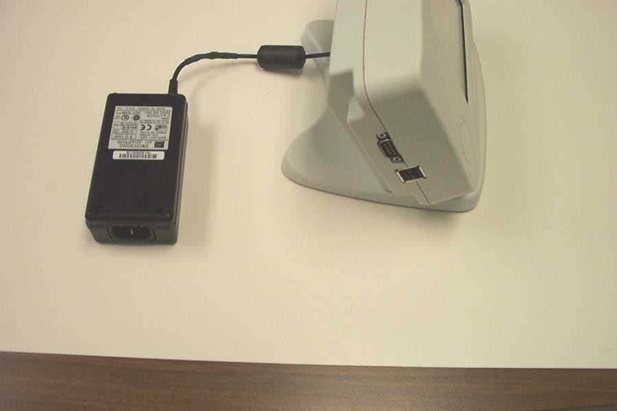
Feb 25, 2003NX Patient Station Model: 206A
Equipment Class
DSS - Part 15 Spread Spectrum Transmitter