QQH-AIR-X1000B2 Way Car Alarm System
SEMIkorea Co., Ltd.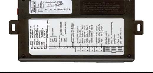
Click to zoom
Application Details
- Equipment Class
- DSR - Part 15 Remote Control/Security Device Transceiver
- Date of Grant
- Dec 01, 2002
- Application Purpose
- Original Equipment
- Date of Application
- Dec 01, 2002
- Equipment Note
- 2 Way Car Alarm System
- Frequency Range
- 447.67500000 - 447.67500000
- Company
- SEMIkorea Co., Ltd.
- Country
- South Korea
Documents & Files
Document Text
Text extracted from the exhibit documents filed with the FCC. Open a document above to read the original.
Users Manual
Contents Before using the system 1. How to use the DIP switch 2. Product wiring diagram 3. 6 Pin main wire(CON1) 4. Signal Output Connector(CON 2) 5. Door Control Output Connector(CON 3) 6. Valet Switch Module Ass’y(CON4) 7. LED Module Assiy(CON5) 8. Shock sensor(CON6) 9. Trigger Input Connector(CON 7) 10. Using relay 11. Registering the remote control ID 12. Configuring time data 13. Configuration summary table 14. Antenna location Thank you for choosing AIRWOLF, a remote engine starter system manufactured by Semi Korea Inc. You are about to experience the convenience and the various carefully designed functions for customer satisfaction. To fully benefit from the capabilities of your AIRWOLF system, we encourage you to read this user manual thoroughly before using the system. ※ Caution 1. Read this manual carefully and ensure safety before you install the equipment. 2. Make sure to install the equipment by an authorized dealer. 3. In order to prevent safety accidents, users shall be attentive of the following precautions: - In the manual mode, do not attempt remote start as the gear is being applied. - Do not attempt remote start as the key is being inserted (that is, while the ignition is on). - Do not attempt remote start when the car is shut in or in poor ventilated location. - Do not attempt remote start when there is someone or a pet inside the car. - Do not attempt remote start when there is someone standing in front of or rear of the car. - Always apply the parking brake, and put your car in neutral or P (park) gear. 4. Stop operating the equipment if the gear is applied, or the equipment malfunctions, to prevent loss of lives and property. 5. Please contact the dealer for other problems. 5 7 8 10 14 18 18 18 19 25 27 28 32 32 TThhiiss ddeevviiccee ccoommpplliieess wwiitthh ppaarrtt 1155 ooff tthhee FFCCCC RRuulleess.. OOppeerraattiioonn iiss ssuubbjjeecctt ttoo tthhee ffoolllloowwiinngg ttwwoo ccoonnddiittiioonnss:: (1) This device may not䜋cause harmful interference, and (2) this device must accept any interference received, including interference that may䜋cause undesired operation. ccaauuttiioonn:: Any changes or modifications in construction of this device which are not expressly approved by the party responsible for compliance could void the user's authority to operate the equipment. 4 Precautions for installation 1. How to use the DIP switch 5 - Air wolf operates in DC 12V in either automatic or manual car. - Before you install the equipment, check the polarity of power door lock and power trunk release button. - Use the multimeter rather than the test lamp, if possible. Overcurrent on the test lamp may cause damage to the computer system of the car. - Switch off the dome light before installing the equipment. If you leave the car with the doors left open, the battery may be discharged. - Solder the wires and apply the insulation tape. - Fix the ground wire of Brain to the rarely used bolt. - In preparation for unexpected discharge of battery, remove the dome light fuse while installing the equipment. - When installing siren or TACH sensor, be careful not to have the wire uncovered by the chassis of the car. - Do not place the wires or parts on the hot place or moving part of the car. - Make sure to place the Auto/Manual selection switch “ON”for the manual car. The installer is responsible for any damage caused by mishandling of the switch. Alternator/Tach Alternator/Tach 3 ● Switch 1 :Used for selection of TACH / Alternator. ● Switch 2 :Used for selection of Manual/Automatic. Place the switch On for manual, or Off for automatic. ※※PPrreeccaauuttiioonn :: TThhee iinnssttaalllleerr iiss ffuullllyy rreessppoonnssiibbllee ffoorr aannyy aacccciiddeenntt ccaauusseedd bbyy mmiisshhaannddlliinngg ooff tthhee sswwiittcchh.. ● Switch 3 :Used for setting of TACH learning. DIP S/W OFF TACHAutomatic Normal Alternator Manual ON 1 2 Install 3 7 6 2. Product wiring diagram A. With starter A. With starter 9 8 B. Without starter Please refer to ‘wiring diagram of with starter chart’when you add ‘starter module’for option. 11 3. 6-pin main wire (CON1) 10 ①①RReedd ((䥳䥳1122VV))::䥳䥳1122VV mmaaiinn ppoowweerr iinnppuutt Brain receives 䥳12V from the car battery as the main power supply. ②②ppuurrppllee((ssttaarrtt))::䥳䥳oouuttppuutt ffoorr ssttaarrtt mmoottoorr The 䥳12V output is used for start motor. Turn the key, find the wire that becomes 䥳12V when the start motor starts running, and connect the wire to the violet. The output keeps 1~3V once the engine is started. ③③YYeellllooww(( IIGG 11))::IIGGNN 11 䥳䥳oouuttppuutt The 䥳12V output is used to start the engine. Find the wire that becomes 䥳12V when the key is in the “ON”position or when the start motor turns, and after the engine is started. And connect the wire to the yellow wire. ④④OOrraannggee((IIGG 22))::IIGGNN 22 䥳䥳oouuttppuutt The 䥳 output is used to start the supplementary devices such as heater and air conditioner which are not related to the engine.Find the wire that becomes 䥳12V when the key is in the “ON”position or when the engine is started. The output keeps 1~3V while the start motor turns. ⑤⑤BBllaacckk((GGNNDD))::CCoonnnneecctt tthhee wwiirree ttoo tthhee cchhaassssiiss.. ((GGrroouunndd IInnppuutt)) ⑥⑥BBlluuee//BBllaacckk:: AAuuxxiilliiaarryy IIGGNN 11䥴䥴oouuttppuutt A reserved IG 1 output (-300MA) for cars of two IG 1s. In this case, an external relay is required. It works in the same ways as IG 1. ⊙⊙66PP MMaaiinn WWiirree((wwiirriinngg ddiiaaggrraamm)) ①① ②② ③③ ④④ ⑤⑤ ⑥⑥ Red purple Yellow Orange Black Blue/Black 䥳12V main power input 䥳 output for start motor IGN 1 䥳 output IGN 2 䥳 output Ground Input Auxiliary IGN 1䥴output ①① ②② ③③ ④④ ⑤⑤ ⑥⑥ SSttaarrtteerr oonnllyy 12 13 4. Signal Output Connector(CON 2 ) ③③wwhhiittee//BBllaacckk:: GGNNDD((GGrroouunndd ttoo tthhee VVeecchhiiccllee bbooddyy)) UUsseedd ffoorr wwiitthhoouutt ssttaarrtteerr oonnllyy Connect the wire to the chassis ground. ④④GGrraayy:: TTrruunnkk RReelleeaassee oouuttppuu…
Text truncated - open the document above for the full version.
External Photos
(External Photos)
Internal Photos
(Internal Photos)
Operational Description
Air-X1000 designed to report the real time status of your car whenever you want and
Schematics
5 5 4 4 3 3 2 2 1 1 DD CC BB AA DATA_IN 5V DATA OUT RX/BS RSSI P B/S TX B/S GND Air-X1000 (BRAIN_RF BOARD) CIRCUIT SEMI KOREA , Ltd. * * * * * * * * * * * * * * PCB DATE 2002.5.30 A Air-X1000 BRAIN _RF A3 11Monday, September 23, 2002 Title SizeDocument NumberRev Date:Sheet of TP1 TP2 Vreg(+1.0V) Vreg(+1.0V) Vreg(+1.0V) TP3 VCC_3V VCC_3V + TC5 47uF C104 104 C103 104 + TC4 N.C CON2 SINGLE 1 2 R98 51k R99 N.C Q13 KTA1505S R681K R65 1K R69 000 Q12 KTA1505S U2 ANT2 1 In R55 1k C38 1p R75 68k C37 5p IC1TA31145 12345678910 11121314151617181920 OSC IOSC OMIX OVCCIF IDECFSK RQUADAF OUTRSSI LPF I LPF O B/S CHARGE FSK O ALM REG CREG O GNDMIX I R1 390K L1 8.2N C79 103 C1 0.5p LTUCG455G F2 21 3 C3 220p C2 5p R76 56k R6 000 C94 0.5p R2 33K R94 18k C99 100p D1 MMBV3401 L93 18nH L2 27N C74 104 Q1 4228(R45) C4 10p R90 51k R93 0 C71 104 Q2 4226(R25)R3 15K X3 (447.675-21.4)/9 L31 1.2uH R31 22k CON1 SINGLE 1 2 3 4 5 6 7 8 1 2 3 4 5 6 7 8 Q6 KTA1505 C7 7p L3 12N C57 102 C31 5p R97 15k R5 15k VC1 20p C6 N.C X2 JTBC455C32 R72 3.3k C8 220p + TC1 10uF C53 15p C100 10p C92 2p L92 22nH C52 102 C75 104 R4 30 +TC3 10uF C9 N.C Q5 4226(R25) R95 N.C C10 N.C L71 3.3uH Q8 4226(R25) C32 10p C54 15p C13 7p L4 12N C11 1p C101 8p Q3 4228(R45) C12 5p C33 22p L91 27nH L32 1.2uH R96 91 R51 22k L51 3.3uH L52 3.3uH C80 102 C81 104 R52 2.2k R73 68k C51 N.C IC2 TDA5100 1 2 3 4 5 6 7 8 9 10 11 13 14 15 16 12 PDWN LTD VS LF GND ASKDTA FSKDTA CLKOUT CLKDIVCOSC FSKOUT PAGND PAOUT FSEL CSEL FSKGND C96 N.C C78 560p C77 102 R53 100 C76 3300p IC3S-818A30AMC-BKG-T2 1 2 34 5 Vin vsson/offnc Vout C34 220p L33 10nH R32 43k C97 102 R34 30 C93 2p C98 0.5p R33 2.2k VC2 2.5p X4 447.675MHz/32 X1 20.945MHz C39 102 C73 27p C91 2p C72 33p L90 100nH C35 2p C36 2p C95 100p D2 MMBV3401 R74 68k R91 4.7k R71 22k L34 15nH C90 104 R92 10k 21.4M F1 1 2 3 + TC2 1uF R54 51k Q4 KTC3880Y C55 102 C56 102 GND ANT A A B B C C D D 55 44 33 22 11 12V IGN1 IGN2 START GND MUSSO (LPG) IGN1 IGN2 START REARM DISARM AUX1/SK AL/GEN AUX2/DI AUX3/DO LOCK UNLOCK IGN2 DATA-IN START IGN1 P/L ST-KILL TRUNK KEY-SEN HOOD TRUNK DOOR BRAKE DOME SIREN GLOW LED/CS R/TX-BS DOME-Lt DATA-OUT SHOCK-L SHOCK-H (VALET) SLECT DISARM AUX1 REARM AUX2 AUX3 HOOD BRAKE VALET P/L In TRUNK GLOW- DOME-Lt DOOR- LED DOOR+ TX-BS SIREN GLOW+ START KILL TRUNK P/L+ (C3265) (C3265) (C3265) (A1298) (Gas/Mussoo) Pwr BS SHOCK-H SHOCK-L Tach/Gen Auto/Manual R46~52 10K x 7 R53~59 10K x 7 Air-X1000 (BRAIN_LOGIC BOARD) CIRCUIT RF MODULE R/TX-BS DATA out DATA in (A1298) UNLOCK (A1298) LOCK GND Alternator/TACH Select Install Auto/Manual Select PCB DATE 2002 . 10 . 10W-C Air-X1000 BRAIN_LOGIC A3 11Monday, October 21, 2002 Title SizeDocument NumberRev Date:Sheetof 12V 3.3V 3.3V 3.3V 3.3V 3.3V 3.3V 3.3V 3.3V 12V 12V 3.3V 3.3V 3.3V 3.3V 3.3V12V R20 10K Q3 KTN2222AS D20 LL4148 R19 10K CON5 2 HEADER 1 2 CON7 HEADER 10 1 2 3 4 5 6 7 8 9 10 ZD4 3V 0.5W R29 220K R24 10K RY2 RELAY DPST 43 65 1 2 R22 10K R30 220K EC2 470uF/10V CON6 HEADER 4 1 2 3 4 C4 104 C13 104 R21 10K C9 15P EC1 470uF/25V ZD2 27V 1W CON8 2 HEADER 12 D241N4004 ZD1 27V 1W Q6 KRC109S D271N4004 R33 2.2K R37 100K D1 1N4004 R3 10K R40 2.2K Q1 KTN2907AS D18LL4148 T1 ANT Q7 A1276 ZD5 3V 0.5W R4 1K D261N4004 R38 15K R36 10K Q2 KTN2907AS D21 1N4004 RY1 RELAY DPST 43 65 1 2 D5 1N4004 R34 4.7K R5 10K ZD63V 0.5W C2 104 R1 10K D19LL4148 D2 1N4004 R39 10K D3 1N4004 D231N4004 U3 KID65003AF 1 2 3 4 5 6 7 89 10 11 12 13 14 15 16 IN IN IN IN IN IN IN GNDCOM OUT OUT OUT OUT OUT OUT OUT R2 1K R25 100K R15 560K CON3 HEADER 4 1 2 3 4 D251N4004 C1 104 CON2 HEADER 12 1 2 3 4 5 6 7 8 9 10 11 12 CON1 6 HEADER 1 2 3 4 5 6 Q4 KTN2222AS Q9 KTN2907AS R6 56K ZD73V 0.5W RY3 RELAY DPST 43 65 1 2 R7 100K TNR1 INR7D220K D4 1N4004 U5 AT93C46 8 7 6 54 3 2 1 VDD NC PRDT GNDDO DI SK CS C12 684 ZD3 27V 1W D14 UF4004 Q10 KTN2222AS R62 100K RY6 Trunk 3 5 4 1 2 R63 300K C10 15P C3 104 74HC241 U4 3 5 7 9 12 14 16 18 17 15 13 11 8 6 4 2 20 19 1 2Y4 2Y3 2Y2 2Y1 1Y4 1Y3 1Y2 1Y1 2A4 2A3 2A2 2A1 1A4 1A3 1A2 1A1 VCC 2OE 1OE C6 224 R13 1M R41 10K CON4 2 HEADER 1 2 R14 10K R18 10K + - U6B KIA358F 5 6 7 8 4 C5 224 + - U6A KIA358F 3 2 1 8 4 JP1 HEADER 7 1 2 3 4 5 6 7 U1 8051 31 19 18 9 12 13 14 15 1 2 3 4 5 6 7 8 39 38 37 36 35 34 33 32 21 22 23 24 25 26 27 28 17 16 29 30 11 10 40 20 EA/VP X1 X2 RESET P3.2 INT0 P3.3 INT1 P3.4 T0 P3.5 T1 P1.0 P1.1 P1.2 P1.3 P1.4 P1.5 P1.6 P1.7 P0.0 P0.1 P0.2 P0.3 P0.4 P0.5 P0.6 P0.7 P2.0 P2.1 P2.2 P2.3 P2.4 P2.5 P2.6 P2.7 P3.7 RD P3.6 WR PSEN ALE/P P3.1 TXD P3.0 RXD VCC VSS D12LL4148 R10 10K C8 104 RY7 Parking Light 3 5 4 1 2 R35 220 R43 220 R28 330K U2 KID65003AF 1 2 3 4 5 6 7 89 10 11 12 13 14 15 16 IN IN IN IN IN IN IN GNDCOM OUT OUT OUT OUT OUT OUT OUT D11LL4148 D13LL4148 R9 100K Y1 12.000MHz R27 330K D10LL4148 R23 100K R12 56K R16 10K D8 1N4004 R11 10K C7 104 D9 1N4004 R26 10K R8 100K R17 560K U9 XC61CC2002MR 1 2 3 OUT G IN SW1 1/3 1 2 SW1 2/3 1 2 SW1 3/3 1 2 U7KIA78D33F 1 2 3 IN GND OUT IGN2 IN AUX3 AUX2 AUX1 DISARM REARM AUX2 AUX1 REARM AUX3 DISARM
Test Report
KTL Korea Testing Laboratory Page 1 of 11 TEST REPORT This test report only responds to the tested sample and shall not be reproduced except in full without written approval of the Korea Testing Laboratory. Tested and reported by Reviewed by Jeong-Min Kim, Senior Engineer Hee-Soo Kim , Telecommunication Team Manager KOREA TESTING LABORATORY FG101-01-02-00 222-13, Guro-Dong Guro-Gu Seoul Korea 152-053 http://www.ktl.re.kr Ref. Report No. 02-341-041-01 Name and address of the applicant SEMIkorea Co., Ltd. #702 Wonhyo Bldg. 46-1, Wonhyoro 3Ga, Yongsan-Gu Seoul, 140-113 Korea Standard / Test regulation FCC Part 15, Subpart C Test result Pass Incoming date : November 11, 2002 Test item(s) ; Remote Control/ Security Device Transceiver (Transmitter Portion) (Two way Car Alarm System / Brain) Model/type ref. ; Air-X1000 Manufacturer ; SEMIkorea Co., Ltd. Additional information ; -Required Authorization : Certification -FCC ID. : QQH-AIR-X1000B -Note : Test report(Verification) of Receiver portion of this unit is issued on Ref. Report No. 02-341-041-02. Test date : November 11, 2002 Issue date : November 13, 2002 Ref. Report No. 02 - 341 – 041 - 01 Page 2 of 11 Korea Testing Laboratory Telecommunication Team 222-13, Guro3-dong, Guro-gu, Seoul Korea 152-848 TABLE OF CONTENTS I. GENERAL INFORMATION 3 1. Grantee’s Name and Mailing Address 2. Manufacturer's Name and Mailing Address 3. Equipment Descriptions 4. Rules and Regulations 5. Measuring Procedure 6. Place of Measurement 7. Date of Measurement . GENERAL REQUIREMENTS OF THE EUT 4 1. Labeling Requirement (Section 15.19) 2. Information to User (Sections 15.21) 3. Special Accessories (Section 15.27) 4. Compliant Conditions (Section 15.231) . RADIATED EMISSION MEASUREMENT (Section 15.231) 6 1. Test Procedure 2. Photograph of the test configuration 3. Sample Calculation 4. Measurement Data . OCCUPIED BANDWIDTH MEASUREMENT (Section 15.231) 10 . TEST EQUIPMENTS USED FOR MEASUREMENT 11 Ref. Report No. 02 - 341 – 041 - 01 Page 3 of 11 Korea Testing Laboratory Telecommunication Team 222-13, Guro3-dong, Guro-gu, Seoul Korea 152-848 . GENERAL INFORMATION 1. Grantee’s Name and : SEMIkorea Co., Ltd. Mailing Address #702 Wonhyo Bldg., 46-1, wonhyoro 3Ga, Yongsan-Gu Seoul, 140-113 Korea 2. Manufacturer's Name and : SEMIkorea Co., Ltd. Mailing Address 555-13, Baekseok-Dong, Chonan-City, Chungnam, 330-220 Korea 3. Equipment Descriptions 3.1 Operating Frequency : 447.675 MHz 3.2 Type of Emission : Pulse Code Signal (FSK) 3.3 Power Supply : DC 12.0 V(Car Battery) 4. Rules and Regulations : FCC Part 15, Subpart C 5. Measuring Procedure : ANSI C63.4-1992 6. Place of Measurement : Absorber-lined Room (KTL) 7. Date of Measurement 7.1 Conducted Emission : Not Applicable 7.2 Radiated Emission : November 11, 2002 Ref. Report No. 02 - 341 – 041 - 01 Page 4 of 11 Korea Testing Laboratory Telecommunication Team 222-13, Guro3-dong, Guro-gu, Seoul Korea 152-848 . GENERAL REQUIREMENTS OF THE EUT 1. Labeling Requirement (Section 15.19) This device complies with Part 15 of the FCC Rules. Operation is subject to the following two conditions: (1) this device may not cause harmful interface, and (2) this device must accept any interference received, including interference that may cause undesired operation. 1.1 Location of Label : User’s Guide Manual 1.2 How Applied : Printed 2. Information to User (Section 15.21) The following or similar statements were provided in the manual for user instruction. Please refer page 1 of the attached manual for details. CAUTION : Any changes or modifications in construction of this device which are not expressly approved by the party responsible for compliance could void the user's authority to operate the equipment. 3. Special Accessories (Section 15.27) 3.1 Were the special Accessories provided? [ ] yes, [ x ] no 3.2 If yes, details for the special accessories are as follows : 3.3 If yes, were the appropriate instructions provided on the first page of the text concerned with the installation of the device? [ ] yes, [ ] no 3.4 Are these accessories provided of the type which can be readily obtained from multiple retail outlets ? [ ] yes, [ ] no And therefore does the manual specify what additional components or accessories are required to used in order to comply with the Rules? [ ] yes, [ ] no Ref. Report No. 02 - 341 – 041 - 01 Page 5 of 11 Korea Testing Laboratory Telecommunication Team 222-13, Guro3-dong, Guro-gu, Seoul Korea 152-848 4. Compliant Conditions (Section 15.231) 4.1 Was the EUT used for continuous transmissions, such as voice or video, and data transmission ? [ ] yes, [ x ] no 4.2 Was the EUT manually operated ? [ x ] yes, [ ] no If yes, did the EUT employ a switch that would automatically deactivate the transmitter within not more than 5 seconds of being released ? [ x ] yes, [ ] no 4.3 Was the EUT automatically activated ? [ ] yes, [ x ] no If yes, did the EUT cease transmission within 5 seconds after deactivation ? [ ] yes, [ ] no 4.4 Was the EUT used for periodic transmissions at regular predetermined intervals ? [ ] yes, [ x ] no Ref. Report No. 02 - 341 – 041 - 01 Page 6 of 11 Korea Testing Laboratory Telecommunication Team 222-13, Guro3-dong, Guro-gu, Seoul Korea 152-848 . RADIATED EMISSION MEASUREMENT (Section 15.231) 1. Test Procedure 1.1 Preliminary Testing for Reference Preliminary testing was performed in a KTL absorber-lined room to determine the emission characteristics of the EUT. The EUT was placed on the wooden table which has dimensions of 0.8 meters in height, 1 meter in length and 1.5 meters in width. Receiving antenna (Biconical antenna : 30 to 300 MHz, Log-periodic antenna : 200 to 1000 MHz or Horn Antenna : 1 to 18 GHz) was placed at the distance of 1 meter from the EUT. An attempt was made to maximize the emission level with the various configurations of the EUT. Emission levels from the EUT with various configurations were examined on a spectrum analyzer connected with a RF amplifier and graphed by a …
Text truncated - open the document above for the full version.
Test Setup Photos
Ref. Report No. 02 - 341 – 041 - 01 Page 8 of 11 Korea Testing Laboratory Telecommunication Team 222-13, Guro3-dong, Guro-gu, Seoul Korea 152-848 2. Photograph of the test configuration 3. Sample Calculation The emission level measured in decibels above one microvolt (dB) was converted into microvolt per meter (/m) as shown in following sample calculation. For example : Measured Value at 447.68 MHz 54.6 dB + Antenna Factor 16.3 dB/m + Cable Loss 3.9 dB Preamplifier 0.0 dB Distance Correction Factor * 0.0 dB ------------------------------------------------------------------------------------------- = Radiated Emission 74.8 dB/m ( = 5495.4 /m ) * Extrapolated from the measured distance to the specified distance by an inverse linear distance extrapolation.
Contact Information
Applicant
Yongil Kwon(President)
Test Firm
Korea Testing LaboratoryJeong-Min Kim
Technical Specifications
| # | Rule Parts | Frequency Range | Power Output |
|---|---|---|---|
| 1 | 15.231 | 447.675 MHz - 447.675 MHz | - |
Other Applications from SEMIkorea Co., Ltd.

QQH-AIR-X1000R
Dec 01, 20022 Way Car Alarm System
Equipment Class
DSR - Part 15 Remote Control/Security Device Transceiver