Text extracted from the exhibit documents filed with the FCC. Open a document above to read the original.
oxygen monitor INSTRUCTIONS & PRODUCT INFORMATION 2 HOW IT WORKS 3 WHAT YOU NEED 4 FITTING INSTRUCTIONS 7 INSTALLING THE APP 8 APP INSTRUCTIONS 10 APP INDICATORS 12 CARE & PRODUCT MATERIALS TABLE OF CONTENTS HOW IT WORKS MONITORS AND ALARMS TO READINGS OUTSIDE OF NORMAL RANGE The Baby Vida Oxygen Monitor monitors your baby’s oxygen level and heart rate. If either of these readings fall outside of a normal range, an alarm will sound through your smart device linked to the Baby Vida App. 0–12 MONTHS0–12 MONTHS OXYGEN LEVEL OXYGEN LEVEL 93%–100%93%–100% 0 % – 9 2 % NORMAL RANGES NORMAL RANGES MONITOR ALARMS AT MONITOR ALARMS AT 0–3 MONTHS 3–12 MONTHS 0–3 MONTHS 3–12 MONTHS HEART RATE HEART RATE 90–180bpm90–180bpm 70–150bpm70–150bpm 0 – 8 9 b p m o r 1 8 1 b p m + 0 – 6 9 b p m o r 1 5 1 b p m + *The Baby Vida Oxygen Monitor has a connection radius up to 60 feet. *The Baby Vida Oxygen Monitor has a connection radius up to 60 feet. If you prefer, you can set your own ranges for Oxygen Levels and Heart Rate. This allows you to control the levels at which the App alarm will sound. If you prefer, you can set your own ranges for Oxygen Levels and Heart Rate. This allows you to control the levels at which the App alarm will sound. MANUAL SETTINGS MANUAL SETTINGS WHAT YOU NEED OXYGEN MONITOR (INCLUDED) The Oxygen Monitor accurately monitors your baby’s oxygen level and heart rate. *ribbon and charger also included TWO SUPPORT SOCKS (INCLUDED) Two Support Socks are included. One for 0–6 months and another for 6–12 months. MOBILE APP (INSTRUCTIONS TO DOWNLOAD ON PAGE 7) The App is free to download and accurately displays the information collected by the Oxygen Monitor. 23 wirelessportableeasy-to-use FIT TING INSTRUCTIONS 1 With the SENSOR SIDE FACING UP, pull half the ribbon through the TOP LEFT slit. 3 With the sensor side still facing up, grab the RIGHT side of the ribbon and bring it around and through the BOTTOM LEFT slit. 2 Pull the other half of the ribbon through the TOP RIGHT slit. NOTE: Ribbon should be evenly distributed on each side. 4 With the sensor side still facing up, grab the LEFT side of the ribbon and bring it around and through the BOTTOM RIGHT slit. 5 With the SENSOR SIDE FACING UP, gently place your baby’s foot between the Monitor and the X of the ribbon. 7 Gently press velcro parts together and make and adjustments to ribbon to ensure that it is evenly distributed around your child’s foot. 6 Align the sensor to your baby’s heel and pull velcro parts to top of foot. 8 Double check that the sensor is aligned with your baby’s heel and the power button is facing outward. 45 FITTING INSTRUCTIONS cont. 9 Lay Support Sock completely flat with the large velcro side facing up. 11 Place the extra flap of the Support Sock BETWEEN your baby’s leg and the Oxygen Monitor. 10 Gently slide your baby’s foot through the foot hole, stopping just short of the sensor. NOTE: The Support Sock should NOT cover the sensor. 12 Wrap large velcro side of the Support Sock around your baby’s leg and the Oxygen Monitor. 13 Hold large velcro side against Monitor and gently pull smaller velcro side around and press against large velcro. 15 Ensure that the Support Sock is placed comfortably on your baby’s foot and is also tight enough to hold the Oxygen Monitor in place. 14 Make sure that the sensor is still aligned to your baby’s heel and the Monitor battery is parallel to your baby’s leg. For help with this product, please call 402.639.0100 1 On your smart device, go to the App Store 2 In the search field, type “BabyVida” (one word) 3 When the App appears, click the FREE box in the top right to download INSTALLING THE APP 67 APP INSTRUCTIONS 1 Open BabyVida App 2 In the top right of your screen, click “Settings” 3 Your screen will say “Not Connected” 4 Click “Set a Device” 5 Under “Choose a Device” you will see “SP02-” followed by your monitor’s seriel number *If you do not see your device listed, please make sure the Oxygen Monitor is powered ON by pushing the power button on the Monitor itself. You will know it is ON when the sensor glows red. 6 Touch that seriel number (it will change to green) 7 The top right of your screen should now read “Connected” 8 Click “<Settings” and then “Advanced Settings” 9 In “Advanced Settings” select your baby’s age (preset ranges) or manually set your own ranges 10 Click “<Back” to return to the home screen and choose to have alarming on or off 11 You Baby Vida monitor is now working. To view your child’s vital charts, click “See Statistics” or choose to view current vitals from the home screen Your screen will flash red, an alarming message will appear, and an alarm will sound if your child’s vitals fall outside of normal ranges. HOME PAGE DEVICE SETUP ADVANCED SETTINGS STATISTICS SETTINGS For help with this product, please call 402.639.0100 Alarming ON 0–3 mnths preset NOT Connected 0–12 mnths preset Vitals ChartsAlarming OFF Connected Manual Settings 89 APP INDICATORS Indicates that your device is connected and receiving valid data. App alarming function is turned ON. Alarm will sound when necessary. App alarming function is turned OFF. Alarm will NOT sound. Indicates that your device is disconnected. Either the Monitor is powered OFF or you are outside of the 60ft connection radius. Indicates rapid foot movement and device is waiting for deceleration of monitor to obtain accurate data. Indicates that your device is no longer on your child’s foot. Please follow instructions on page 4 to resume data readings. Monitor battery is full Monitor battery is depleted . App alarm will sound to alert you of depleted battery if alarming function is turned ON. Monitor battery level is being computed For help with this product, please call 402.639.0100 NOTE: Estimated battery life is 17 hours 1011 PRODUCT MATERIALS CARE OUR STORY OXYGEN MONITOR The Oxygen Monitor has a water resistant casing and the sensor head is protected with a plastic lens. Wipe with damp cloth when necessary. En…
Text truncated - open the document above for the full version.
Authority to Act as Agent Date: 1/29/2015 American Certification Body, Inc. 6731 Whittier Avenue Suite C110 McLean, VA 22101 To Whom It May Concern: Nic Johnson of the Nebraska Center for Excellence in Electronics (NCEE Labs is authorized to act on our behalf, until otherwise notified, for applications to American Certification Body, Inc. (ACB). We certify that we are not subject to denial of federal benefits, that includes FCC benefits, pursuant to Section 5301 of the Anti-Drug Abuse Act of 1988, 21 U.S.C. 862. Further, no party, as defined in 47 CFR 1.2002 (b) , to the application is subject to denial of federal benefits, that includes FCC benefits. Thank you, Agency Agreement Expiration Date: 12 Months from date listed above By: _Mr Perry Howell________________ (Signature) (Print name) Title: _Director of Engineering _____ On behalf of: __Communication Systems Solutions, LLC Telephone: (402) 261-8688 x201______________________
Nebraska Center for Excellence in Electronics 4740 Discovery Drive Lincoln, NE 68521 Phone: 402.323.6233 Fax: 402.323.6238 Request for Confidentiality Date: 2015 JAN 28 Subject: Confidentiality Request for: FCC ID: QQIBV2014 Pursuant to FCC 47 CRF 0.457(d) and 0.459 and IC RSP-100, Section 10, the applicant requests that a part of the subject FCC application be held confidential. Type of Confidentiality Requested Exhibit Short Term Permanent Block Diagrams Short Term Permanent Operation Description/Theory of Operation Short Term Permanent Schematics Short Term Test Setup Photos Johnson Outdoors, Inc. has spent substantial effort in developing this product and it is one of the first of its kind in industry. Having the subject information easily available to "competition" would negate the advantage they have achieved by developing this product. Not protecting the details of the design will result in financial hardship. Permanent Confidentiality: The applicant requests the exhibits listed above as permanently confidential be permanently withheld from public review due to materials that contain trade secrets and proprietary information not customarily released to the public. Short-Term Confidentiality: The applicant requests the exhibits selected above as short term confidential be withheld from public view for a period of ___(specify number of days not to exceed 180) 1 ___ days from the date of the Grant of Equipment Authorization and prior to marketing. This is to avoid premature release of sensitive information prior to marketing or release of the product to the public. Applicant is also aware that they are responsible to notify ACB in the event information regarding the product or the product is made available to the public. ACB will then release the documents listed above for public disclosure pursuant to FCC Public Notice DA 04-1705. NOTE for Industry Canada Applications: The applicant understands that until such time that IC distinguishes between Short Term and Permanent Confidentiality, either type of marked exhibit above will simply be marked Confidential when submitted to IC. Sincerely, By: __________________________ ____Nic Johnson, NCEE Labs_________ (Signature/Title 2 ) (Print name) 1 - Please refer to http://acbcert.com/documents/misc-docs/Memo-Short-Term-Vs-Standard-Confidentiality.pdf for complete details. 2 - Must be signed by applicant contact given for applicant on the FCC site, or by the authorized agent if an appropriate authorized agent letter has been provided. Letters should be placed on appropriate letterhead.
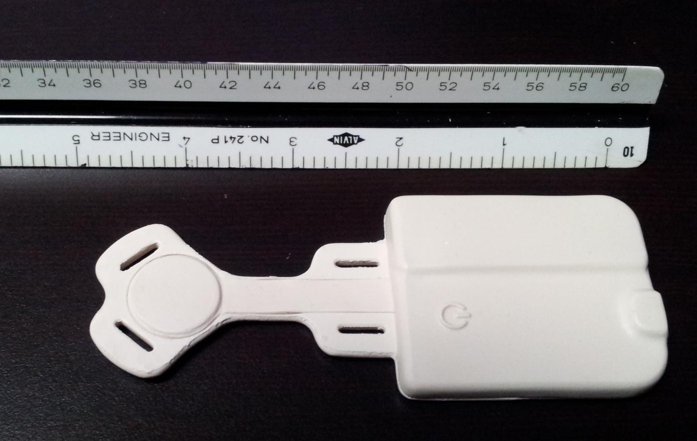
NCEE Labs FCC ID: QQIBV2014 External Photos Figure 1 - Top Figure 2 - Bottom
NCEE Labs FCC ID: QQIBV2014 Device Label Figure 1 - Label Location Figure 2 - FCC ID Label Label material is permanently affixed using a weatherproof vinyl material. The full FCC statement is not included because the available space on the device is less than the palm of a hand. The FCC statement is placed in the user’s manual per KDB 784748 D01 Section 2.2.
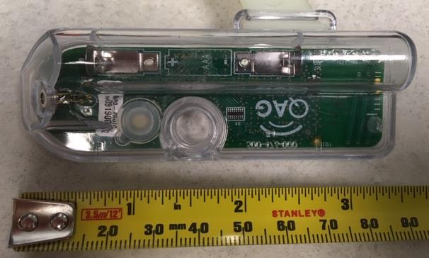
NCEE Labs FCC ID: QQIBV2014 Internal Photos Figure 1 - Bottom of Device NCEE Labs FCC ID: QQIBV2014 Internal Photos Figure 2 - Top of Device NCEE Labs FCC ID: QQIBV2014 Internal Photos Figure 3 - PCB Detail
Nebraska Center for Excellence in Electronics 4740 Discovery Drive Lincoln, NE 68521 Phone: 402.323.6233 Fax: 402.323.6238 RF Exposure Applicant: Communication Systems Solutions, LLC Device: Baby Vida Page 1 of 2 From KDB 447498 D01 v05: The 1-g and 10-g SAR test exclusion thresholds for 100 MHz to 6 GHz at test separation distances ≤50 mm are determined by: [(max. power of channel, including tune-up tolerance, mW)/(min. test separation distance, mm)] · [√f(GHz)] ≤3.0 for 1-g SAR and ≤7.5 for 10-g extremity SAR, where ・ f(GHz) is the RF channel transmit frequency in GHz ・ Power and distance are rounded to the nearest mW and mm before calculation17 ・ The result is rounded to one decimal place for comparison The test exclusions are applicable only when the minimum test separation distance is ≤50 mm and for transmission frequencies between 100 MHz and 6 GHz. When the minimum test separation distance is < 5 mm, a distance of 5 mm is applied to determine SAR test exclusion *Note: minimum separation distance was defined as the closest point from the transmitting antenna to human tissue. It is assumed that the user could hold the remote from any point on the outside case. Taken from NCEE Labs test report R20140505-23-FCC, Section 4.4. Nebraska Center for Excellence in Electronics 4740 Discovery Drive Lincoln, NE 68521 Phone: 402.323.6233 Fax: 402.323.6238 RF Exposure Applicant: Communication Systems Solutions, LLC Device: Baby Vida Page 2 of 2 Lowest Channel f(GHz) = 2.402 Power = 2.60 dBm = 1.82 mW, round to nearest mW = 2 mW Minimum separation distance = 5.00 mm (device is handheld and transmitting antenna can be less than 5 mm, so the 5 mm minimum was used) [2.00 mW] / [5.00 mm] • [√2.402 ] = 0.6 Limit = 3.0 2.60 dBm was taken from NCEE Labs test report R20140505-23-FCC, Section 4.4. Middle Channel f(GHz) = 2.442 Power = 4.51 dBm = 2.82 mW, rounded to nearest mW = 3 mW Minimum separation distance = 5.00 mm (device is handheld and transmitting antenna can be less than 5 mm, so the 5 mm minimum was used) [3 mW] / [5.00 mm] • [√2.442 ] = 0.9 Limit = 3.0 4.51 dBm was taken from NCEE Labs test report R20140505-23-FCC, Section 4.4. Highest Channel f(GHz) = 2.480 Power = 3.24 dBm = 2.11 mW, rounded to nearest mW = 2 mW Minimum separation distance = 5.00 mm (device is handheld and transmitting antenna can be less than 5 mm, so the 5 mm minimum was used) [2 mW] / [5.00 mm] • [√2.480 ] = 0.6 Limit = 3.0 3.24 dBm was taken from NCEE Labs test report R20140505-23-FCC, Section 4.4.
The Nebraska Center for Excellence in Electronics (NCEE) authorizes the above named company to reproduce this report provided it is reproduced in its entirety for use by the company’s employees only. Any use that a third party makes of this report, or any reliance on or decisions made based on it, are the responsibility of such third parties. NCEE accepts no responsibility for damages, if any, suffered by any third party as a result of decisions made or actions based on this report. This report applies only to the items tested. FCC/IC TEST REPORT Applicant: Communications Systems Solutions Address: 6030 S. 58th St. STE C Lincoln, NE 68516 Product: Baby Vida FCC ID: QQIBV2014 Test Report No: R20140505A-23-FCC Approved By: __________________ Nic S. Johnson, NCE Technical Manager iNARTE Certified EMC Engineer #EMC-003337-NE Date: 13 November 2014 Total Pages: 45 NCEE Labs Report Number: R20140505-23-FCC Test Report Applicant: Communications Systems Solutions The Nebraska Center for Excellence in Electronics 4740 Discovery Drive Lincoln, NE 68521 Page 2 of 45 Tables of Figures Table of Tables 1.0 Summary of test results 1.1 Test Results 1.2 Test Methods 1.2.1 Radiated Emissions 2.0 Description 2.1 Equipment under test 2.2 Laboratory description 2.3 Description of test modes 2.4 Applied standards 2.5 Description of support units 2.6 Configuration of system under test 3.0 Test equipment used 4.0 Detailed Results 4.1 Unique antenna requirement 4.2 Radiated Emissions 4.3 Bandwidth 4.4 Maximum peak output power 4.5 Bandedges 4.6 Power spectral density Appendix A – Test photos Appendix B – Sample calculation Appendix C – RF exposure evaluation NCEE Labs Report Number: R20140505-23-FCC Test Report Applicant: Communications Systems Solutions The Nebraska Center for Excellence in Electronics 4740 Discovery Drive Lincoln, NE 68521 Page 3 of 45 Table of Figures Figure Page Number Figure 1 - Radiated Emissions Test Setup __________________________________________ 11 Figure 2 – Baby Vida Duty Cycle _________________________________________________ 12 Figure 3 - Radiated Emissions Plot, Receive ________________________________________ 13 Figure 4 - Radiated Emissions Plot, Channel 1 ______________________________________ 15 Figure 5 - Radiated Emissions Plot, Channel 2 ______________________________________ 17 Figure 6 - Radiated Emissions Plot, Channel 3 ______________________________________ 19 Figure 8 - 6dB Bandwidth, Low Channel ____________________________________________ 23 Figure 9 - 6dB Bandwidth, Middle Channel__________________________________________ 24 Figure 10 - 6dB Bandwidth, High Channel __________________________________________ 25 Figure 11 - 99% Occupied Bandwidth, Low Channel __________________________________ 26 Figure 12 - 99% Occupied Bandwidth, Mid Channel __________________________________ 27 Figure 13 - 99% Occupied Bandwidth, High Channel __________________________________ 28 Figure 14 - Power Measurements Test Setup _______________________________________ 29 Figure 15 - Band-edge Measurement, Low Channel, Un-Restricted ______________________ 33 Figure 16 - Band-edge Measurement, Low Channel, Restricted _________________________ 34 Figure 17 - Band-edge Measurement, Low Channel, Restricted _________________________ 35 Figure 18 - Band-edge Measurement, High Channel, Restricted _________________________ 36 Figure 19 - Band-edge Measurement, High Channel, Restricted _________________________ 37 Figure 20 - Power Spectral Density Measurement, Low Channel ________________________ 40 Figure 21 - Power Spectral Density Measurement, Mid Channel _________________________ 41 Figure 22 - Power Spectral Density Measurement, High Channel ________________________ 42 Figure 23 – Radiated Emissions Test Setup _________________________________________ 43 Figure 24 - Radiated Emissions Test Setup _________________________________________ 43 Table Page Number Table 1 - Radiated Emissions Quasi-peak Measurements, Receive ______________________ 14 Table 2 - Radiated Emissions Peak Measurements, Receive ___________________________ 14 Table 3 - Radiated Emissions Quasi-peak Measurements, Channel 1 ____________________ 16 Table 4 - Radiated Emissions Average Measurements, Channel 1 _______________________ 16 Table 5 - Radiated Emissions Peak Measurements, Channel 1 _________________________ 16 Table 6 - Radiated Emissions Quasi-peak Measurements, Channel 2 ____________________ 18 Table 7 - Radiated Emissions Average Measurements, Channel 2 _______________________ 18 Table 8 - Radiated Emissions Peak Measurements, Channel 2 _________________________ 18 Table 9 - Radiated Emissions Quasi-peak Measurements, Channel 3 ____________________ 20 Table 10 - Radiated Emissions Average Measurements, Channel 3 ______________________ 20 Table 11 - Radiated Emissions Peak Measurements, Channel 3 ________________________ 20 NCEE Labs Report Number: R20140505-23-FCC Test Report Applicant: Communications Systems Solutions The Nebraska Center for Excellence in Electronics 4740 Discovery Drive Lincoln, NE 68521 Page 4 of 45 1.0 Summary of test results 1.1 Test Results The EUT has been tested according to the following specifications: APPLIED STANDARDS: FCC Part 15, Subpart C Industry Canada RSS-Gen, RSS-210 Issue 8 Standard Section Test Type and Limit Result Remark 15.203 RSS-Gen Unique Antenna Requirement Pass Permanently attached antenna 15.209 RSS-Gen Radiated Emissions Pass Meets the requirement of the limit. 15.247(a)(1) RSS-210 Issue 8 Minimum Bandwidth, Limit Min. 500kHz Pass Meets the requirement of the limit. 15.249 RSS-210 Issue 8 Minimum Bandwidth Pass Meets the requirement of the limit. 15.247(b), 15.247 RSS-210 Issue 8 Maximum Peak Output Power, Limit: Pass Meets the requirement of the limit. 15.247(c) , 15.247 RSS-210 Issue 8 Transmitter Radiated Emissions, Limit: Table 15.209 Pass Meets the requirement of the limit. 15.247(c) RSS-210 Issue 8 Band Edge Measurement, Limit: 20dB less than the peak value of …
Text truncated - open the document above for the full version.
NCEE Labs FCC ID: QQIBV2014 Test Setup Photos Figure 1 - Test Setup Photo, Vertical Orientation NCEE Labs FCC ID: QQIBV2014 Test Setup Photos Figure 2 - Test Setup Photo, Horizontal Orientation NCEE Labs FCC ID: QQIBV2014 Test Setup Photos Figure 3 - Test Setup Photo, Vertical Orientation
6030 S. 58th Street · Lincoln · United States
| # | Rule Parts | Frequency Range | Power Output |
|---|---|---|---|
| 1 | 15C | 2.40 GHz - 2.48 GHz | 2.80 mW |

Ear Tag
Equipment Class
DTS - Digital Transmission System