QQRBPS91W60Bi-directional Amplifier
Coverage Solutions Corporation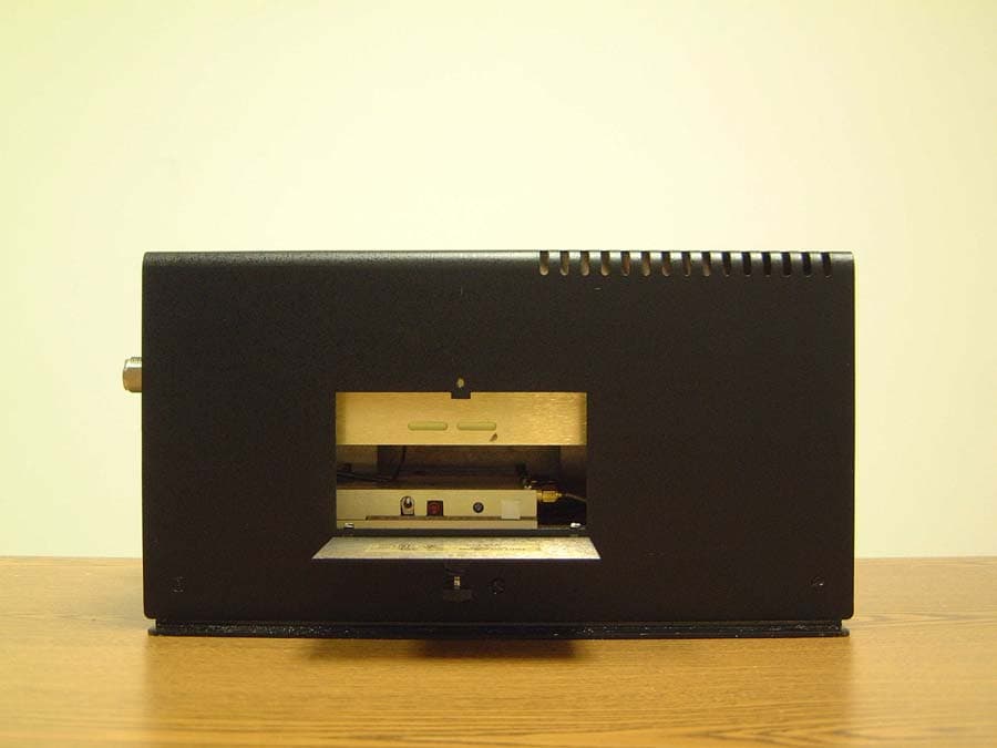
Click to zoom
Application Details
- Equipment Class
- AMP - Amplifier
- Date of Grant
- Jan 07, 2003
- Application Purpose
- Original Equipment
- Date of Application
- Jan 07, 2003
- Equipment Note
- Bi-directional Amplifier
- Frequency Range
- 935.00000000 - 941.00000000
- Country
- United States
Documents & Files
Document Text
Text extracted from the exhibit documents filed with the FCC. Open a document above to read the original.
Users Manual
INSTALLATION AND OPERATING MANUAL FOR BDA-XXX-1/1W-60-A BI-DIRECTIONAL AMPLIFIER TABLE OF CONTENTS PARAGRAPH PAGE NO BDA OVERVIEW 3 BDA BLOCK DIAGRAM DESCRIPTION 3 BDA BLOCK DIAGRAM DRAWING (Figure 1) 4 ELECTRICAL SPECIFICATIONS 5 FREQUENCY RANGES (Table 1) 6 MECHANICAL SPECIFICATIONS 7 ENVIRONMENTAL CONDITIONS 7 BDA CONNECTIONS 7 MECHANICAL OUTLINE DRAWING (Figure 2) 8 RF EXPOSURE WARNING 9 BDA INSTALLATION 10 BDA OPERATION 11 MECHANICAL OUTLINE- ADJUSTMENT (Figure 3) 12 DIAGNOSTICS GUIDE 13 Page 2 BDA OVERVIEW: The BDA assembly extends the coverage area of radio communications in buildings and RF shielded environments. The unit features low noise figure and wide dynamic range. It is based on a duplexed path configuration with sharp out of band attenuation allowing improved isolation between the receiving and transmitting paths. BDA BLOCK DIAGRAM DESCRIPTION : Refer to figure 1 for the following discussion. The BDA Downlink path receives RF signals from the base station and amplifies and transmits them to the subscriber. The BDA Uplink path receives RF signals from the subscriber and amplifies and transmits them to the base station. The Uplink and Downlink occupy two distinct frequency bands. For example, the SMR frequency bands are as follows: 806-821 MHz for the Uplink and 851-866 MHz for the Downlink. Two diplexers isolate the paths and route each signal to the proper amplifying channel. A selectable Automatic Level Control (ALC) allows for output power limiting. A Manual Gain Control (MGC) provides continuous control of amplifier gain. The use of these controls is covered in the “OPERATION” section, later in this document. Page 3 Figure 1 Page 4 ELECTRICAL SPECIFICATIONS : Frequency Range : See Table 1 Pass band Gain @ min attenuation : 60 dB minimum Manual Gain Control Range : 15 dB minimum (continuous) Pass band Ripple : ±1.5 dB typical Noise Figure @+25 °C at max gain : 5.0 dB max 3rd Order Intercept point Uplink : +45 dBm typical Downlink : +45 dBm typical Output Power @ 1dB Compression Uplink : +32 dBm (typ) Downlink : +32 dBm (typ) Isolation between Up/Down Link : 80 dB min Input/ Output Impedance : 50 Ohms VSWR (Input/Output) : 1.5: 1 max Power Supply : 110VAC/0.67Amp : 240VAC/0.34 Amp : 50 to 60 Hz Page 5 Table 1 Frequency Band Downlink Frequency Ranges Uplink Frequency Ranges SMR 851-866 MHz 806-821 MHz CELL A 869-880 MHz 824-835 MHz CELL B 880-894 MHz 835-849 MHz CELL AB 869-894 MHz 824-849 MHz GSM F 935-960 MHz 890-915 MHz GSM H 947-960 MHz 902-915 MHz GSM L 935-947 MHz 890-902 MHZ NPS PAC 866-869 MHz 821-824 MHz 2PG 929-942 MHz 898-904 MHz 2PGN 929-942 MHz 900-903 MHz PS8 851-869 MHz 806-824 MHz PS9 935-941 MHz 896-902 MHz Page 6 MECHANICAL SPECIFICATIONS : Size : 11.2 x 9.7 x 6.0 inch : (284.5 x 246.4 x 152.4 mm) RF Connectors : N-type Female Weight : 13.5 Lbs. (6.2kg.) approx. ENVIRONMENTAL CONDITIONS: The unit is designed for indoor applications: Operating temperature: - 20°C to + 50°C Storage temperature: - 50°C to + 90°C BDA CONNECTIONS The BDA AC power is accepted through a standard 3-wire male plug (IEC-320) with phase, neutral and ground leads. The AC power is wired to a high efficiency DC switching power supply which is CE and UL approved. The power supply runs the amplifiers and the Power On lamp. The metal enclosure of the BDA is connected to ground. A 9-pin D-Sub connector provides failure alarm output contacts (see diagram next page) as well as an optional 12 VDC (250mA) auxiliary output. The RF connections are made via two type “N” female connectors. The RF connector labeled “BASE” must be connected to the antenna pointing towards the base station. The RF connection labeled “MOBILE” must be connected to the antenna facing the area to be covered by the BDA. The RF connections must be made through cables with characteristic impedance of 50 ohms. The isolation between the base station antenna and the mobile antenna should be at least 12 dB higher than the BDA gain. Isolation less than this value can cause gain ripple across the band. Isolation equal to or less than the BDA gain will give rise to oscillations which will saturate the amplifiers and possibly cause damage to the BDA. Page 7 Figure 2 IN BUILDING REPEATER BDA Mechanical Outline Page 8 RF EXPOSURE WARNING In order to satisfy the FCC RF exposure requirements, the BDA/antenna installation must comply with the following: The outdoor antenna (Yagi type or similar directional antenna) must be installed so as to provide a minimum separation distance of 0.3 meters (30 cm) between the antenna and persons within the area. (This assumes a typical antenna with gain of [10.1 dBi, VSWR ≤ 1.5:1, Zo= 50 ohms, and a cable attenuation of between 1-10 dB). The indoor antenna (omni directional) must be installed so as to provide a minimum separation distance of 0.2 meters (20 cm) between the antenna and persons within the area. (This assumes a typical wide-beam type antenna with gain of 0-2 dBi, VSWR ≤ 2:1, Zo= 50 ohms, and a cable attenuation of between 1-10 dB). Page 9 BDA INSTALLATION DO NOT APPLY A.C. POWER TO THE BDA UNTIL CABLES ARE CONNECTED TO BOTH PORTS OF THE BDA AND THE ANTENNAS. 1. Mount the BDA on the wall with the RF connectors pointing DOWN. Using appropriate screws and anchors, attach the BDA to the wall at the four mounting holes on the side flanges. 2. Ensure that the isolation between the donor antenna and the service antenna is at least 12 dB greater than the BDA gain. (Use the higher of the Uplink and Downlink gains reported on the BDA test data sheet). 3. Connect the cable from the donor antenna to the BDA connector labeled “BASE” and the cable from the service antennas to the BDA connector labeled “MOBILE”. 4. Open the adjustment access panels on the sides of the BDA and verify that both of the ALC switches are in their factory preset “ON” positions. Close the panels. 5. Connect the AC power cord to the BDA and then to the power source. Verify that the “Power ON” lamp is illuminated. Installation…
Text truncated - open the document above for the full version.
Cover Letter(s)
CSC Coverage Solutions Corporation 2901 W. Busch Blvd. Suite 900 Tampa, Florida 33618 Tel 813-931-1415 Fax 813-935-9458 e-mail [email protected] website: www.coveragesolutions.net December 19, 2002 Federal Communications Commission Office of Engineering and Technology 7435 Oakland Mills Rd. Columbia, MD 21046 Subject: Request for Confidentiality Dear Sir or Madam: Coverage Solutions Corporation respectfully requests that the schematic diagrams, block diagram, and circuit descriptions submitted with the application for certification under FCC ID QQRBPS91W60 be withheld from public disclosure. This request is made under the provisions of Section 0.457 (d) of the Commission’s rules and Section 0.552 (b) (4) of the Freedom of Information Act. This product has been developed at considerable expense, and disclosure of this information would place Coverage Solutions Corporation at a competitive disadvantage. Thank you for your attention to this matter. Sincerely yours, Coverage Solutions Corporation Richard Parker Richard Parker President
Parts List/Tune Up Info
INSTALLATION AND OPERATING MANUAL FOR BDA-XXX-1/1W-60-A BI-DIRECTIONAL AMPLIFIER TABLE OF CONTENTS PARAGRAPH PAGE NO BDA OVERVIEW 3 BDA BLOCK DIAGRAM DESCRIPTION 3 BDA BLOCK DIAGRAM DRAWING (Figure 1) 4 ELECTRICAL SPECIFICATIONS 5 FREQUENCY RANGES (Table 1) 6 MECHANICAL SPECIFICATIONS 7 ENVIRONMENTAL CONDITIONS 7 BDA CONNECTIONS 7 MECHANICAL OUTLINE DRAWING (Figure 2) 8 RF EXPOSURE WARNING 9 BDA INSTALLATION 10 BDA OPERATION 11 MECHANICAL OUTLINE- ADJUSTMENT (Figure 3) 12 DIAGNOSTICS GUIDE 13 Page 2 BDA OVERVIEW: The BDA assembly extends the coverage area of radio communications in buildings and RF shielded environments. The unit features low noise figure and wide dynamic range. It is based on a duplexed path configuration with sharp out of band attenuation allowing improved isolation between the receiving and transmitting paths. BDA BLOCK DIAGRAM DESCRIPTION : Refer to figure 1 for the following discussion. The BDA Downlink path receives RF signals from the base station and amplifies and transmits them to the subscriber. The BDA Uplink path receives RF signals from the subscriber and amplifies and transmits them to the base station. The Uplink and Downlink occupy two distinct frequency bands. For example, the SMR frequency bands are as follows: 806-821 MHz for the Uplink and 851-866 MHz for the Downlink. Two diplexers isolate the paths and route each signal to the proper amplifying channel. A selectable Automatic Level Control (ALC) allows for output power limiting. A Manual Gain Control (MGC) provides continuous control of amplifier gain. The use of these controls is covered in the “OPERATION” section, later in this document. Page 3 Figure 1 Page 4 ELECTRICAL SPECIFICATIONS : Frequency Range : See Table 1 Pass band Gain @ min attenuation : 60 dB minimum Manual Gain Control Range : 15 dB minimum (continuous) Pass band Ripple : ±1.5 dB typical Noise Figure @+25 °C at max gain : 5.0 dB max 3rd Order Intercept point Uplink : +45 dBm typical Downlink : +45 dBm typical Output Power @ 1dB Compression Uplink : +32 dBm (typ) Downlink : +32 dBm (typ) Isolation between Up/Down Link : 80 dB min Input/ Output Impedance : 50 Ohms VSWR (Input/Output) : 1.5: 1 max Power Supply : 110VAC/0.67Amp : 240VAC/0.34 Amp : 50 to 60 Hz Page 5 Table 1 Frequency Band Downlink Frequency Ranges Uplink Frequency Ranges SMR 851-866 MHz 806-821 MHz CELL A 869-880 MHz 824-835 MHz CELL B 880-894 MHz 835-849 MHz CELL AB 869-894 MHz 824-849 MHz GSM F 935-960 MHz 890-915 MHz GSM H 947-960 MHz 902-915 MHz GSM L 935-947 MHz 890-902 MHZ NPS PAC 866-869 MHz 821-824 MHz 2PG 929-942 MHz 898-904 MHz 2PGN 929-942 MHz 900-903 MHz PS8 851-869 MHz 806-824 MHz PS9 935-941 MHz 896-902 MHz Page 6 MECHANICAL SPECIFICATIONS : Size : 11.2 x 9.7 x 6.0 inch : (284.5 x 246.4 x 152.4 mm) RF Connectors : N-type Female Weight : 13.5 Lbs. (6.2kg.) approx. ENVIRONMENTAL CONDITIONS: The unit is designed for indoor applications: Operating temperature: - 20°C to + 50°C Storage temperature: - 50°C to + 90°C BDA CONNECTIONS The BDA AC power is accepted through a standard 3-wire male plug (IEC-320) with phase, neutral and ground leads. The AC power is wired to a high efficiency DC switching power supply which is CE and UL approved. The power supply runs the amplifiers and the Power On lamp. The metal enclosure of the BDA is connected to ground. A 9-pin D-Sub connector provides failure alarm output contacts (see diagram next page) as well as an optional 12 VDC (250mA) auxiliary output. The RF connections are made via two type “N” female connectors. The RF connector labeled “BASE” must be connected to the antenna pointing towards the base station. The RF connection labeled “MOBILE” must be connected to the antenna facing the area to be covered by the BDA. The RF connections must be made through cables with characteristic impedance of 50 ohms. The isolation between the base station antenna and the mobile antenna should be at least 12 dB higher than the BDA gain. Isolation less than this value can cause gain ripple across the band. Isolation equal to or less than the BDA gain will give rise to oscillations which will saturate the amplifiers and possibly cause damage to the BDA. Page 7 Figure 2 IN BUILDING REPEATER BDA Mechanical Outline Page 8 RF EXPOSURE WARNING In order to satisfy the FCC RF exposure requirements, the BDA/antenna installation must comply with the following: The outdoor antenna (Yagi type or similar directional antenna) must be installed so as to provide a minimum separation distance of 0.3 meters (30 cm) between the antenna and persons within the area. (This assumes a typical antenna with gain of [10.1 dBi, VSWR ≤ 1.5:1, Zo= 50 ohms, and a cable attenuation of between 1-10 dB). The indoor antenna (omni directional) must be installed so as to provide a minimum separation distance of 0.2 meters (20 cm) between the antenna and persons within the area. (This assumes a typical wide-beam type antenna with gain of 0-2 dBi, VSWR ≤ 2:1, Zo= 50 ohms, and a cable attenuation of between 1-10 dB). Page 9 BDA INSTALLATION DO NOT APPLY A.C. POWER TO THE BDA UNTIL CABLES ARE CONNECTED TO BOTH PORTS OF THE BDA AND THE ANTENNAS. 1. Mount the BDA on the wall with the RF connectors pointing DOWN. Using appropriate screws and anchors, attach the BDA to the wall at the four mounting holes on the side flanges. 2. Ensure that the isolation between the donor antenna and the service antenna is at least 12 dB greater than the BDA gain. (Use the higher of the Uplink and Downlink gains reported on the BDA test data sheet). 3. Connect the cable from the donor antenna to the BDA connector labeled “BASE” and the cable from the service antennas to the BDA connector labeled “MOBILE”. 4. Open the adjustment access panels on the sides of the BDA and verify that both of the ALC switches are in their factory preset “ON” positions. Close the panels. 5. Connect the AC power cord to the BDA and then to the power source. Verify that the “Power ON” lamp is illuminated. Installation…
Text truncated - open the document above for the full version.
RF Exposure Info
Prediction of MPE limit at a given distance Equation from page 18 of OET Bulletin 65, Edition 97-01 where:S = power density P = power input to the antenna G = power gain of the antenna in the direction of interest relative to an isotropic radiator R = distance to the center of radiation of the antenna Maximum peak output power at antenna input terminal:26.00(dBm) Maximum peak output power at antenna input terminal:398.1071706(mW) Antenna gain(typical):10.1(dBi) Maximum antenna gain:10.23292992(numeric) Prediction distance:30(cm) Prediction frequency:900(MHz) MPE limit for uncontrolled exposure at prediction frequency:0.6(mW/cm^2) Power density at prediction frequency:0.360203(mW/cm^2) Margin of compliance at 30 cm:-2.2(dB) 2 4R PG S π =
RF Exposure Info
Prediction of MPE limit at a given distance Equation from page 18 of OET Bulletin 65, Edition 97-01 where:S = power density P = power input to the antenna G = power gain of the antenna in the direction of interest relative to an isotropic radiator R = distance to the center of radiation of the antenna Maximum peak output power at antenna input terminal:26.00(dBm) Maximum peak output power at antenna input terminal:398.1071706(mW) Antenna gain(typical):2(dBi) Maximum antenna gain:1.584893192(numeric) Prediction distance:20(cm) Prediction frequency:900(MHz) MPE limit for uncontrolled exposure at prediction frequency:0.6(mW/cm^2) Power density at prediction frequency:0.125525(mW/cm^2) Margin of compliance at 20 cm:-6.8(dB) 2 4R PG S π =
Test Report
Nemko Test Report: 2L0584RUS2 Applicant: Coverage Solutions Corp. Equipment Under Test: BDA-PS9-1/1W-60-A (E.U.T.) In Accordance With: FCC Part 24, Subpart D Narrowband PCS Repeater FCC Part 90, Subpart I SMR Repeater Tested By: Nemko Dallas Inc. 802 N. Kealy Lewisville, TX 75057-3136 Authorized By: Tom Tidwell, Wireless/EMC Manager Date: 1/8/02 Total Number of Pages: 77 Nemko Dallas FCC PART 24, SUBPART D and FCC PART 90, SUBPART I RADIO REPEATER EQUIPMENT: BDA-PS9-1/1W-60-A PROJECT NO.: 2L0584RUS2 Page 2 of 77 Table of Contents Section 1. Summary of Test Results...................................................................................3 Section 2. General Equipment Specification.......................................................................5 Section 3. RF Power Output..............................................................................................7 Section 4. Occupied Bandwidth.........................................................................................8 Section 5. Spurious Emissions at Antenna Terminals........................................................21 Section 6. Field Strength of Spurious...............................................................................62 Section 7. Test Equipment List........................................................................................67 ANNEX A - TEST METHODOLOGIES................................................................................68 ANNEX B - TEST DIAGRAMS............................................................................................74 Nemko Dallas FCC PART 24, SUBPART D and FCC PART 90, SUBPART I RADIO REPEATER EQUIPMENT: BDA-PS9-1/1W-60-A PROJECT NO.: 2L0584RUS2 Page 3 of 77 Section 1. Summary of Test Results Manufacturer: Coverage Solutions Corp. Model No.: BDA-PS9-1/1W-60-A Serial No.: 02111011 General: All measurements are traceable to national standards. These tests were conducted on a sample of the equipment for the purpose of demonstrating compliance with FCC Part 24, Subpart D. New Submission Production Unit Class II Permissive Change Pre-Production Unit THIS TEST REPORT RELATES ONLY TO THE ITEM(S) TESTED. THE FOLLOWING DEVIATIONS FROM, ADDITIONS TO, OR EXCLUSIONS FROM THE TEST SPECIFICATIONS HAVE BEEN MADE: None Nemko Dallas Inc. authorizes the above named company to reproduce this report provided it is reproduced in its entirety and for use by the company’s employees only. Any use which a third party makes of this report, or any reliance on or decisions to be made based on it, are the responsibility of such third parties. Nemko Dallas Inc. accepts no responsibility for damages, if any, suffered by any third party as a result of decisions made or actions based on this report. This report applies only to the items tested. Nemko Dallas FCC PART 24, SUBPART D and FCC PART 90, SUBPART I RADIO REPEATER EQUIPMENT: BDA-PS9-1/1W-60-A PROJECT NO.: 2L0584RUS2 Page 4 of 77 Summary Of Test Data NAME OF TEST SPEC. RESULT RF Power Output < Rated Complies Occupied Bandwidth (2FSK) < Rated Complies Occupied Bandwidth (4FSK) < Rated Complies Occupied Bandwidth (iDEN) < Rated Complies Spurious Emissions at Antenna Terminals (Part 24) -13 dBm Complies Field Strength of Spurious Emissions (Part 24) -13 dBm E.R.P. Complies Spurious Emissions at Antenna Terminals (Part 90) -20 dBm Complies Field Strength of Spurious Emissions (Part 90) -20 dBm E.R.P. Complies Frequency Stability ± 1 ppm N/A Footnotes: The device has no modulation circuitry , therefore this test was not performed. Nemko Dallas FCC PART 24, SUBPART D and FCC PART 90, SUBPART I RADIO REPEATER EQUIPMENT: BDA-PS9-1/1W-60-A PROJECT NO.: 2L0584RUS2 Page 5 of 77 Section 2. General Equipment Specification Supply Voltage Input: 115 Vac Frequency Bands: FSK Uplink 896.015 to 901.985 MHz FSK Downlink 935.015 to 940.985 MHz QAM Uplink 896.02 to 901.98 MHz QAM Downlink 935.02 to 940.98 MHz 2FSK (F2D) 4FSK (F2D) iDEN (QAM) (D7W) Type of Modulation and Designator: System Gain: 60 dB Output Impedance: 50 ohms RF Output (Rated): Uplink Total 2 Watts (Part 24 bands) Downlink Total 2 Watts (Part 24 bands) Uplink Total .398 Watts (Part 90 bands) Downlink Total .398 Watts (Part 90 bands) Nemko Dallas FCC PART 24, SUBPART D and FCC PART 90, SUBPART I RADIO REPEATER EQUIPMENT: BDA-PS9-1/1W-60-A PROJECT NO.: 2L0584RUS2 Page 6 of 77 System Description This is an F1/F1 repeater operating in the narrowband PCS band and the SMR radio band. System Diagram Nemko Dallas FCC PART 24, SUBPART D and FCC PART 90, SUBPART I RADIO REPEATER EQUIPMENT: BDA-PS9-1/1W-60-A PROJECT NO.: 2L0584RUS2 Page 7 of 77 Section 3. RF Power Output NAME OF TEST: RF Power Output PARA. NO.: 2.1046 TESTED BY: David Light DATE: 12/4/2002 Test Results: Complies. Measurement Data: Modulation Type Frequency (MHz) Output Power (dBm) Output Power (W) 2FSK 900 +26 .398 4FSK 900 +26 .398 QAM 900 +26 .398 2FSK 940 +26 .398 4FSK 940 +26 .398 QAM 940 +26 .398 In the Part 90 bands, the maximum rf power output to meet the spurious limit is +26dBm. Intermodulation tests were performed with two carriers at +23 dBm/carrier. The ALC control on the amplifier will maintain the maximum rf output of +26 dBm (.398). Measurement uncertainty: +/- 0.7 dB Test Equipment: 1029-1030 Nemko Dallas FCC PART 24, SUBPART D and FCC PART 90, SUBPART I RADIO REPEATER EQUIPMENT: BDA-PS9-1/1W-60-A PROJECT NO.: 2L0584RUS2 Page 8 of 77 Section 4. Occupied Bandwidth NAME OF TEST: Occupied Bandwidth PARA. NO.: 2.1049 TESTED BY: David Light DATE: 12/05/2002 Test Results: Complies. Test Data: See attached plots. Measurement Uncertainty: +/- 1.7 dB Nemko Dallas FCC PART 24, SUBPART D and FCC PART 90, SUBPART I RADIO REPEATER EQUIPMENT: BDA-PS9-1/1W-60-A PROJECT NO.: 2L0584RUS2 Page 9 of 77 Part 24 and Part 90 Test Data – Occupied Bandwidth Dallas Headquarters: 802 N. Kealy Lewisville, TX 75057 Tel: (972) 436-9600 Fax: (972) 436-2667 Nemko Dallas, Inc. Data Plot Page 1 of6 Complete X Job No.:2L0585R Date:12/…
Text truncated - open the document above for the full version.
Test Report
Nemko Dallas FCC PART 24, SUBPART D and FCC PART 90, SUBPART I RADIO REPEATER EQUIPMENT: BDA-PS9-1/1W-60-A PROJECT NO.: 2L0584RUS2 Page 5 of 77 Section 2. General Equipment Specification Supply Voltage Input: 115 Vac Frequency Bands: FSK Uplink 896.015 to 901.985 MHz FSK Downlink 935.015 to 940.985 MHz QAM Uplink 896.02 to 901.98 MHz QAM Downlink 935.02 to 940.98 MHz 2FSK (F2D) 4FSK (F2D) iDEN (QAM) (D7W) Type of Modulation and Designator: System Gain: 60 dB Output Impedance: 50 ohms RF Output (Rated): Uplink Total .398 Watts Downlink Total .398 Watts
Test Report
FCC ID: QQRBPS91W60 RF OUTPUT STAGE BIASING IN BDA-PS9-1/1W-60 BDA. Uplink: Output stage: Motorola MHL-9236 D.C. bias: 26.4 Volts @ 550 mA, typ. Downlink: Output stage: Motorola MHL-9236 D.C. bias: 26.4 Volts @ 550 mA, typ. Page 1 of 7
Test Setup Photos
Nemko Dallas FCC PART 24, SUBPART D and FCC PART 90, SUBPART I RADIO REPEATER EQUIPMENT: BDA-PS9-1/1W-60-A PROJECT NO.: 2L0584RUS2 Page 65 of 77 Photographs of Test Setup Nemko Dallas FCC PART 24, SUBPART D and FCC PART 90, SUBPART I RADIO REPEATER EQUIPMENT: BDA-PS9-1/1W-60-A PROJECT NO.: 2L0584RUS2 Page 66 of 77
Contact Information
Applicant
Richard Parker(President)
Test Firm
Nemko Canada Inc.Stuart Beck
Technical Specifications
| # | Rule Parts | Frequency Range | Power Output | Emission | Tolerance |
|---|---|---|---|---|---|
| 4 | 9 | 935 MHz - 941 MHz | 398.00 mW | D7W | Amp |
Other Applications from Coverage Solutions Corporation
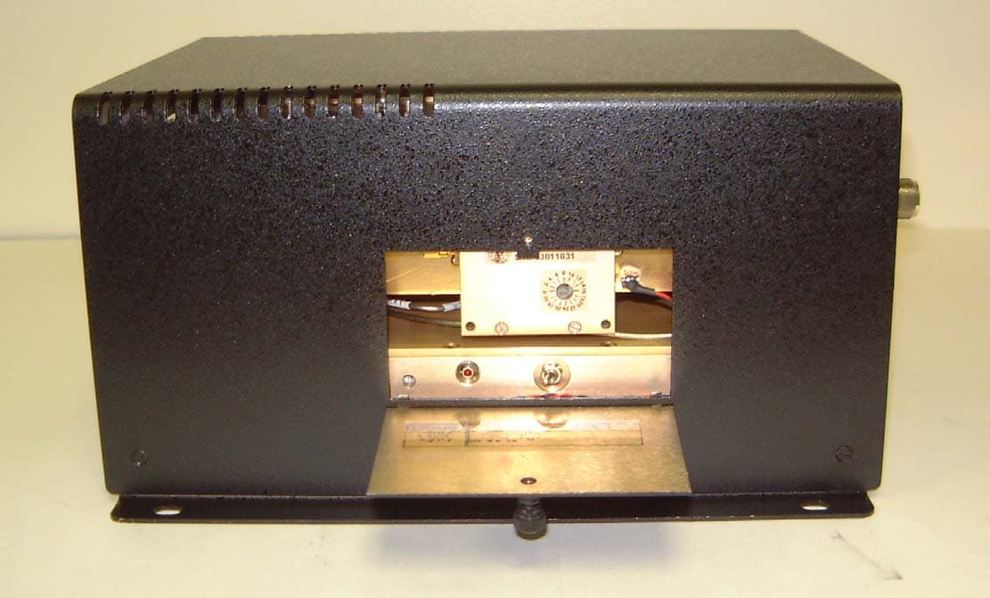
QQRBPCSAC1W80B
Nov 12, 2003Bi-Directional Amplifier
Equipment Class
AMP - Amplifier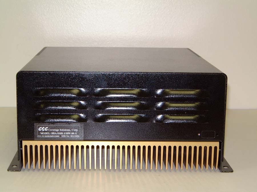
QQRBSMR10W80
Jan 13, 2003Bi-directional Amplifier
Equipment Class
AMP - Amplifier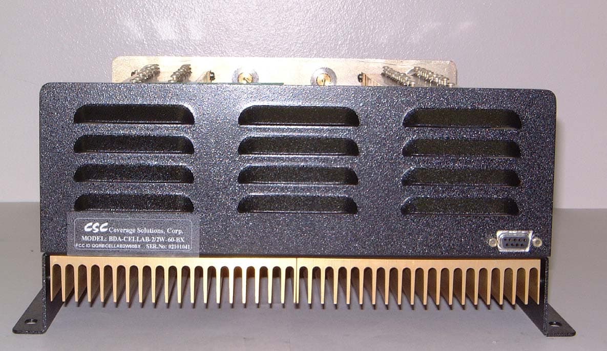
QQRBCELLAB2W60BX
Jan 09, 2003Bi-directional Amplifier
Equipment Class
AMP - Amplifier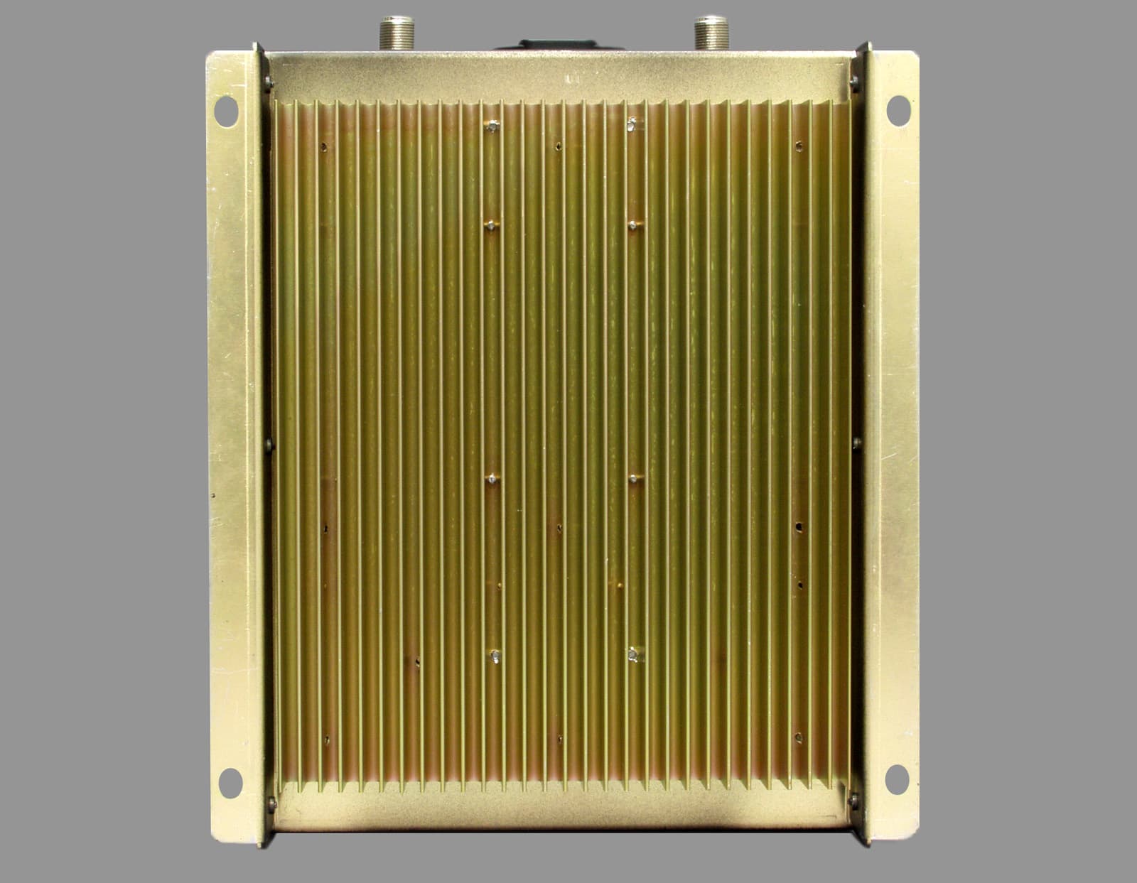
QQRCELLB1W60
Jan 07, 2003Bi-directional Amplifier
Equipment Class
AMP - Amplifier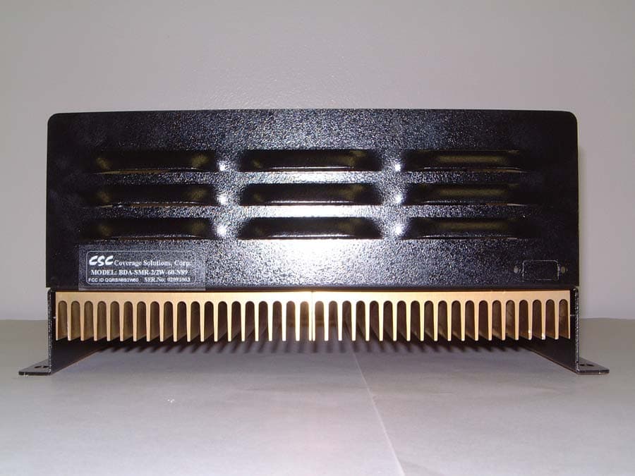
QQRBN892W60
Jan 07, 2003Bi-directional Amplifier
Equipment Class
AMP - Amplifier