QQZ1XRTTAGENT1XRTT Tracking Device
Coleman Technologies, Inc.Application Details
- Equipment Class
- PCB - PCS Licensed Transmitter
- Date of Grant
- Apr 27, 2004
- Application Purpose
- Original Equipment
- Date of Application
- Apr 27, 2004
- Equipment Note
- 1XRTT Tracking Device
- Frequency Range
- 1851.25000000 - 1908.75000000
- Company
- Coleman Technologies, Inc.
- Country
- United States
Documents & Files
Document Text
Text extracted from the exhibit documents filed with the FCC. Open a document above to read the original.
Cover Letter(s)
From: Roland Gubisch ITS/ES-Box Sent: Tuesday, January 14, 2003 9:05 PM To: Thomas Eng ITS/ES-Mpk Cc: David Chernomordik ITS/ES-Mpk; Danielle Gravelle ITS/ES-Box Subject: FCC ID QQ2CDMA2000AGENT Thomas: According to the FCC (see below) the customer's confidentiality request can be met. Please review the client's confidentiality letter to see if it meets the FCC criteria (you can share this with the client), I will check this out when I return to the office on Friday and certify it ASAP. Roland -----Original Message----- From: Rich Fabina [mailto:[email protected]] Sent: Tuesday, January 14, 2003 10:07 AM To: [email protected] Cc: Art Wall; Raymond Laforge Subject: Re: Hidden law enforcement tracking device - can external photos be held confidential? Roland, This inquiry was forwarded to me for reply. Yes, the external photos, internal photos and users manual can be held confidential but the cover letter requesting confidentiality of these exhibits must justify the reason why they should be afforded confidential treatment. As I see it, the primary reason is for safety of the law enforcement officials not the general public. The fact that marketing is limited to law enforcement agencies only should also be stated in the justification letter. I trust that this has responded to this inquiry. Rich Fabina >>> Roland Gubisch ITS/ES-Box 01/08/03 11:05AM >>> Ray: We have been asked to certify a Part 22/24 transmitter used for tracking vehicles under surveillance by law enforcement agencies. The client intends to market the device only to qualified law enforcement agencies, and has requested that the following exhibits be held confidential under provisions of 47 CFR 0.459: For competitive reasons detailed block diagram schematic diagram theory of operation parts list For reasons of public safety internal photos external photos users manual It is unusual to hold confidential the external photos and users manual, but it seems justifiable considering this application. Is it acceptable? Do you need any further information? Thank you, Roland Gubisch ITS
External Photos
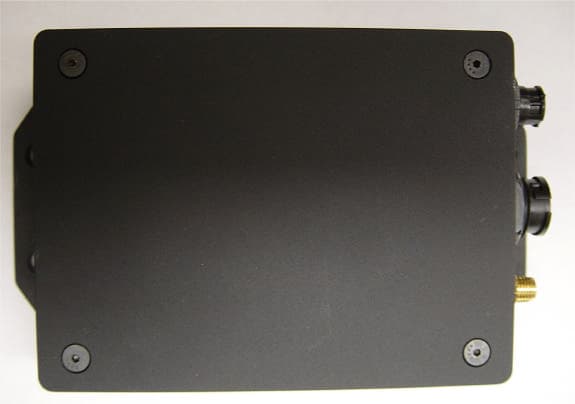
External Photos – For external photos, please see Internal Photos exhibit type. Justification for External Photos being held confidential is included in the Cover Letters exhibit type.
Parts List/Tune Up Info
2.1033(c)(9) TUNE-UP PROCEDURE Output power is controlled by base station automatically. Comment [jh1]: Information from customer checklist.
RF Exposure Info
5473A Clouds Rest Road : Mariposa, CA 95338 : Phone 209-966-5420 : Fax 209-742-6133 Maximum Permissible Exposure Calculations Date of Report: March 04 th , 2004 Calculations prepared for: Coleman Technologies 20 N Orange Avenue Suite 300 Orlando FL Calculations prepared by: Matthew Pettersen 110 N. Olinda Place Brea, CA 9283 Model Number: 1XRTT Agent FCC Identification: QQZ1XRTT Agent Fundamental Operating Frequency: 824.04-848.97MHz, 1851.25 MHz- 1908.75 MHz Maximum Rated Output Power: 0.28Watts Measured Maximum Output Power: 0.31 watts (Antenna terminal, 824.04 MHz) 0.28 Watts (Antenna terminal, 1851.25 MHz) MPE limit in accordance with FCC part 1.1311, table 1 Limit for Maximum permissible exposure: (B) Limit for General population/uncontrolled Exposure. For frequency range of 300-1500 MHz , the MPE is f / 1500 (mW/cm 2 ) For frequency range of 1500-100,000 MHz , the MPE is 1 (mW/cm 2 ) Power Output DistancePowr Density Power Density LimitResult (Watts) (meter) (W/M2) (mW/cm2)(mW/cm2) 0.280.20.91350.09140.5577PASS 0.310.21.01140.10110.5577PASS 0.280.20.91350.09141.0000PASS Power Density (W/M 2 ) = (30 * P t * G) / (d 2 * Zo) P t = Power Delivered to the Antenna G = Antenna Gain d = Distance in meters Zo = Impedance of Free Space = 377 Ω Under normal operating conditions, the antenna is designed to maintain a separation distance of 20 cm from all persons. As can be seen from the MPE results, this device passes the limits specified in 1.1311 at a distance of 20 cm and at the rated output power of 0.28 Watts At measured output power at antenna terminal of 0.48 Watts and 0.55 watts, the EUT satisfies the requirement in both frequency ranges.
Test Report
Page 1 of 32 Report No.: FC04-020A ADDENDUM TO COLEMAN TECHNOLOGIES TEST REPORT FC04-020 FOR THE AVL/GPS DATA LOGGING WITH WIRELESS COMMUNICATION, 1XRTT AGENT FCC PART 22 & PART 24 COMPLIANCE DATE OF ISSUE: APRIL 20, 2004 PREPARED FOR: Coleman Technologies 20 N. Orange Avenue, Suite 300 Orlando, FL PREPARED BY: Mary Ellen Clayton CKC Laboratories, Inc. 5473A Clouds Rest Mariposa, CA 95338 P.O. No.:JET 2677 W.O. No.:81879 Date of test:March 4-5, 2004 Report No.: FC04-020A This report contains a total of 32 pages and may be reproduced in full only. Partial reproduction may only be done with the written consent of CKC Laboratories, Inc. The results in this report apply only to the items tested, as identified herein. Page 2 of 32 Report No.: FC04-020A TABLE OF CONTENTS Administrative Information..............................................................................................3 Summary of Results.........................................................................................................4 Conditions for Compliance..............................................................................................4 Approvals.........................................................................................................................4 Equipment Under Test (EUT) Description......................................................................5 Equipment Under Test.....................................................................................................5 Peripheral Devices............................................................................................................5 Temperature and Humidity During Testing.....................................................................6 FCC 2.1033(c)(3) User’s Manual.....................................................................................6 FCC 2.1033(c)(4) Type of Emissions..............................................................................6 FCC 2.1033(c)(5) Frequency Range................................................................................6 FCC 2.1033(c)(6) Operating Power.................................................................................6 FCC 2.1033(c)(7) Maximum Power Rating.....................................................................6 FCC 2.1033(c)(8) DC Voltages.......................................................................................6 FCC 2.1033(c)(9) Tune-Up Procedure.............................................................................6 FCC 2.1033(c)(10) Schematics and Circuitry Description..............................................6 FCC 2.1033(c)(11) Label and Placement.........................................................................6 FCC 2.1033(c)(12) Submittal Photos...............................................................................6 FCC 2.1033(c)(13) Modulation Information...................................................................6 FCC 2.1033(c)(14)/2.1046/22.913/24.232 - RF Power Output.......................................7 FCC 2.1033(c)(14)/2.1047(b)/22.917(a) - Audio Frequency Response..........................10 FCC 2.1033(c)(14)/2.1047(b)/22.915(a) - Modulation Limiting Response....................10 FCC 2.1033(c)(14)/2.1049(i) - Occupied Bandwidth......................................................10 FCC 22.917(c) Emissions Mask.......................................................................................13 FCC 2.1033(c)(14)/2.1051/2.1053/22.917(e) - Out of Band Emissions..........................16 FCC 2.1033(c)(14)/2.1051/24.238 - Spurious Emissions at Antenna Terminal..............17 FCC 2.1033(c)(14)/2.1055/22.355/24.235 - Frequency Stability....................................22 FCC 24.236 - Field Strength Limits.................................................................................22 FCC Part 22 Block Edge..................................................................................................22 FCC Part 24 Block Edge..................................................................................................29 Page 3 of 32 Report No.: FC04-020A ADMINISTRATIVE INFORMATION DATE OF TEST:March 4-5, 2004 DATE OF RECEIPT:March 4, 2004 PURPOSE OF TEST:To demonstrate the compliance of the AVL/GPS Data Logging with Wireless Communication, 1XRTT Agent with the requirements for FCC Part 22 & Part 24 devices. Addendum A is to revise the operating power on page 6, add information regarding modulation and dc voltages, add a statement regarding conditions for compliance and revise the occupied bandwidth plots. TEST METHOD:FCC Part 22 & Part 24 FREQUENCY RANGE TESTED:9 kHz-20 GHz MANUFACTURER:Coleman Technologies 20 N. Orange Avenue, Suite 300 Orlando, FL REPRESENTATIVE:Peter Stern TEST LOCATION:CKC Laboratories, Inc. 110 Olinda Place Brea, CA 92621 Page 4 of 32 Report No.: FC04-020A SUMMARY OF RESULTS As received, the Coleman Technologies AVL/GPS Data Logging w/ Wireless Communication, 1XRTT Agent was found to be fully compliant with the following standards and specifications: United States ÿ FCC Part 22 & Part 24 CONDITIONS FOR COMPLIANCE Portions of testing contained in this test report represent a demonstration of continued compliance for this product. Emissions characteristics deemed unaffected by installation type are contained in a separate test report. APPROVALS Steve Behm, Director of Engineering Services QUALITY ASSURANCE:TEST PERSONNEL: Joyce Walker, Quality Assurance Administrative Manager Matthew Pettersen, EMC Test Engineer Page 5 of 32 Report No.: FC04-020A EQUIPMENT UNDER TEST (EUT) DESCRIPTION The EUT tested by CKC Laboratories was representative of a production unit. EQUIPMENT UNDER TEST AVL/GPS Data Logging with Wireless Communication Manuf: Coleman Technologies Model: 1XRTT Agent Serial: 20040304 FCC ID: QQZ (pending) PERIPHERAL DEVICES The EUT was tested with the following peripheral device(s): Laptop Manuf: Compaq Model: Evo N150 Seria…
Text truncated - open the document above for the full version.
Test Report
Page 1 of 78 Report No.: FC02-038A ADDENDUM TO FC02-038 FOR THE CDMA WIRELESS DATA MODEM, EMIII-DUAL FCC PART 22, PART 24 & PART 15 SUBPART B SECTIONS 15.107 AND 15.109 CLASS B COMPLIANCE DATE OF ISSUE: JUNE 26, 2002 PREPARED FOR: AnyDATA.NET, Incorporated Hanvit Bank Bldg. 7th Fl., 1-12 Byulyang-dong Kwachon City, Kyunggi-do, Korea, 427-040 PREPARED BY: Mary Ellen Clayton CKC Laboratories, Inc. 5473A Clouds Rest Mariposa, CA 95338 P.O. No.: ANY-0011 W.O. No.: 78691 Date of test:April 4 – May 7, 2002 Report No.: FC02-038A This report contains a total of 78 pages and may be reproduced in full only. Partial reproduction may only be done with the written consent of CKC Laboratories, Inc. The results in this report apply only to the items tested, as identified herein. Page 2 of 78 Report No.: FC02-038A TABLE OF CONTENTS Administrative Information ............................................................................................. 3 Summary of Results......................................................................................................... 4 Conditions for Compliance.............................................................................................. 4 Approvals......................................................................................................................... 4 Equipment Under Test (EUT) Description...................................................................... 5 Equipment Under Test..................................................................................................... 5 Peripheral Devices ........................................................................................................... 5 Temperature and Humidity During Testing .................................................................... 5 2.1033(c)(3) User’s Manual ............................................................................................ 6 2.1033(c)(4) Type of Emissions ...................................................................................... 6 2.1033(c)(5) Frequency Range ........................................................................................ 6 2.1033(c)(6) Operating Power ......................................................................................... 6 2.1033(c)(7) Maximum Power Rating............................................................................. 6 2.1033(c)(8) DC Voltages ............................................................................................... 6 2.1033(c)(9) Tune-Up Procedure .................................................................................... 6 2.1033(c)(10) Schematics and Circuitry Description ...................................................... 6 2.1033(c)(11) Label and Placement................................................................................. 6 2.1033(c)(12) Submittal Photos....................................................................................... 6 2.1033(c)(13) Modulation Information ........................................................................... 6 2.1033(c)(14)/2.1046/22.913/24.232(b) - RF Power Output........................................... 7 2.1033(c)(14)/2.1047(b) - Modulation - Audio Frequency Response............................. 12 2.1033(c)(14)/2.1047(b) - Modulation - Modulation Limiting Response ....................... 12 2.1033(c)(14)/2.1049(i) - Occupied Bandwidth .............................................................. 12 2.1033(c)(14)/2.1051/22.917(e)/24.238 - Spurious Emissions at Antenna Terminal ..... 17 2.1033(c)(14)/2.1053/22.917(e)/24.238 - Field Strength of Spurious Radiation ............ 30 2.1033(c)(14)/2.1055/22.355/24.235 - Frequency Stability ............................................ 39 2.1091 - Maximum Permissible Exposure Calculations ................................................. 41 15.107 – AC Conducted Emissions – Receiver/Digital .................................................. 42 15.109 – Radiated Emissions – Receiver/Digital ............................................................ 68 Page 3 of 78 Report No.: FC02-038A CKC Laboratories, Inc. has received Certificates of Accreditation from the following agencies: A2LA (USA); BSMI (Taiwan); Nemko (Norway); and GOST (Russia). CKC Laboratories, Inc has received test site Registration Acceptance from the following agencies: FCC (USA); VCCI (Japan); and Industry Canada. CKC Laboratories, Inc. has received Letters of Acceptance through an MRA for the following agencies: ACA/NATA (Australia); SABS (South Africa); SWEDAC (Sweden); Radio Communications Agency (RA); HOKLAS (Hong Kong); Bakom (Swiss); BIPT (Belgium); Denmark Telestyrelsen; RvA (Netherlands); SEE (Luxembourg) SITTEL (Bolivia); and UKAS (UK). ADMINISTRATIVE INFORMATION DATE OF TEST: April 4 – May 7, 2002 DATE OF RECEIPT: April 4, 2002 PURPOSE OF TEST: To demonstrate the compliance of the CDMA Wireless Data Modem, EMIII-Dual with the requirements for FCC Part 22, Part 24 & Part 15 Subpart B Sections 15.107 and 15.109 Class B devices. The purpose of addendum A is to revise the spurious radiation data sheets and clarify frequency stability information. TEST METHOD: FCC Part 22, Part 24 & ANSI C63.4 (1992) FREQUENCY RANGE TESTED: 9 kHz - 20 GHz MANUFACTURER: AnyDATA.NET, Incorporated Hanvit Bank Bldg. 7th Fl., 1-12 Byulyang-dong Kwachon City, Kyunggi-do, Korea, 427-040 REPRESENTATIVE: John Kim TEST LOCATION: CKC Laboratories, Inc. 110 Olinda Place, Brea, CA 92621 5473A Clouds Rest, Mariposa, CA 95338 Page 4 of 78 Report No.: FC02-038A SUMMARY OF RESULTS As received, the AnyDATA.NET, Incorporated CDMA Wireless Data Modem, EMIII-Dual was found to be fully compliant with the following standards and specifications: United States ! FCC Part 22, Part 24 & Part 15 Subpart B Sections 15.107 and 15.109 Class B ! FCC Part 22, Part 24 & ANSI C63.4 (1992) method CONDITIONS FOR COMPLIANCE Note: Enhanced grounding integrity by bonding the CDMA modem …
Text truncated - open the document above for the full version.
Test Setup Photos
TEST SETUP FCC 24.232 & 22.913 TEST SETUP FCC 24.232 & 22.913 PHOTOGRAPH SHOWING DIRECT CONNECT TEST SETUP Front View PHOTOGRAPH SHOWING DIRECT CONNECT TEST SETUP Side View
Contact Information
Applicant
James E Thomas(Director)
Technical Contact
CKC Laboratories, Inc.Mary Ellen Clayton
[email protected]209-966-5240
5473A Clouds Rest · Mariposa, California · United States
Non-Technical Contact
CKC Laboratories, Inc.Mary Ellen Clayton
[email protected]209-966-5240
Test Firm
CKC Laboratories, Inc.Steve Behm
Technical Specifications
| # | Rule Parts | Frequency Range | Power Output | Emission | Tolerance |
|---|---|---|---|---|---|
| 2 | 24E | 1.85 GHz - 1.91 GHz | 280.00 mW | 1M25F9W | 37.234 ppm |
Other Applications from Coleman Technologies, Inc.
QQZCDMA2000AGENT
Jan 23, 2003Vehicle Mounted Tracking System
Equipment Class
PCB - PCS Licensed Transmitter