QRTS-0501Printer
TOSHIBA TEC Singapore Pte Ltd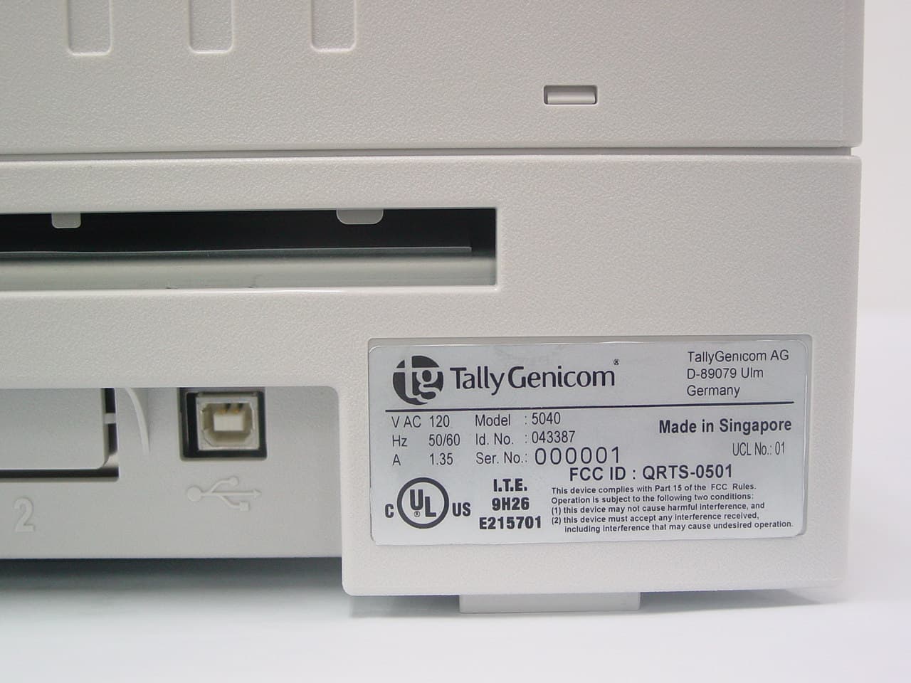
Click to zoom
Application Details
- Equipment Class
- JBP - Part 15 Class B Computing Device Peripheral
- Date of Grant
- Jan 26, 2006
- Application Purpose
- Original Equipment
- Date of Application
- Jan 26, 2006
- Equipment Note
- Printer
- Country
- Singapore
Documents & Files
Document Text
Text extracted from the exhibit documents filed with the FCC. Open a document above to read the original.
Users Manual
USER S E T U P 1 2 EJECT STOP 5040 Quick Start GuideFlatbed Printer This device fulfils the European standards requirements by complying with the Directive of the Commission dated May 3, 1989 (89/336/EEC) relating to electromagnetic compatibility and the Directive dated February 19, 1973 (73/23/EEC) relating to low-voltage electrical equipment. Conformity with the above mentioned Directives is indicated by the CE symbol attached to the device.Note: Conformity may be affected by: ■ using interface cables not co mplying with the specifications ■ non-observance of important instructions in the operator's manual ■ installing components not approved for this device by the manufacturer ■ unauthorized manipulation Cet appareil remplit aux exigences des normes européennes en respectant la directive du Conseil du 3 mai 1989 (89/336/CE) relative à la compatibilité électromagnétique et la direc-tive du 19février 1973 (73/23/CE) en matière du matériel à basse tension. La conformité aux directives mentionnées ci-dessus est repérée par la marque de conformité de la Com- munauté Européenne (CE).Remarque: La conformité peut être influencée par: ■ l'utilisation de câbles d'interface non spécifiés ■ le non-respect de consignes importantes du manuel d'utilisation ■ le remplacement de composants qui n'ont pas été homologués pour cet appareil par le constructeur ■ l'intervention de personnes non autorisées Important InformationThis equipment generates and uses radio frequency energy and if not installed and used properly, that is, in accordance with the manufacturer's instructions, may cause interference in radio and television reception. It has been type tested and found to comply with the limits for class B computing devices in accordance with the specification in subpart J of part 15 of FCC rules, which are designed to provide reasonable protection against such interference in a residential installation. However, there is no guarantee that interference will not occur in a partial installation. If this equipment does cause interference to radio or television reception, which can be determined by turning the equipment off and on, the user is encouraged to try to correct the interference by one or more of the following measures: ■ Reorient the receiving antenna, ■ Relocate the peripheral away from the receiver, ■ Move the peripheral away from the receiver ■ Plug the peripheral into a different outlet, so that the peri-pheral and receiver are on different branch circuits If necessary, the user should c onsult the dealer or an experi- enced radio/television technici an for additional suggestions. The user may find the following booklet, prepared by the Fe-deral Communications Commission, helpful: “How to Identify and Resolve Radio-TV Interference Problems”. This booklet is available from the U.S. Government Printing Of-fice, Washington DC 20402 Stock No. 004.000.00345.4.WARNING: To comply with FCC regulations on electromagne-tic interference for a class B computing device, the printer ca-ble must be shielded. To assure compliance with FCC regulations for a computing device, use a shielded interface cable with a metal shell connecto r. The use of cables not pro- perly shielded may result in violating FCC regulations.This digital apparatus does not exceed the class B limits for ra-dio noise emissions from digital apparatus as set out in the ra-dio interference regulations of the Canadian department of communications.This unit complies with DOC standard C108.8-M 1983ATTENTION: Le présent appareil numérique n'ement pas de bruits radioélectriques déspassan t les limites applicables aux appareils numériques de la classe B prescrites dans le règle- ment sur le brouillage radio-électrique édicté par le minstère des communications du Canada. WARNING For continued protection against ri sk of fire, replace only with same type and rating of fuse. Only trained and qualified personnel may open covers or remove parts that are not explicitly shown and described in the User Gu ide as being accessible to the operator. ATTENTION Pour ne pas compromettre la protection contre les risques d'ince ndie, remplacer par un fusible de même type et de mêmes carac- tèristiques nominales.Seul un personnel qualifié et formé est habili té à démonter les sous-ensembles de la ma chine qui ne sont pas formellement indi- qués dans le Manuel d'utilisation meme s' ils sont accessibles par l'opérateur. The paper used is made of raw materials treated with a chlorine-free bleaching process.Le papier utilisé est fabriqué à partir de matières premières blanchis sans chlore. Quick start guide Table of contents I ENGLISH Table of contentsIntroduction . . . . . . . . . . . . . . . . . . . . . . . . . . . . . . . 1 Symbols used. . . . . . . . . . . . . . . . . . . . . . . . . . . 1Important safety instructions . . . . . . . . . . . . . . . 1Using the Online CD-ROM. . . . . . . . . . . . . . . . . 2Contents of the Online CD-ROM . . . . . . . . . . . . 2Hardware requirements . . . . . . . . . . . . . . . . . . . 2Troubleshooting . . . . . . . . . . . . . . . . . . . . . . . . . 2 Printer at a glance . . . . . . . . . . . . . . . . . . . . . . . . . . 3 Installation . . . . . . . . . . . . . . . . . . . . . . . . . . . . . . . . 5 Unpacking the printer . . . . . . . . . . . . . . . . . . . . . 5Placing the printer . . . . . . . . . . . . . . . . . . . . . . . 6Checking the printer voltage . . . . . . . . . . . . . . . 7Connecting the printer . . . . . . . . . . . . . . . . . . . . 7Switching on the printer . . . . . . . . . . . . . . . . . . . 8 Control panel . . . . . . . . . . . . . . . . . . . . . . . . . . . . . . 9 Operating the printer . . . . . . . . . . . . . . . . . . . . . . . 10 Inserting a document . . . . . . . . . . . . . . . . . . . . 10Inserting a passbook . . . . . . . . . . . . . . . . . . . . 11 Service and Maintenance . . . . . . . . . . . . . . . . . . . 14 Replacing the ribbon cassette . . . . . . . . . . . . . 14Printing the Status Page …
Text truncated - open the document above for the full version.
Users Manual
Operating the printer Quick start guide 12 The bulge of the opened passbook should be as flat as possi-ble to avoid malfunctions when the passbook is drawn into the printer.Place the passbook on the right-hand side of the document support with the page to be printed facing up. Press the fold down while you push the passbook into the document chute towards the stop. Keep pushing it in until it is automatically pulled into the correct print position. If the automatic document alignment cannot properly grasp stiff or bent passbooks, you should place the passbook manually at the stop at the right-hand side of the document support and insert it. Quick start guide Operating the printer 13 ENGLISH When the passbook is inserted, the message ONLINE PAPER is displayed on the LCD. Do not use passbooks that do not correspond to the specifications listed in th e section “Paper specifica- tions”. Otherwise the passbooks and the print head may be damaged. When the passbook is printed, it is automatically transported out of the printer and released for removal. If the passbook will not be transported automatically out of the printer you can eject it by pressing the EJECT key.The message ONLINE NO PAPER appears on the LCD again. STOP Service and Maintenance Quick start guide 14Service and Maintenance` Replacing the ribbon cassette Make sure that the printer is switched off before replacing the ribbon cassette.The print head may be hot if the printer has been printing for a long time. Wait until it cools down and you are no longer in danger of being burnt. Open the cover by gr asping it at the right and left-hand side and swing it upward until it clicks into position.Press the green release lever for the printing mechanism. This swings the printing mechanism backwards. STOP Quick start guide Service and Maintenance 15 ENGLISH Remove the colored ribbon guide from the print head by pull-ing it downwards.Raise the front end of the ri bbon cassette on both sides. Take the ribbon cassette out of the printer. Service and Maintenance Quick start guide 16 Take the new ribbon cassette from the packaging and lift the ribbon guide from the cassette. Remove the transportation lock which fixes the ribbon guide to the cassette.Insert the new ribbon cassette by hooking it into the rear slots of its mountings first.Push the front of the cassette into its mounting so that it clicks into position. Please do not press the cente r of the ribbon cassette as this will deform the ribbon cassette and will cause operation problem. Quick start guide Service and Maintenance 17 ENGLISH Pull the ribbon guide under the print head. Tighten the ribbon by turning the tension gear in the direction of the arrow.Press the ribbon guide onto the print head from underneath until you hear it click into place.Check if the ribbon is transported correctly by turning the tension gear in the direction of the arrow. Service and Maintenance Quick start guide 18 Close the main frame by pressi ng the colored section in the middle of the frame as shown a nd ensure both left and right hand sides of the frames are fully latched.Close the cover. The printer is now ready to operate and to be switched on again. We recommend to check the printer's operation after replacing the ribbon cassette by performing a print-out of the parameter settings (see section “Printing the Status Page” on page 19”). Quick start guide Service and Maintenance 19 ENGLISH ` Printing the Status Page The printer has a function that allows you to printout the current parameter settings. Power the printer off.Press and hold the EJECT key wh ile switching on the printer. The LCD displays Print StatusPage Load Paper . Release the EJECT key.Insert the paper in the printer. The LCD displays Print StatusPage Printing and the printout of the status page is carried out.The paper will be ejected once printing is complete. Service and Maintenance Quick start guide 20 While printing, you can use the STOP key to pause the print- ing and LCD will display Print StatusPage Stop . You can resume the printing by pressing the STOP key again.If EJECT key is pressed in the Pause state, paper will be ejected and a reset will be performed.When the test printout is aborted or completed, LCD will dis-play Print StatusPage Completed . The Print setting mode will be ended automatically and a Power ON reset will be performed. Quick start guide Technical data 21 ENGLISH Technical data` Printer specifications For more information on printer specifications as well as interface specifications, refer to the User guide on the Online CD-ROM. Printing method 24-pin Dot matrix impact printer Character pitch 10; 12; 15; 17; 20; 24 characters/inch and proportional type (emulation-dependent) Line spacing Optional in microsteps n/60 inches n = 0 to 127 n/180 inches n = 0 to 255 n/360 inches n = 0 to 255 Print width 1 94 characters/line at 10 cpi 112 characters/line at 12 cpi141 characters/line at 15 cpi Print speed LQ: 133 cps; DQ: 400 cps Interface serial (RS232C), parallel (compatible Mode, ECP), USB 2.0 (Full speed) Nominal voltage 120V ± 10%, 230V ± 10% Line frequency 50/60Hz ± 3% Network form For use in power distribution systems with neutral and protective earth conductors (TN) Rated current intake Operation (maximum): US: 1.30 A; EU: 0.59 AStandby US: 0.11 A; EU: 0.072 A Apparent power consumption Operation (maximum): US: 89.7 VA; EU: 93.6 VAStandby US: 8 8.8 VA; EU: 11.4 VA True output Operation (maximum): US: 70.0 W; EU: 73.0 WStandby US: 7 6.9 W; EU: 7 8.9 W Sound output level LWAd 7.1 dB in operation Sound pressure level LpAm 55 dB in operation Dimensions Height: 168 mm, Width: 378 mm, Depth: 280 mm Weight Standard = 9,10 kg, MSR-H = 9,95 kg Approvals DIN EN 60 950 / VDE 0805, TUV (EN 60950) / Certified CE Mark, UL 60950 3rd Edition / C-UL (CSA C22.2 No 60950-00) new reversion, IEC 60950-1, EN 55022 :1998 (Class B), EN 55024 :1998, FCC PT 15B : 2000 (Class B), EN61000-3-2 :2000, EN61000-3-3 :1995, Energy Star Techn…
Text truncated - open the document above for the full version.
Block Diagram
Power input Cable ASIC Zeppelin 5 Head EEPROM2KB HeadCont.MotorCont. Dot counter MT0[fA,fB,fC,fD] 4 ResetWD WD_RFSMNI_WD 5V Regulator5V->3.3V 3.3V IEEE1284 IFD[7:0]ACK,BUSY,PE,FAULT,SESTB,IPM,SELIN,ATFD DRQ1/INTP101DRQ2/INTP102DRQ3/INTP103 5MH CK49MHz INTP031 DRQ0/INTP100 CPUV850E/MA1 TxD0/RxD0TxD1/RxD1 RS232C_0RS232C_1 AN[7:2] CTS0/RTS0,DTR0/DSR0CTS1/RTS1,DTR1/DSR1 A[12:0] INTP030 CLKOUT INT_OPM1INT_OPM2 DRQ_HD DRQ_CAM DRQ_MSWDDRQ_IMD 4 8 48 HD_U[24:1],H D_L[24:1] CA Motor MT1[fA,fB,fC,fD] 4 CS_GARDLWR,UWRRST FD Motor MT2[fA,fB,fC,fD] 4 PL Motor MT3[fA,fB,fC,fD] 4 MS Motor IMG dataCont. MT4[fA,fB,fC,fD] 4 MT5[fA,fB,fC,fD] 4 40V Regulator40V->12V 12V IO Port 4 2 AN[1,0] Option Motor1Option Motor2 OP PANEL USE SELECT STOP LCD PANEL FROMProgram4 MB OPT FROM CG0 4 MB SDRAM 8 MB CS_PGMRDLWRRSTCS_CG0RDLWRRSTCS_SDSDCLK/CKESDRAS/CASL/UWRWE A[21:1]A[21:1]A[22,21, 12:1] USB IC ML80651 CS_USBRD,LWRINT_USB A[7:0] 48MHz RST Sensors 6 A[25:0] D[15:0] RD,LWR,UWR SDCLK/CK SDWE,SDRAS/CA CS[CG0,CG1,CG2] CS[PGM,SD] D[7:0] D[15:0]D[15:0]D[15:0] USB IP ICLC821033 D[7:0] SI_CISCLK_CIS ID[7:0] INT_IP DRQ_IP DACK_IP SH_IPCLK1_IPCLK2_IP CK24MHz A[11:1] D[15:0] MICRD[1,0] CIS IA2004-ME31A 2 MICR MS INTP120INTP121INTP122 TC_HD TC2/INTP112TC3/INTP113TC1/INTP111TC0/INTP110 INT_FDM TC_MSWD TC_IMD INT_PLM INT_MSM INT_STB INTP010INTP020 INT_MSRDINT_MICR DACK0DACK2DACK3 INT_USB DACK_HD DACK_MSWD DACK_IMD INT_1284 INTP123 SO2INTP130SI2/INTP131SCK2/INTP132 1234567890 MICR AMP MICRD[1,0] 3 INT_MICR MS AMPPWB INT_MSRD MSWD MSRD MSWENA MSRDLVL DACK1 DACK_CA CS[IP,GA,USB] OPT FROM CG1 4 MB CS_CG1RDLWRRST A[21:1] D[15:0] OPT FROM CG2 4 MB CS_CG2RDLWRRST A[21:1] RST INTP133 4 CTS0/RTS0,DTR/DSR0CTS1/RTS1,DTR1/DSR1OPT_IO[ 7 :0] P0[3:1],P12 4 Latch BUF_DIR CS_5 [CS,RD,LWR]_IP MSWCLK 12 8 CS_IP CS[2,3,4] CS[0,1] CS[5,6,7] INTP011 INT_IP IC IC IC IC MICR/SCN PWB Parallel Cable (IEEE1394) RS-232 CableRS-232 Cable (Option) (Option) (Option) HOST COMPUTER USB Cable Switch Mode Power Supply AC 230V (EU)AC 120V (US) 50/60 Hz 40V 5V
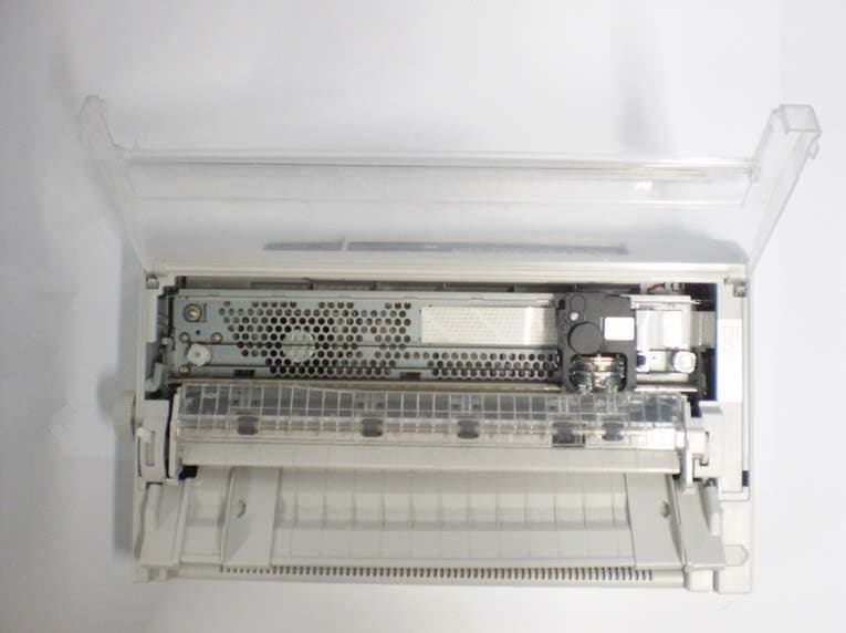
Internal Photos
PCB – Component Side
Internal Photos
PCB – Trace Side
Contact Information
Applicant
Lim Bee Lan(Engineer)
Test Firm
Toshiba TEC CorporationTetsuya Watanabe
Technical Specifications
| # | Rule Parts | Frequency Range | Power Output |
|---|---|---|---|
| 1 | 15B | - | - |
Other Applications from TOSHIBA TEC Singapore Pte Ltd
QRTS-0704
Dec 12, 2007Dot Matrix Printer
Equipment Class
JBP - Part 15 Class B Computing Device Peripheral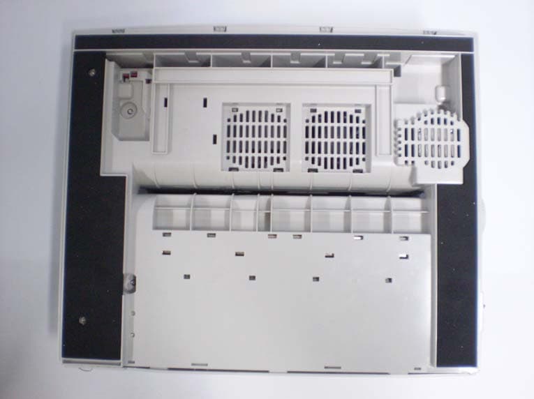
QRTS-0701
Dec 12, 2007Dot Matrix Printer
Equipment Class
JBP - Part 15 Class B Computing Device Peripheral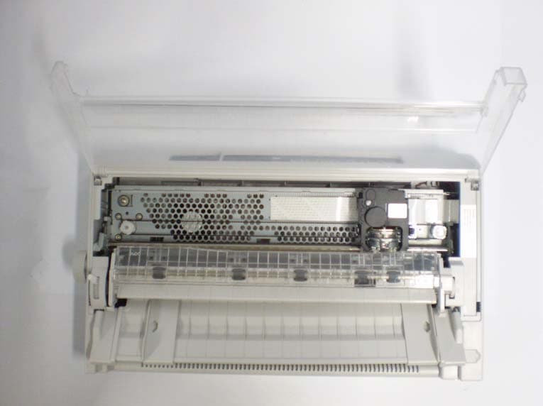
QRTS-0702
Dec 12, 2007Dot Matrix Printer
Equipment Class
JBP - Part 15 Class B Computing Device Peripheral
QRTS-0703
Dec 12, 2007Dot Matrix Printer
Equipment Class
JBP - Part 15 Class B Computing Device Peripheral
QRTS-0601
Apr 19, 2006Dot Printer
Equipment Class
JBP - Part 15 Class B Computing Device Peripheral