QSX57EC03LMG5.7GHz Fixed Wireless (U-NII)
Cascade Networks Inc.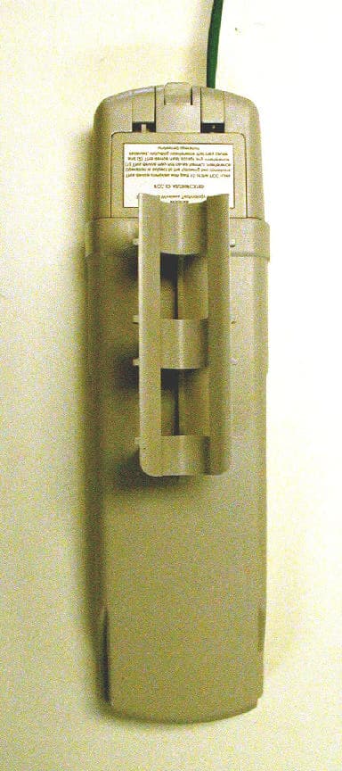
Click to zoom
Application Details
- Equipment Class
- NII - Unlicensed National Information Infrastructure TX
- Date of Grant
- Apr 08, 2003
- Application Purpose
- Original Equipment
- Date of Application
- Apr 07, 2003
- Equipment Note
- 5.7GHz Fixed Wireless (U-NII)
- Frequency Range
- 5745.00000000 - 5805.00000000
- Company
- Cascade Networks Inc.
- Country
- United States
Documents & Files
Document Text
Text extracted from the exhibit documents filed with the FCC. Open a document above to read the original.
Users Manual
Canopy Plus Backhaul Module USER MANUAL R 01. 01 NOTICES Federal Communications Commission (FCC) information: This device complies with part 15 of the FCC Rules and Regulations. Operation is subject to the following two conditions: (1) This device may not cause harmful interference, and (2) This device must accept any interference received, including interference that may cause undesired operation. This equipment has been tested and found to comply with the limits for a Class B digital device, pursuant to Part 15 of the FCC Rules. These limits are designed to provide reasonable protection against harmful interference in a residential installation. This equipment generates, uses, and can radiate radio-frequency energy and, if not installed and used in accordance with these instructions, may cause harmful interference to radio communications. If this equipment does cause harmful interference to radio or television reception, which can be determined by turning the equipment on and off, the user is encouraged to correct the interference by one or more of the following measures: Increase the separation between the affected equipment and the unit; Connect the affected equipment to a power outlet on a different circuit from that which the receiver is connected to; Consult the dealer and/or experienced radio/TV technician for help. This device must be professionally installed. FCC ID: QSX57EC03LMG Technical specifications were met. Important Note: Intentional or unintentional changes or modifications must not be made unless under the express consent of the party responsible for compliance. Any such modifications could void the user’s authority to operate the equipment and will void the manufacturer’s warranty. The Canopy Plus Backhaul (BH) must be installed to provide a separation distance of at least 20 cm (7.9 in) from all persons. Last Mile Gear P. O. Box 887 1324 Vandercook Way Longview, WA. 98632 www.lastmilegear.com Page 2 GETTING STARTED WELCOME Thank you for your purchase of a Canopy Plus access point. This new technology is the latest innovation in high speed wireless networking. Some of the Canopy Plus system features are: - Network speeds of 10/100 BaseT - Small compact design - No special set up on your PC. INTENDED USE This manual is intended to be used with Canopy Plus software release version 3.x or greater. The intended audience for this manual is system operators and equipment installers. WARRANTY Last Mile Gear offers a warranty covering a period of 90 days from the date of purchase by the customer. If a product is found defective during the warranty period, Last Mile Gear will repair or replace the product with the same or a similar model, which may be a reconditioned unit, without charge for parts or labor. IN NO EVENT SHALL LAST MILE GEAR BE LIABLE TO YOU OR ANY OTHER PARTY FOR ANY DIRECT, INDIRECT, GENERAL, SPECIAL, INCIDENTAL, CONSEQUENTIAL, EXEMPLARY OR OTHER DAMAGE ARISING OUT OF THE USE OR INABILITY TO USE THE PRODUCT (INCLUDING, WITHOUT LIMITATION, DAMAGES FOR LOSS OF BUSINESS PROFITS, BUSINESS INTERRUPTION, LOSS OF BUSINESS INFORMATION OR ANY OTHER PECUNIARY LOSS, OR FROM ANY BREACH OF WARRANTY, EVEN IF LAST MILE GEAR HAS BEEN ADVISED OF THE POSSIBILITY OF SUCH DAMAGES. (Some states do not allow the exclusion or limitation of incidental or consequential damages, so the above exclusion or limitation may not apply to you.) IN NO CASE SHALL LAST MILE GEAR LIABILITY EXCEED THE AMOUNT YOU PAID FOR THE PRODUCT. Page 3 BACKGROUND INFORMATION ON NETWORKING Computers are assigned IP addresses by network operators, which have two methods available, static or dynamic IP addressing. The user of this document will need to understand how IP addressing is done at their particular location. All Canopy radio products (Subscriber Modules, Access Point Modules, and Backhaul Modules) have the default IP address of 169.254.1.1. For a computer to talk to Canopy, as it comes from the factory, either of the following conditions must be met: If the computer is not configured for DHCP, then it has to have a static IP address on the 169.254 network (i.e. 169.254.1.5) If the computer is configured for DHCP, then it will automatically obtain an IP address on the 169.254 network after minute or two as long as it is not connected to the network. SITE SELECTION CRITERIA There are various issues that need to be taken into consideration when choosing a location for the network infrastructure. The following is a list of those considerations. There may be others as each site is unique. Height is essential when installing a Canopy backhaul module. The Canopy backhaul module must be mounted higher than other objects located immediately around it such as trees, buildings, tower legs, etc. There should be no obstructions that will interfere with the unit’s internal antenna. The area immediately in front of an access point module must be clear of all obstructions. Will the installation area change in the future? Will there be structures high enough to interfere with the signal? Will trees grow into the line-of-sight path? When possible, avoid high RF energy sites. Do not place Canopy equipment in the same plane as other RF equipment. The means used by the installer to attach the backhaul module to the tower, rooftop, or pole should be rigid and should not move or flex due to wind or other vibrations. Tower availability...will a tower have to erected? There must be grounding systems available for protection of the Canopy equipment. Lighting arrestors are required in installation areas to transport lightning strikes away from equipment. GENERAL CONSIDERATIONS Fresnel Loss - The Fresnel Zone is a theoretical area around the line of sight of an antenna transmission that can affect the signal strength. Objects that penetrate the Fresnel Zone can cause fading of the transmitted signal. This fading is caused by the cancellation of the signal due to out-of-phase reflections. An unobstruct…
Text truncated - open the document above for the full version.
Cover Letter(s)
April 10, 2003 FCC ID: QSX57EC03LMG Authorization & Evaluation Division Federal Communications Commission Laboratory 7435 Oakland Mills Road Columbia, MD 21046 Subject: Certification of Transmitter FCC ID: QSX57EC03LMG. Elite has granted a Cascade Networks FCC ID: QSX57EC03LMG. The Cascade Networks UNII system utilizes a previously granted Motorola transmitter FCC ID: ABZ89FC4816. The Cascade Networks system uses the identical Motorola transmitter with four external antennas listed on the grant. With the permission of Motorola, Elite used the original block diagrams, schematics, theory of operation, and test report for this submission. Elite will be happy to answer any questions or concerns you might have with this grant of certification. Please contact Daniel Crowder by telephone or e-mail at the following numbers: Telephone: (630) 495-9770 Ext. 101 E-mail: [email protected] Sincerely, Daniel E. Crowder Certification Department Coordinator ELITE ELECTRONIC ENGINEERING
Cover Letter(s)
FCC ID: [QSX57EC03LMG] Request for Confidentiality In accordance with 47 C.F.R. Section 0.459, we, (Cascade Networks, Inc.), hereby request confidentiality for the [block diagram, schematic and product description] presented for certification. In support of the Request for Confidentiality, the following is stated: Enclosed within this application is technical information which we deem to be trade secrets and proprietary. If made public, the information might be used to our disadvantage. To assist in assuring that we receive the full value of our product and protect its competitive posture, we respectfully request this grant of confidentiality. [Brian Magnuson] [Cascade Networks, Inc.]
ID Label/Location Info
Cyclone FCC ID: QSX57EC03LMG Model # 5700EC (1)This device may not cause harmful interference and (2) This device must accept any interference that may cause undesired operation.
Internal Photos
WHISP unit #170 Component Side: WHISP Unit #170, Solder Side: 27 WHISP unit #440 Component Side: 28 WHISP Unit #440, Solder Side:
RF Exposure Info
Motorola FCC ID: ABZ89FC4816 The Motorola Canopy device requesting certification is excluded from RF exposure because it is a fixed transmitter mounted on outdoor permanent structures and satisfies the MPE requirements of 2.1091 because of its low power.
Test Report
1 Canopy 5700 Conducted Test 16 December 2001 Compliance testing with FCC rules part 15.407 was performed in both conducted and radiated tests. The power spectral density measurement was setup on WHISP unit serial #440 before an antenna was added. The radio was connected to an HP (Agilent) 8596E Spectrum analyzer. Measurements were taken in 0Hz span with the spectrum analyzer synchronized to the transmitter’s data burst. This allowed the analyzer to make time gated power measurements of the radio. The test setup diagram is as follows: Silent carrier signal from the radio under test was used to calibrate the spectrum analyzer through the adjustable attenuator for a carrier power of 0 dBm. TX bit error test pattern was initiated to maximize the transmit duty cycle and data throughput for the radio under test. A testing program on the PC computer collected the 0Hz span power sweeps over a 60MHz frequency band. Post processing integrated the power measurements into the 1MHz measurement bandwidths for the plotted power spectral density. The data was offset via the radiated carrier power measurement (+29.05dBm) and plotted as shown. IBM PC Radio Under Test Ethernet Connection Spectrum Analyzer Oscilloscope Burst Trigger GPIB RF Cable RF Cable Adjustable Attenuator 2 The plot shown above indicates the worst case results for the radio operation in the frequency band 5725-5825MHz. The results show that at the carrier frequency the maximum power in a 1MHz BW is +16.05dBm radiated. In the region +/-25 to 26MHz the maximum amplitude was –48.45dBm or 31.4dB better than the maximum bandedge power of -17dBm radiated. In the region +/-20 to 21MHz the maximum amplitude was –34.25dBm or 17.2dB better than the maximum bandedge power of -17dBm radiated. Signals > +/-31MHz were below the measurement noise floor. From these measurements it can be seen that the WHiSP radio #440 passses the FCC part 15 specifications. 3 Canopy 5700 Radiated Test 16 December 2001 A Canopy 5700 unit, serial #440, was tested outdoors to check compliance with FCC requirement 15.209, restricted band emissions. The testing was done using a model 3115 and a model 3116 calibrated dual-ridged waveguide-horn antennas manufactured by EMCO, Inc., an Agilent 8564EC 40GHz spectrum analyzer, and a laptop to control the DUT and take data from the spectrum analyzer. The two antennas combined allowed a frequency measurement range of 1GHz to 40GHz. The spatial separation between the EMCO horn antennas and the DUT was maintained at 1 or 3 meters during the test. The FCC requirement for restricted band emissions is stated in terms of field strength at 500uV/m at a distance of 3 meters. Using the free space impedance of 377 ohms, the equivalent power density is –61.78dBm/m 2 . This power density number was used as the pass/fail criteria for the test. Cable losses, antenna gains, and other correction factors were entered into an Excel spreadsheet along with the results of the testing. To calculate the power density at the horn antennas, the power level received by the antenna is offset by the log ratio of the effective aperture of the antenna to one square meter. The calculation of the effective aperture is done using: A em = e cd (? 2 /4p)D o, D o is the directivity of the antenna, e cd is the efficiency, and ? is the wavelength of the frequency under observation. In the equation, e cd and D o may be replaced by the numeric gain of the antenna. Using the calibration data from the manufacturer, the effective area of the antenna was computed for each measurement frequency and the appropriate dB correction factor applied. The operating frequency of the radio presented a challenge to measuring the harmonics radiated by the radio. Since the highest harmonic to be measured is 34GHz (as the seventh harmonic exceeded the FCC frequency limit of 40GHz, it was not measured), finding test equipment that possess reasonable noise figures and obtaining coax cables with mode-free moderate loss is difficult. The resolution bandwidth of 1MHz also adds to the problem of making an effective radiated power measurement. As an aid in performing these measurements, the radio was designed with the ability to operate in continuous-wave mode (a proprietary mode of operation not available to the normal user), permitting the use of narrow bandwidths on the analyzer. In normal operation, logic in the radio will prevent the transmitter from operating in case of frequency error, and the resident firmware and hardware logic prevent transmissions when there is no data to be sent. 4 The picture below shows the configuration of the test set-up: 5 The test antennas and test radio were mounted on adjustable tripods and placed 1 or 3 meters apart, depending on the measurement antenna type. Absorbing panels were placed on the ground to reduce the effects of ground reflections. The test setup diagram is as follows: Two different antennas were used, an EMCO model 3115 ridged-waveguide horn antenna covering the 1 to 18GHz frequency range, and an EMCO model 3116 ridged- waveguide horn antenna covering the 18 to 40GHz frequency range. The radio has a CW mode for testing purposes and was used to measure the harmonic levels radiated from the radio. With no modulation, the measurement bandwidth could be reduced below 1MHz, allowing greater dynamic range for the test equipment. Measurements were made using a 30 kHz resolution bandwidth and a 1MHz bandwidth. Data used for calculations was taken from the 1MHz RBW measurements. Where no clearly discernable signal could be seen, the magnitude difference between signal and noise was set equal to a minimum value to avoid computational errors in the spreadsheet. Harmonic level as a function of channel frequency was reviewed and the RF channel possessing the highest harmonic level was used. Where harmonic levels were not strongly tied to the channel frequency, a nominal frequency of 5800MHz was used. Data from the analyzer was transferred to the laptop co…
Text truncated - open the document above for the full version.
Contact Information
Applicant
Brian E Magnuson(President)
Test Firm
Elite Electronic Engineering Co.Daniel Crowder
Technical Specifications
| # | Rule Parts | Frequency Range | Power Output | Tolerance |
|---|---|---|---|---|
| 1 | 15E | 5.75 GHz - 5.80 GHz | 200.00 mW | 25.0000000000 ppm |
Other Applications from Cascade Networks Inc.
QSX5700OFDM
Jan 06, 2011Cyclone
Equipment Class
DTS - Digital Transmission System
QSX900ISM
Aug 12, 2004Cyclone 900-360.7H
Equipment Class
DTS - Digital Transmission System
QSX2400ISM
Feb 16, 2004Cyclone Plus Broadband Wireless Transmitter
Equipment Class
DTS - Digital Transmission System
QSX5200UNII
Jul 31, 2003Cyclone Plus Broadband Wireless Transmitter
Equipment Class
NII - Unlicensed National Information Infrastructure TX
QSX5700ISM
Jul 31, 2003Cyclone Plus Broadband Wireless Transmitter
Equipment Class
DTS - Digital Transmission System