QUZ126728Personal ID Credential Field Distrubance Sensor
EG&G Technical Services, Inc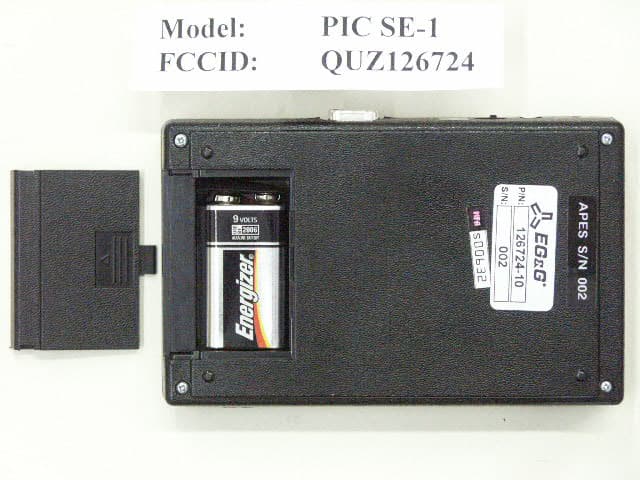
Click to zoom
Application Details
- Equipment Class
- FDS - Part 15 Field Disturbance Sensor
- Date of Grant
- Jun 22, 2003
- Application Purpose
- Original Equipment
- Date of Application
- Mar 18, 2003
- Equipment Note
- Personal ID Credential Field Distrubance Sensor
- Frequency Range
- 916.48000000 - 916.48000000
- Company
- EG&G Technical Services, Inc
- Country
- United States
Documents & Files
Document Text
Text extracted from the exhibit documents filed with the FCC. Open a document above to read the original.
Users Manual
PICS POC User’s Manual 13 January 2003 PERSONAL IDENTIFICATION CREDENTIAL SYSTEM (PICS) PROOF OF CONCEPT (POC) USER’S MANUAL Contract No. GS23F0108J Delivery Order No. F19628-02-F-0048 13 January 2003 Prepared for Electronic Systems Center ESC/FD 5 Eglin Street Hanscom AFB, MA 01731-2100 DISTRIBUTION STATEMENT C: Distribution authorized to U.S. Government agencies and their contractors for Administrative and Operational Use, 4 April 2002. Other requests for this document shall be referred to ESC/FDP, 5 Eglin Street, Bldg. 1624, Prepared by EG&G Technical Services, Inc. Albuquerque Operations 2420 Comanche, NE Suite D-2 Albuquerque, NM 87107 CAGE Code 29674 1 PICS POC User’s Manual 13 January 2003 1.0 SCOPE This document is intended to provide guidance to the end user of the Personal Identification Credential System (PICS) for normal operations. It is intended to cover only the Proof of Concept iteration of the PICS. It describes typical operation of the Personal Identification Credential (PIC), the PICS Enrollment Station, and the PICS Reader. In general, the roles discussed within this document cover the PIC user, the PICS Enrollment Station operator, and the PICS maintainer. The PIC user need only be concerned with the operation of the PIC itself. The PICS Enrollment Station operator will need to be familiar with both the PIC operation and the PICS Enrollment Station operation. The PICS maintainer will need to be familiar with all three roles. 1.1 Glossary PIC Personal Identification Credential (handheld identification unit incorporating biometric sensor and RF link) PICS Personal Identification Credential System PICS Enrollment Station Enrollment subsystem that assigns a PIC to an individual and maintains the database PICS Reader Interrogation unit that communicates with the PIC and is interfaced with a local access control system Proof of Concept (POC) PICS prototype PICS that closely resembles the production system PIC User(s) The PIC Users are the end users of the system. The PIC users will be assigned a PIC and be enrolled in the PICS. The PIC users will interact only with the PIC to which they have been assigned Enrollment Station Operator The Enrollment Station Operator uses the Enrollment Station on a regular basis to enroll and disenroll PIC users. PICS Maintainer The PICS Maintainer is responsible for system configuration operations and troubleshooting problems which may arise. This includes setting up/configuring the PICS Reader, setting up, configuring and maintaining the PICS Enrollment Station and its software, including the PICS Enrollment Station software and its associated database. The PICS Maintainer roll may be accomplished by more than one individual. 2 PICS POC User’s Manual 13 January 2003 1.2 Documentation Conventions Screen Labels Represents labels that appear on the screen in the PICS Manager software. Database Field Names Represents fields in the PICS database. User Entered Data Represents data which the user must enter. File Contents Represents the listing of files used by the system. 3 PICS POC User’s Manual 13 January 2003 2.0 REFERENCE DOCUMENTS EG&G Drawing 126764-10, PICS Installation EG&G Drawing 126762-10, Assy, PICS Reader Terminal Unit 4 PICS POC User’s Manual 13 January 2003 3.0 DESCRIPTIONS The Personal Identification Credential System (PICS) is intended to provide access control using a Personal Identification Credential (PIC), which can be issued to individual users. The PIC will be a small, handheld, wireless biometric device small enough to fit in a shirt pocket. In the initial application, users will operate the PIC from within a vehicle in order to gain access to a facility. In addition to the PIC, the system will include a PICS Enrollment Station, which consists of a MS Windows based PC software application with an RF interface attached to a serial port. The Enrollment Station software will run under the MS Windows environment and provide enrollment capability and enrollment database maintenance. Lastly, the PICS Reader is used to control access of users to the system. The PICS Reader provides interrogation of PIC units and validation of PIC enrollment. The PIC is responsible for validating the fingerprint, but the Reader is responsible for insuring that a given PIC is to be allowed in the system. 3.1 PIC Operation The operation of the PIC is straightforward, but the nature of the biometric fingerprint sensor is such that the user will need to become well practiced in using it. The guidelines given here may not work for everyone. Some users may find that a different approach to using the sensor will yield better results. Unfortunately, the typical user will have little time to experiment with using the PIC before being permanently enrolled in it. The PIC automatically turns itself off after approximately 5 to 10 seconds. The act of sliding open the fingerprint sensor activates the electronics inside. The PIC will emit a short high pitch beep and briefly flash the LED yellow to indicate that it is alive. If the batteries are getting low, the PIC will emit three short low pitch beeps and briefly flash the LED red. If the batteries are too low, the PIC may not have enough power to function correctly. The batteries should be replaced immediately upon receiving a low battery indication. Once the PIC is turned on, it will immediately start scanning for a valid fingerprint. It is important for the user to be consistent in applying the finger to be tested. In order to facilitate the correct application of the fingertip, the user should place the fingertip in the indented portion of the slide cover, then slide the cover open and place the flat part of the fingertip on the sensor. Figure 1 shows correct and incorrect placements of the fingertip on the sensor. 5 PICS POC User’s Manual 13 January 2003 Correct Incorrect Figure 1 PIC Fingertip Placement Once the finger is placed on the sensor, the LED should light indicating the status of the verificatio…
Text truncated - open the document above for the full version.
ID Label/Location Info
THIS DEVICECOMPLIES WITH PART 15 OF THE FCC RULES.OPERATION IS SUBJECT TO THE FOLLOWING TWO CONDITIONS:INCLUDING INTERFERENCE THAT MAY CAUSE UNDESIRED OPERATION.2) THIS DEVICE MUST ACCEPT ANY INTERFERENCE RECEIVED,1) THIS DEVICE MAY NOT CAUSE HARMFUL INTERFERENCE, AND FCC ID: QUZ126728EG&G TECHNICAL SERVICES INC. THIS DEVICECOMPLIES WITH PART 15 OF THE FCC RULES.OPERATION IS SUBJECT TO THE FOLLOWING TWO CONDITIONS:INCLUDING INTERFERENCE THAT MAY CAUSE UNDESIRED OPERATION.2) THIS DEVICE MUST ACCEPT ANY INTERFERENCE RECEIVED,1) THIS DEVICE MAY NOT CAUSE HARMFUL INTERFERENCE, AND FCC ID: QUZ126742EG&G TECHNICAL SERVICES INC. MODEL: PIC-1 MADE IN U.S.A. MODEL: PICSR-1 MADE IN U.S.A. COMPANY PROPRIETARY EG&G TECHNICAL SERVICES INC.FCC ID: QUZ126724MODEL: PICSE-1 MADE IN U.S.A. THIS DEVICECOMPLIES WITH PART 15 OF THE FCC RULES.OPERATION IS SUBJECT TO THE FOLLOWING TWO CONDITIONS:1) THIS DEVICE MAY NOT CAUSE HARMFUL INTERFERENCE, AND2) THIS DEVICE MUST ACCEPT ANY INTERFERENCE RECEIVED,INCLUDING INTERFERENCE THAT MAY CAUSE UNDESIRED OPERATION.
Test Report
FCC ID: QUZ126728 Date: March 14, 2003 Federal Communications Commission Via: Electronic Filing Attention: Authorization & Evaluation Division Applicant: EG & G Technical Services, Inc. Equipment: PIC-1 FCC ID: QUZ126728 FCC Rules: 15.249, Confidentiality Gentlemen: On behalf of the Applicant, enclosed please find Application Form 731, Engineering Test Report and all pertinent documentation, the whole for approval of the referenced equipment as shown. Filing fees are attached. We trust the same is in order. Should you need any further information, kindly contact the writer who is authorized to act as agent. Sincerely yours, Morton Flom, P. Eng. enclosure(s) cc: Applicant MF/cva MFA p0330004, d0330036 FCC ID: QUZ126728 LIST OF EXHIBITS (FCC CERTIFICATION (TRANSMITTERS) - REVISED 9/28/98) APPLICANT: EG & G Technical Services, Inc. FCC ID: QUZ126728 BY APPLICANT: 1. LETTER OF AUTHORIZATION x 2. IDENTIFICATION DRAWINGS x LABEL x LOCATION OF LABEL x COMPLIANCE STATEMENT x LOCATION OF COMPLIANCE STATEMENT 3. DOCUMENTATION: 2.1033(b) (3) USER MANUAL x (4) OPERATIONAL DESCRIPTION x (5) BLOCK DIAGRAM x (5) SCHEMATIC DIAGRAM x (7) PHOTOGRAPHS x BLOCK DIAGRAM x PARTS LIST x 4. REQUEST FOR CONFIDENTIALITY x BY M.F.A. INC. A. TESTIMONIAL & STATEMENT OF CERTIFICATION B. STATEMENT OF QUALIFICATIONS MFA p0330004, d0330036 FCC ID: QUZ126728 T R A N S M I T T E R C E R T I F I C A T I O N of FCC ID: QUZ126728 MODEL: PIC-1 to FEDERAL COMMUNICATIONS COMMISSION Rule Part(s) 15.249, Confidentiality DATE OF REPORT: March 14, 2003 ON THE BEHALF OF THE APPLICANT: EG & G Technical Services, Inc. AT THE REQUEST OF : P.O. Part of A33201712 EG & G Technical Services, Inc. 2420 Comanche Rd., NE., STE D-2 Albuquerque, NM 87107 Attention of: Marie Stoffer (505) 998-0677 x 211; FAX: -0671 email: [email protected] SUPERVISED BY: Morton Flom, P. Eng. MFA p0330004, d0330036 FCC ID: QUZ126728 THE APPLICANT HAS BEEN CAUTIONED AS TO THE FOLLOWING: 15.21 INFORMATION TO USER. The users manual or instruction manual for an intentional radiator shall caution the user that changes or modifications not expressly approved by the party responsible for compliance could void the user's authority to operate the equipment. 15.27(a) SPECIAL ACCESSORIES. Equipment marketed to a consumer must be capable of complying with the necessary regulations in the configuration in which the equipment is marketed. Where special accessories, such as shielded cables and/or special connectors are required to enable an unintentional or intentional radiator to comply with the emission limits in this part, the equipment must be marketed with, i.e. shipped and sold with, those special accessories. However, in lieu of shipping or packaging the special accessories with the unintentional or intentional radiator, the responsible party may employ other methods of ensuring that the special accessories are provided to the consumer, without additional charge. Information detailing any alternative method used to supply the special accessories for a grant of equipment authorization or retained in the verification records, as appropriate. The party responsible for the equipment, as detailed in § 2.909 of this chapter, shall ensure that these special accessories are provided with the equipment. The instruction manual for such devices shall include appropriate instructions on the first page of text concerned with the installation of the device that these special accessories must be used with the device. It is the responsibility of the user to use the needed special accessories supplied with the equipment. MFA p0330004, d0330036 FCC ID: QUZ126728 TABLE OF CONTENTS RULE DESCRIPTION PAGE . Test Report 1 2.1033(c) General Information Required 2 . Standard Test Conditions and Engineering Practices 6 2.1051 Unwanted Emissions (Transmitter Conducted) 7 2.1046(a) ERP Carrier Power (Radiated) 10 2.1053(a) Field Strength of Spurious Radiation 11 2.1049(c)(1) Emission Masks (Occupied Bandwidth) 16 MFA p0330004, d0330036 FCC ID: QUZ126728 PAGE NO. 1 of 21. Required information per ISO/IEC Guide 25-1990, paragraph 13.2: a) TEST REPORT b) Laboratory: (FCC: 31040/SIT) (Canada: IC 2044) M. Flom Associates, Inc. 3356 N. San Marcos Place, Suite 107 Chandler, AZ 85225 c) Report Number: d0330036 d) Client: EG & G Technical Services, Inc. 2420 Comanche Rd., NE., STE D-2 Albuquerque, NM 87107 e) Identification: PIC-1 FCC ID: QUZ126728 Description: Personal ID Credential System Reader f) EUT Condition: Not required unless specified in individual tests. g) Report Date: March 14, 2003 EUT Received: March 7, 2003 h, j, k): As indicated in individual tests. i) Sampling method: No sampling procedure used. l) Uncertainty: In accordance with MFA internal quality manual. m) Supervised by: Morton Flom, P. Eng. n) Results: The results presented in this report relate only to the item tested. o) Reproduction: This report must not be reproduced, except in full, without written permission from this laboratory. MFA p0330004, d0330036 FCC ID: QUZ126728 PAGE NO. 2 of 21. LIST OF GENERAL INFORMATION REQUIRED FOR CERTIFICATION IN ACCORDANCE WITH FCC RULES AND REGULATIONS, VOLUME II, PART 2 AND TO 15.249, Confidentiality Sub-part 2.1033 (c)(1): NAME AND ADDRESS OF APPLICANT: EG & G Technical Services, Inc. P.O. Box 9100 Albuquerque, NM 87119-9100 MANUFACTURER: Applicant (c)(2): FCC ID: QUZ126728 MODEL NO: PIC-1 (c)(3): INSTRUCTION MANUAL(S): PLEASE SEE ATTACHED EXHIBITS (c)(4): TYPE OF EMISSION: 182K0F2D (c)(5): FREQUENCY RANGE, MHz : 902 to 928 (c)(6): POWER RATING, Watts: 0.0005 to 0.004 Switchable x Variable N/A (c)(7): MAXIMUM POWER RATING, Watts : 50 mv/m @ 3m 15.203: ANTENNA REQUIREMENT: x The antenna is permanently attached to the EUT The antenna uses a unique coupling The EUT must be professionally installed The antenna requirement does not apply PLEASE NOTE: ALL DEVICES CONTAIN AN R.F. MODULE MANUFACTURED BY LINX TECHNOLOGIES, FCC ID: OJM-TR-916-SC. MFA p0330004, d0330036 FCC ID: QUZ126728 PAGE NO. 3 of …
Text truncated - open the document above for the full version.
Test Report
FCC ID: QUZ126728 PAGE NO. 14 of 21. AMENDED March 20, 2003 TEST SETUP: Radiated Emissions MFA p0330004, d0330036
Test Report
FCC ID: QUZ126728 T R A N S M I T T E R C E R T I F I C A T I O N of FCC ID: QUZ126728 MODEL: PIC-1 to FEDERAL COMMUNICATIONS COMMISSION Rule Part(s) 15.245, Confidentiality DATE OF REPORT: March 14, 2003 AMENDED: June 4, 2003 ON THE BEHALF OF THE APPLICANT: EG & G Technical Services, Inc. AT THE REQUEST OF : P.O. Part of A33201712 EG & G Technical Services, Inc. 2420 Comanche Rd., NE., STE D-2 Albuquerque, NM 87107 Attention of: Marie Stoffer (505) 998-0677 x 211; FAX: -0671 email: [email protected] SUPERVISED BY: Morton Flom, P. Eng. MFA p0330004, d0330036 FCC ID: QUZ126728 PAGE NO. 2 of 21. AMENDED June 4, 2003 LIST OF GENERAL INFORMATION REQUIRED FOR CERTIFICATION IN ACCORDANCE WITH FCC RULES AND REGULATIONS, VOLUME II, PART 2 AND TO 15.245, Confidentiality Sub-part 2.1033 (c)(1): NAME AND ADDRESS OF APPLICANT: EG & G Technical Services, Inc. P.O. Box 9100 Albuquerque, NM 87119-9100 MANUFACTURER: Applicant (c)(2): FCC ID: QUZ126728 MODEL NO: PIC-1 (c)(3): INSTRUCTION MANUAL(S): PLEASE SEE ATTACHED EXHIBITS (c)(4): TYPE OF EMISSION: 182K0F2D (c)(5): FREQUENCY RANGE, MHz : 902 to 928 (c)(6): POWER RATING, Watts: 0.0005 to 0.004 Switchable x Variable N/A (c)(7): MAXIMUM POWER RATING, Watts : 500 mv/m @ 3m 15.203: ANTENNA REQUIREMENT: x The antenna is permanently attached to the EUT The antenna uses a unique coupling The EUT must be professionally installed The antenna requirement does not apply PLEASE NOTE: ALL DEVICES CONTAIN AN R.F. MODULE MANUFACTURED BY LINX TECHNOLOGIES, FCC ID: OJM-TR-916-SC. MFA p0330004, d0330036 FCC ID: QUZ126728 PAGE NO. 5 of 21. AMENDED June 4, 2003 Sub-part 2.1033(b): TEST AND MEASUREMENT DATA All tests and measurement data shown were performed in accordance with FCC Rules and Regulations, Volume II; Part 2, Sub-part J, Sections 2.1031, 2.1033, 2.1035, 2.1041, 2.1043, 2.1045, and the following individual Parts: 15.209 Radiated emission limits; general requirements 15.211 Tunnel radio systems 15.213 Cable locating equipment 15.214 Cordless telephones 15.217 Operation in the band 160-190 kHz 15.219 Operation in the band 510-1705 kHz 15.221 Operation in the band 525-1705 kHz (leaky coax) 15.223 Operation in the band 1.705-10 MHz 15.225 Operation in the band 13.553-13.567 MHz 15.227 Operation in the band 26-27.28 MHz (remote control) 15.229 Operation in the band 40.66-40.70 MHz 15.231 Periodic operation in the band 40.66-40.70 MHz and above 70 MHz 15.233 Operation within the bands 43.71-44.49, 46.60-46.98 MHz 48.75-49.51 MHz and 49.66-50.0 MHz 15.235 Operation within the band 49.82-49.90 MHz 15.237 Operation within the bands 72.0-73.0 MHz, 74.6-74.8 MHz and 75.2-76.0 MHz (auditory assistance) 15.239 Operation in band 88-108 MHz 15.241 Operation in the band 174-216 MHz (biomedical) 15.243 Operation in the band 890-940 MHz (materials) x 15.245 Operation within the bands 902-928 MHz, 2435-2465 MHz, 5785-5815 MHz, 10500-10550 MHz, and 24075-24175 MHz (field disturbance sensors) 15.247 Operation within bands 902-928 MHz, 2400-2483.5 MHz, and 5725-5850 MHz (spread spectrum) 15.249 Operation within the bands 902-928 MHz, 2400-2483.5 MHz, 5725-5875 MHz, and 24.0-24.25 GHz 15.251 Operation within the bands 2.9-3.26 GHz, 3.267-3.332 GHz, 3.339-3.3458 GHz, and 3.358-3.6 GHz (vehicle identification systems) 15.321 Specific requirements for asynchronous devices operating in the 1910-1920 MHz and 2390-2400 MHz bands (Unlicensed PCS) 15.323 Specific requirements for isochronous devices operating in the 1920-1930 MHz sub-band (Unlicensed PCS) MFA p0330004, d0330036 FCC ID: QUZ126728 PAGE NO. 9 of 21. AMENDED June 4, 2003 NAME OF TEST: Unwanted Emissions (Transmitter Conducted) LIMIT, dBc -49, for 4.0 mw, maximum (450 mw) Actual = 1 mw g0330056: 2003-Mar-10 Mon 10:30:00 STATE: 2:High Power FREQUENCY TUNED, MHz FREQUENCY EMISSION, MHz LEVEL, dBm LEVEL, dBc 916.480000 1832.882700 -80.5 ≤-80.6 916.480000 2749.620100 -86.2 ≤-80.6 916.480000 3665.743400 -87.4 ≤-80.6 916.480000 4582.309700 -86.7 ≤-80.6 916.480000 5498.861500 -86.1 ≤-80.6 916.480000 6415.144400 -80.5 ≤-80.6 916.480000 7331.678300 -80.6 ≤-80.6 916.480000 8248.209200 -81.2 ≤-80.6 916.480000 9164.695700 -79.5 ≤-80.6 916.480000 10081.403300 -80.1 ≤-80.6 916.480000 10998.009500 -79.5 ≤-80.6 916.480000 11914.466000 -79.6 ≤-80.6 916.480000 12830.692100 -74.9 ≤-80.6 916.480000 13747.443500 -74.8 ≤-80.6 Morton Flom, P. Eng. MFA p0330004, d0330036 FCC ID: QUZ126728 PAGE NO. 10 of 21. AMENDED June 4, 2003 NAME OF TEST: ERP Carrier Power (Radiated) SPECIFICATION: TIA/EIA 603A (Substitution Method) 2.2.17.1 Definition: The average radiated power of a licensed device is the equivalent power required, when delivered to a half-wave dipole or horn antenna, to produce at a distant point the same average received power as produced by the licensed device. 2.2.17.2 Method of Measurement: a) Connect the equipment as illustrated. Place the transmitter to be tested on the turntable in the standard test site. b) Raise and lower the test antenna from 1m to 6 m with the transmitter facing the antenna and record the highest received signal in dB as LVL. c) Repeat step b) for seven additional readings at 45 ̊ interval positions of the turntable. d) Replace the transmitter under test with a half-wave or horn vertically polarized antenna. The center of the antenna should be at the same location as the transmitter under test. Connect the antenna to a signal generator with a known output power and record the path loss in dB or LOSS. e) Calculate the average radiated output power from the readings in step c) and d) by the following: average radiated power = 10 log 10 Σ 10(LVL – LOSS)/10 (dBm) RESULTS 916.48 MHZ LVL, dbm Path Loss, db 0 ̊ -26.8 1.8 45 ̊ -37.9 1.8 90 ̊ -4.2 1.8 135 ̊ -25.0 1.8 180 ̊ -29.0 1.8 225 ̊ -23.6 1.8 270 ̊ -30.2 1.8 315 ̊ -23.5 1.8 916.48 MHZ Av. Radiated Power: -26.83 dbm Worse case: -4.2 dbm = 140 millivolts MFA p0330004, d0330036 FCC ID: QUZ126728 PAGE NO. 15 of 21. AMENDED June 4, 2003 NAME OF TEST: Field Strength of Spurio…
Text truncated - open the document above for the full version.
Test Report
FCC ID: QUZ126728 PAGE NO. 2 of 21. AMENDED June 20, 2003 LIST OF GENERAL INFORMATION REQUIRED FOR CERTIFICATION IN ACCORDANCE WITH FCC RULES AND REGULATIONS, VOLUME II, PART 2 AND TO 15.245, Confidentiality Sub-part 2.1033 (c)(1): NAME AND ADDRESS OF APPLICANT: EG & G Technical Services, Inc. P.O. Box 9100 Albuquerque, NM 87119-9100 MANUFACTURER: Applicant (c)(2): FCC ID: QUZ126728 MODEL NO: PIC-1 (c)(3): INSTRUCTION MANUAL(S): PLEASE SEE ATTACHED EXHIBITS (c)(5): FREQUENCY RANGE, MHz: 902 to 928 (c)(6): POWER RATING, Watts : 0.0005 to 0.004 Switchable x Variable N/A (c)(7): MAXIMUM POWER RATING, Watts : 500 mv/m @ 3m 15.203: ANTENNA REQUIREMENT : x The antenna is permanently attached to the EUT The antenna uses a unique coupling The EUT must be professionally installed The antenna requirement does not apply PLEASE NOTE: ALL DEVICES CONTAIN AN R.F. MODULE MANUFACTURED BY LINX TECHNOLOGIES, FCC ID: OJM-TR-916-SC. MFA p0330004, d0330036 FCC ID: QUZ126728 PAGE NO. 5 of 21. AMENDED June 20, 2003 Sub-part 2.1033(b): TEST AND MEASUREMENT DATA All tests and measurement data shown were performed in accordance with FCC Rules and Regulations, Volume II; Part 2, Sub-part J, Sections 2.1031, 2.1033, 2.1035, 2.1041, 2.1043, 2.1045, and the following individual Parts: 15.209 Radiated emission limits; general requirements 15.211 Tunnel radio systems 15.213 Cable locating equipment 15.214 Cordless telephones 15.217 Operation in the band 160-190 kHz 15.219 Operation in the band 510-1705 kHz 15.221 Operation in the band 525-1705 kHz (leaky coax) 15.223 Operation in the band 1.705-10 MHz 15.225 Operation in the band 13.553-13.567 MHz 15.227 Operation in the band 26-27.28 MHz (remote control) 15.229 Operation in the band 40.66-40.70 MHz 15.231 Periodic operation in the band 40.66-40.70 MHz and above 70 MHz 15.233 Operation within the bands 43.71-44.49, 46.60-46.98 MHz 48.75-49.51 MHz and 49.66-50.0 MHz 15.235 Operation within the band 49.82-49.90 MHz 15.237 Operation within the bands 72.0-73.0 MHz, 74.6-74.8 MHz and 75.2-76.0 MHz (auditory assistance) 15.239 Operation in band 88-108 MHz 15.241 Operation in the band 174-216 MHz (biomedical) 15.243 Operation in the band 890-940 MHz (materials) x 15.245 Operation within the bands 902-928 MHz, 2435-2465 MHz, 5785-5815 MHz, 10500-10550 MHz, and 24075-24175 MHz (field disturbance sensors) 15.247 Operation within bands 902-928 MHz, 2400-2483.5 MHz, and 5725-5850 MHz (spread spectrum) 15.249 Operation within the bands 902-928 MHz, 2400-2483.5 MHz, 5725-5875 MHz, and 24.0-24.25 GHz 15.251 Operation within the bands 2.9-3.26 GHz, 3.267-3.332 GHz, 3.339-3.3458 GHz, and 3.358-3.6 GHz (vehicle identification systems) 15.321 Specific requirements for asynchronous devices operating in the 1910-1920 MHz and 2390-2400 MHz bands (Unlicensed PCS) 15.323 Specific requirements for isochronous devices operating in the 1920-1930 MHz sub-band (Unlicensed PCS) MFA p0330004, d0330036 FCC ID: QUZ126728 PAGE NO. 9 of 21. AMENDED June 20, 2003 NAME OF TEST: Unwanted Emissions (Transmitter Conducted) LIMIT, dBc -49, for 4.0 mw, maximum (450 mw) Actual = 1 mw g0330056: 2003-Mar-10 Mon 10:30:00 STATE: 2:High Power FREQUENCY TUNED, MHz FREQUENCY EMISSION, MHz LEVEL, dBm 916.480000 1832.882700 -80.5 916.480000 2749.620100 -86.2 916.480000 3665.743400 -87.4 916.480000 4582.309700 -86.7 916.480000 5498.861500 -86.1 916.480000 6415.144400 -80.5 916.480000 7331.678300 -80.6 916.480000 8248.209200 -81.2 916.480000 9164.695700 -79.5 916.480000 10081.403300 -80.1 916.480000 10998.009500 -79.5 916.480000 11914.466000 -79.6 916.480000 12830.692100 -74.9 916.480000 13747.443500 -74.8 Morton Flom, P. Eng. MFA p0330004, d0330036 FCC ID: QUZ126728 PAGE NO. 15 of 21. AMENDED June 4, 2003 NAME OF TEST: Field Strength of Spurious Radiation g0330059: 2003-Mar-10 Mon 11:19:00 STATE: 2:High Power FREQUENCY TUNED, MHz FREQUENCY EMISSION, MHz ERP, dBm 916.480000 1832.927333 -66.8 916.480000 2749.302333 -56.4 916.480000 3666.004000 -54.8 916.480000 4581.937333 -54.1 916.480000 5499.112333 -51.8 916.480000 6415.535666 -53.4 916.480000 7332.195666 -50.5 916.480000 8248.292333 -49.4 916.480000 9164.917333 -47.6 NOTE: Worst Case = -47.6 dbm = 0.95 millivolt Morton Flom, P. Eng. MFA p0330004, d0330036
Contact Information
Applicant
Tom Cantrell(Project Engineer)
Technical Contact
M. Flom Associates, Inc.Morton Flom
[email protected]480-926-3100
3356 N. San Marcos Pl., Suite 107 · Chandler, Arizona · United States
Non-Technical Contact
M. Flom Associates, Inc.Morton Flom
[email protected]480-926-3100
Test Firm
M. Flom Associates, Inc.Morton Flom
Technical Specifications
| # | Rule Parts | Frequency Range | Power Output |
|---|---|---|---|
| 1 | 15.245 | 916.48 MHz - 916.48 MHz | - |
Other Applications from EG&G Technical Services, Inc
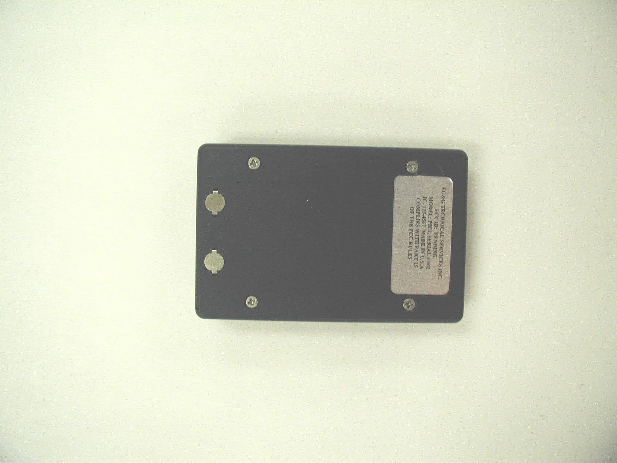
QUZ126988A
Sep 23, 2004PERSONAL ID CREDENTIAL FIELD DISTURBANCE SENSOR
Equipment Class
FDS - Part 15 Field Disturbance Sensor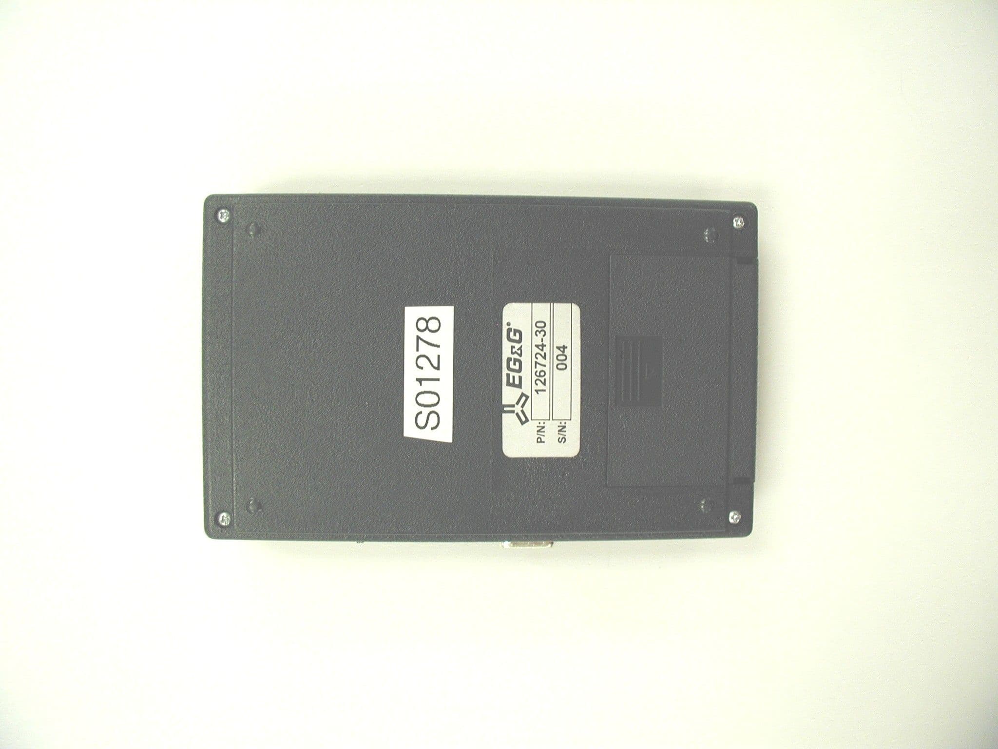
QUZ126724A
Sep 23, 2004PERSONAL ID CREDENTIAL ENROLLMENT STATION
Equipment Class
FDS - Part 15 Field Disturbance Sensor
QUZ126742A
Sep 23, 2004PERSONAL ID CREDENTIAL SYSTEM READER
Equipment Class
FDS - Part 15 Field Disturbance Sensor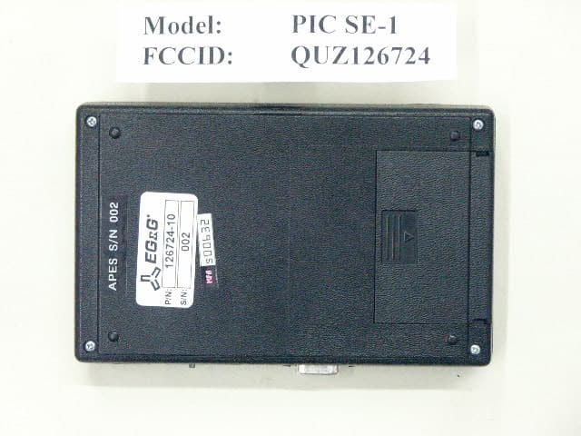
QUZ126724
Jun 22, 2003Personal ID Credential Enrollment Station
Equipment Class
FDS - Part 15 Field Disturbance Sensor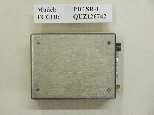
QUZ126742
Jun 22, 2003Personal ID Credential System Reader
Equipment Class
FDS - Part 15 Field Disturbance Sensor