QVBLS020Wind Speed Indicator
Load Systems International, Inc.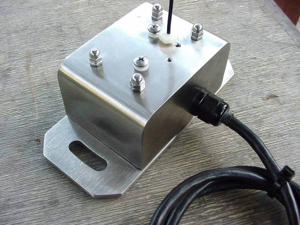
Click to zoom
Application Details
- Equipment Class
- DXX - Part 15 Low Power Communication Device Transmitter
- Date of Grant
- Mar 17, 2003
- Application Purpose
- Original Equipment
- Date of Application
- Mar 17, 2003
- Equipment Note
- Wind Speed Indicator
- Frequency Range
- 903.30000000 - 921.30000000
- Country
- Canada
Documents & Files
Document Text
Text extracted from the exhibit documents filed with the FCC. Open a document above to read the original.
Users Manual
1 LS420 Universal User Manual V2.91 2003-01-21.doc LSI Load Systems International LS 420 – Two lines display – Universal User Manual GENERAL: The LS420 is a wireless capable display which shows the measurements taken by up to nine sensors linked in a local radio frequency network that can include any combination of load cells, angle sensors, anti-two-block switches and a wind sensor. This unit is compatible with the LSI network allowing full expansion. New LSI sensors may be added and existing LSI sensors may remain in use when upgrading to a future display generation. 2 LS420 Universal User Manual V2.91 2003-01-21.doc Table of Contents System Description and Features.........................................................................................3 Important Note on System Operation and Start-up:........................................................4 Contact Information:..................................................................................................................4 1.1 LS420 Indicator Lights...........................................................................................................5 1.2 LS420 Display Screen Abbreviations....................................................................................5 1.3 LS420 Buttons.......................................................................................................................6 1.4 LS420 Display Options..........................................................................................................8 Chapter 2: Installation..............................................................................................................9 2.1 Display Unit Installation.........................................................................................................9 2.2 Load Cell Installation V1.2...................................................................................................13 2.3 Angle Sensor Installation.....................................................................................................14 2.4 Anti-two-block switch installation V2.0................................................................................16 2.5 Installation of a length sensor cable reel.............................................................................19 2.6 Installation of radius calculation V1.0..................................................................................20 Chapter 3: Changing Batteries............................................................................................24 3.1 Changing Load Sensor Batteries V1.4................................................................................24 3.2 Changing Angle Sensor Batteries V1.4..............................................................................27 3.3 Changing Anti-two-block Batteries V1.5.............................................................................30 Chapter 4: Replacing Antennae..........................................................................................31 4.1 Replacing Load, Angle and Two-block Sensor Antennae V2.1..........................................31 Chapter 5: Adding and Removing Sensors.....................................................................33 5.1 How To Add A Sensor to the LS420...................................................................................33 5.2 How to Remove A Sensor from the LS420.........................................................................34 5.3 Changing Sensor Configuration of the LS420....................................................................34 Chapter 6: Troubleshooting 1.0...........................................................................................36 6.1 The Display Unit Does Not Light Up...................................................................................37 6.2 The Lock-out Doesn't Engage.............................................................................................38 6.3 The Display Unit Is Always In Alarm Mode, The "2 Block" warning light is on...................39 6.4 The Display Unit Is Always In Alarm Mode, the main hoist green light is flashing.............39 6.5 The Display Unit Is Always In Alarm Mode, the Load warning light is on..........................40 6.6 The Display Unit Is Always In Alarm Mode, the Limit+ or Limit- warning light is flashing..41 6.7 The Display Unit Is Always In Alarm Mode, the wind speed alarm message is flashing...42 6.8 Radio Communication Problem..........................................................................................43 Chapter 7: Purchasing and Customer Service...............................................................44 3 LS420 Universal User Manual V2.91 2003-01-21.doc System Description and Features The LS420 system detects and displays load and capacity related information and can warn the operator when a limit is exceeded or a two-block event is pending. This system is an operator aid and should not be solely relied upon for safe hoist operation. The op- erator must at all times be fully aware of the approach of the hook block to the head sheave, the length and angle of the boom and jib, the hoist and crane configuration and rigging (including parts of lines, counter-weights, outriggers, rotation etc.) and the ap- propriate capacity charts. This system is designed as a backup to the operator in the event that he has exceeded the safe limits of the crane. - Displays information from up to nine wireless sensors including load cells, angle sen- sors, wind speed sensors and anti-two-block switches. - Adjustable load limits and overload warning for hoists. - Adjustable maximum and minimum angle limits with warning for booms and luffing jibs. - Anti-two-block alarm and bypass. - Waterproof. - Multi-position mounting bracket. - All sensors pre-calibrated. - Parts of lines setting. - Tare function. - Bar graph display of percentage of load limit on load cells. -…
Text truncated - open the document above for the full version.
Attestation Statements
Page 1 of 4 http://www.celectronics.../WorldClient.dll?Session=BSUALLB&View=Message&Number=562/24/03 Hi Kyle. The antenna is made of steel wire with a strong plastic sheath. A male AMP style connector is crimped to one end and the other end is capped with a heat-shrinkable cap. The antenna wire is placed inside a customized nylon nut with a hole in its center and that nut screwed onto the sensor enclosure where the antenna connector mates with a female connector soldered onto the PC board. Once tightened, the male connector on the antenna wire is securely connected to the female PCB connector and the nylon nut can only be removed with tools, it cannot be removed by hand. The reason for using this type of connection is to facilitate production assembly of the devices. If an antenna is damaged, it can be replaced at the factory. Hope this helps. Thanks, Marc Boivin LSI Inc. -----Original Message----- From: Kyle Fujimoto [mailto:[email protected] ] Sent: 21 février, 2003 20:02 To: Marc Boivin Subject: Please explain how the antenna is attached Marc, Please explain how the antenna is connected to the units. The TCB wanted a more complete description of how it is connected (they did not like my description of hard wired to the unit). That is they would like to know how the conductor for the antenna is connected to the PCB (more specific than just 'hard wired'). We have received another unit for testing next week. Thank you, Kyle Fujimoto Test Engineer -- Compatible Electronics, Inc. -- Brea Division Phone:(714) 579-0500 Fax: (714) 579-1850 [email protected] http://www.celectronics.com From: "Marc Boivin" <[email protected]> To: "Kyle Fujimoto" <[email protected]> Date: 02/24/2003 10:15 AM Subject: RE: Please explain how the antenna is attached
Block Diagram
text CPU 68HC08 Family Flash uProcessor Linear Power Regulator (3.3V LDO) RF Module (900MHz) 32 kHz Crystal + Filter Batteries 3 "C" Cells (4.5VDC Total) Sensors - Load - Angle - 2xADC - Wind speed - A2B (Switch) - Temperature Sensor Block Diagram
Operational Description
EXPOSITORY STATEMENT The EUT is a wind speed indicator that transmits signals from its attached anemometer to a receiver to monitor the instantaneous wind speed. The EUT is part of a system that is used to monitor various parameters when operating a crane.
Schematics
1234 A B C D 4 321 D C B A Title NumberRevisionSize B Date:9-Dec-2002 Sheet of File:S:\Projects\..\LoadSensor V3.1 2002-12-04.schDrawn By: R1 10M C1 0.1uF/50V + C5 10uF/16V/Tan X1 32768Hz FSR327 GND 1 ANT 2 CSO 3 CS1 4 CS2 5 CTS 6 PDN 7 VCC 8 GND 9 AIN 10 U2 Linx TXM-900-HP-II VCC + C6 10uF/16V/Tan C8 22pF/50V C9 22pF/50V VCC R3 200 PB0 PB1 PB2 PB3 PB4 R4 332K R5 332K +4.5V PB7 R7 10K 2 3 1 Q1 MMBT3906 *IRQ Rx Tx *RESET 1 2 3 4 JP2 HEADER 4 R10 1K PA1 PA2 PA3 PA4 PA5 PA6 Si/o 1 SC 2 NC 3 Gnd 4 NC 5 NC 6 CS 7 V+ 8 U4 LM74CIM3 R9 10K 2 3 1 Q2 MMBT3906 Rg1 1 Vin- 2 Vin+ 3 V- 4 Vref 5 Vout 6 V+ 7 Rg2 8 U5 INA122U C11 0.1uF/50V +3V RF +3V Analog and Acc. 900 MHz transmitter radio module. R17 10K C12 0.1uF/50V C13 0.1uF/50V 2002-12-04 R11 1.21K +4.5V PTC3 5 PTC4 6 PTC2 4 PTC5 7 PTC1 3 PTC6 8 PTC0 2 PTB0/AD0 22 PTB1/AD1 23 PTB2/AD2 24 PTB3/AD3 25 PTB4/AD4 26 PTB5/AD5 27 PTB6/AD6 28 PTB7/AD7 29 PTA0/KBD0 32 PTA1/KBD1 33 PTA2/KBD2 34 PTA3/KBD3 35 RESET 1 PTA4/KBD4 36 PTA5/KBD5 37 OSC1 44 PTA6/KBD6 38 OSC2 43 PTA7/KBD7 39 IRQ 11 PTE0/TxD 9 PTE1/RxD 10 PTD0/SS 12 PTD1/MISO 13 PTD2/MOSI 14 PTD3/SPSCK 15 VSS 16 VDD 17 PTD4/T1CH0 18 PTD5/T1CH1 19 PTD6/T2CH0 20 PTD7/T2CH1 21 VSSAD/VREFL 31 VDDAD/VREFH 30 CGMXFC 42 VSSA 41 VDDA 40 U7 68HC908GP32ACFB R21 332K R18 10K C16 .033uF C17 .01uF VCC C18 .01uF GND 4 DOUT 6 CS/SD 5 DCLK 7 IN- 3 IN+ 2 VREF 1 VCC 8 U8 ads7822uc 1 2 3 4 JP1 HEADER 4 R12 1K Rg1 1 Vin- 2 Vin+ 3 V- 4 Vref 5 Vout 6 V+ 7 Rg2 8 U6 INA122U R19 10K C14 0.1uF/50V C15 0.1uF/50V R13 1.21K GND 4 DOUT 6 CS/SD 5 DCLK 7 IN- 3 IN+ 2 VREF 1 VCC 8 U9 ads7822uc Battery1 Battery2 Battery3 'C' Holder Keystone 2230 C3 0.1uF/50V + C19 470uF/10V/Al C4 0.1uF/50V D1 1N4148 *IRQ VCC VCC R22 10K VCC PA0 PTD2 PTD3 PTD4 PTD5 PTD2 PTD3 PTD4 PTD5 R25 1M R26 1M R27 1M R28 1M VCC *RESET PA0 1 2 3 4 5 6 7 8 JP3 Programming VCC VCC Rx Tx 1 Ant2 AntennaGnd 1 Ant1 Antenna Ant Rg1bRg1a Rg2aRg2b Vout2 Vout1Vout1f Vout2f +1.5V Batt +3.0V Batt C20 0.1uF/50V +3V RF +3V Analog and Acc. 1 2 3 45 6 7 8 DS1DIP SWITCH 4 VIN 8 FDBK 7 SHTDN 3 TAP 6 SENS 2 VOUT 1 ERR 5 U1 LP2951ACM-3.3 PC4 PC4 R23 10K Osc1 Osc2 CGMXFC LED1 MV5774C(LS)/SSL-LX3059IGW(Angle) C23 0.1uF/50V Load Angle Wind Length A2B Communication & Programmation Circuit V3.1 C2 1uF C10 0.1uF/50V C21 Do not solder (0.1uF) D2 1n4148 D3 1n4148 R8 1M To ADC ADS7816 Part attributes A: Angle sensor B: A2B C: Communication L: Load Sensor P: Programming board R: Reel Length sensor T: Ultrasound Boom Tip Module U: Ultrasound Echo Transmitter X: eXperimentation W: Wind sensor 2: 2XAdc SW1 ReedSw Alarm R14 1M SW2 ReedSw Safe R15 100K RCAL1 1K R16 1M R20 1M R24 1M 3 2 1 8 4 U3A LMC6442AIM VCC C1+ 1 C1- 3 C2+ 4 C2- 5 Vs+ 2 Vs- 6 VCC 16 GND 15 T1IN 11 T1OUT 14 T2IN 10 T2OUT 7 R1OUT 12 R1IN 13 R2OUT 9 R2IN 8 U10 max232 C25 0.1uF/50V C26 0.1uF/50V C27 0.1uF/50V C28 0.1uF/50V 1 23 U11A 74HC125D 4 56 U11B 74HC125D PA0 VCC C29 0.1uF/50V DB9-Pin3-Tx DB9-Pin2-Rx 1 6 2 7 3 8 4 9 5 J1 DB9 GND 7 89 10 VCC 14 U11C 74HC125D 1112 13 U11D 74HC125D VCC Mx+10V Mx-10V MxC1+ MxC1- MxC2+ MxC2- DB9-4_DTR 5 6 7 U3B LMC6442AIM D4 1n4148 C24 0.1uF/50V F1 500mA R45 0 R46 0 R47 1.2M opt R48 1.6M opt Tx Rx Vout2f Conn2-2 Conn2-3 Conn2-2 Conn2-3 AOSI Angle Sensor Wind Sensor Section Programming & Communication section Conn1-2 Conn1-2 Conn1-3 Conn1-3 +cap0.1uF +cap0.1uF Vout1f VCC R29 13 R30 13 R49 82 T2CH0 T2CH1 Solder R14 (1K) Angle Sensor A2B To erase, connect PC4 to Vcc PA0 to Gnd RealAnt R31 0ohm opt Conn1-2Vout1 LED2 MV5774C R54 200 VCC PTC2 PTC2 Rx Tx PA0 1 2 3 4 5 6 7 8 JP4 A2B Programming VCC LX 7 *SHDN 5 LBI 2 REF 4 Out 8 FB 1 *Lbo 3 Gnd 6 U101 L6920 C102 47uF EEFCDJ470R L1 ELL6RH100M C103 C104 0.1uF/50V VCC C101 47uF EEFCDJ470R R101 1M R102 1M 1 2 3 J2 CON3 SW3 ReedSw Safe R55 0 VCC C42 0.01uF R57 0 * R65 332K VCC R59 332K R60 332K R61 332K R62 332K R63 332K R64 332K R6 0 +3.0V Batt C7 100uF/6.3V *LBO *LBO VCC +4.5V D5 0 D6 1N4148 D7 1N4148 R2 0 +4.5V R32 0 R33 10K 2 3 1 Q3 MMBT3906 VCC D8 1n4148 Do not solder C21 if C12 is soldered EB 2002-09-11 update on part field for assembly recipies + 100uF sur C14 EB 2002-10-25 update to antenna resistors VCC 1 GND 2 OUTPUT 3 U12 A3212_HALL_EFFECT VCC C22 0.1uF C30 10pF R34 50K VCC *IRQ C31 CAPACITOR R350 Conn1-3Vout2f R36 0 Conn1-2Vout1f R37 0 Conn2-3Vout2f R38 0 Conn2-2Vout1f MB 2002-12-04 ask to the head -:)))))
Test Report
Report Number: B21213D1 FCC Part 15 Subpart B and FCC Section 15.249 Test Report Wind Speed Indicator Model: LS020 114 OLINDA DRIVE, BREA, CALIFORNIA 92823 PHONE: (714) 579-0500 FAX: (714) 579-1850 Page 1 of 15 FCC PART 15, SUBPART B and C TEST REPORT for WIND SPEED INDICATOR MODEL: LS020 Prepared for LOAD SYSTEMS INTERNATIONAL, INC. 4495 BOUL. WILFRID-HAMEL, BUREAU 110 QUEBEC, QUEBEC G1P 2J7 Prepared by:_____________________ KYLE FUJIMOTO Approved by:____________________ MICHAEL CHRISTENSEN COMPATIBLE ELECTRONICS INC. 114 OLINDA DRIVE BREA, CALIFORNIA 92823 (714) 579-0500 DATE: FEBRUARY 19, 2003 REPORT APPENDICES TOTAL BODY A B C D E PAGES 15 2 2 2 10 8 39 This report shall not be reproduced except in full, without the written approval of Compatible Electronics. Report Number: B21213D1 FCC Part 15 Subpart B and FCC Section 15.249 Test Report Wind Speed Indicator Model: LS020 114 OLINDA DRIVE, BREA, CALIFORNIA 92823 PHONE: (714) 579-0500 FAX: (714) 579-1850 Page 2 of 15 TABLE OF CONTENTS Section / Title PAGE GENERAL REPORT SUMMARY 4 SUMMARY OF TEST RESULTS 4 1. PURPOSE 5 2. ADMINISTRATIVE DATA 6 2.1 Location of Testing 6 2.2 Traceability Statement 6 2.3 Cognizant Personnel 6 2.4 Date Test Sample was Received 6 2.5 Disposition of the Test Sample 6 2.6 Abbreviations and Acronyms 6 3. APPLICABLE DOCUMENTS 7 4. Description of Test Configuration 8 4.1 Description of Test Configuration - EMI 8 4.1.1 Cable Construction and Termination 9 5. LISTS OF EUT, ACCESSORIES AND TEST EQUIPMENT 10 5.1 EUT and Accessory List 10 5.2 EMI Test Equipment 11 6. TEST SITE DESCRIPTION 12 6.1 Test Facility Description 12 6.2 EUT Mounting, Bonding and Grounding 12 7. Test Procedures 13 7.1 Radiated Emissions (Spurious and Harmonics) Test 13 8. CONCLUSIONS 15 Report Number: B21213D1 FCC Part 15 Subpart B and FCC Section 15.249 Test Report Wind Speed Indicator Model: LS020 114 OLINDA DRIVE, BREA, CALIFORNIA 92823 PHONE: (714) 579-0500 FAX: (714) 579-1850 Page 3 of 15 LIST OF APPENDICES APPENDIX TITLE A Laboratory Recognitions B Modifications to the EUT C Additional Models Covered Under This Report D Diagrams, Charts, and Photos • Test Setup Diagrams • Radiated Emissions Photos • Antenna and Effective Gain Factors E Data Sheets LIST OF FIGURES FIGURE TITLE 1 Plot Map And Layout of Test Site Report Number: B21213D1 FCC Part 15 Subpart B and FCC Section 15.249 Test Report Wind Speed Indicator Model: LS020 114 OLINDA DRIVE, BREA, CALIFORNIA 92823 PHONE: (714) 579-0500 FAX: (714) 579-1850 Page 4 of 15 GENERAL REPORT SUMMARY This electromagnetic emission test report is generated by Compatible Electronics Inc., which is an independent testing and consulting firm. The test report is based on testing performed by Compatible Electronics personnel according to the measurement procedures described in the test specifications given below and in the "Test Procedures" section of this report. The measurement data and conclusions appearing herein relate only to the sample tested and this report may not be reproduced without the written permission of Compatible Electronics, unless done so in full. This report must not be used to claim product endorsement by NVLAP or any other agency of the U.S. Government. Device Tested: Wind Speed Indicator Model: LS020 S/N: N/A Product Description: See Expository Statement. Modifications: The EUT was not modified during the testing. Manufacturer: Load Systems International, Inc. 4495 Boul. Wilfrid-Hamel, Bureau 110 Quebec, Quebec G1P 2J7 Test Date: December 13, 2002 Test Specifications : EMI requirements CFR Title 47, Part 15 Subpart B; and Subpart C, Sections 15.205, 15.209, and 15.249 Test Procedure: ANSI C63.4: 1992 Test Deviations: The test procedure was not deviated from during the testing. SUMMARY OF TEST RESULTS TEST DESCRIPTION RESULTS 1 Conducted RF Emissions, 450 kHz - 30 MHz This test was not performed because the EUT operates on DC power only and cannot be plugged into the AC public mains. 2 Radiated RF Emissions, 10 kHz - 9300 MHz Complies with the Class B limits of CFR Title 47, Part 15, Subpart B; and Subpart C, sections 15.205, 15.209, and 15.249. Highest Reading in Relation to Spec Limit: 93.90 dB μ V @ 903.30 MHz (*U c = 2.05 dB) *U c = Combined Standard Uncertainty Report Number: B21213D1 FCC Part 15 Subpart B and FCC Section 15.249 Test Report Wind Speed Indicator Model: LS020 114 OLINDA DRIVE, BREA, CALIFORNIA 92823 PHONE: (714) 579-0500 FAX: (714) 579-1850 Page 5 of 15 1. PURPOSE This document is a qualification test report based on the Electromagnetic Interference (EMI) tests performed on the Wind Speed Indicator Model: LS020. The EMI measurements were performed according to the measurement procedure described in ANSI C63.4: 1992. The tests were performed in order to determine whether the electromagnetic emissions from the equipment under test, referred to as EUT hereafter, are within the Class B specification limits defined by CFR Title 47, Part 15, Subpart B; and Subpart C, sections 15.205, 15.209, and 15.249. Report Number: B21213D1 FCC Part 15 Subpart B and FCC Section 15.249 Test Report Wind Speed Indicator Model: LS020 114 OLINDA DRIVE, BREA, CALIFORNIA 92823 PHONE: (714) 579-0500 FAX: (714) 579-1850 Page 6 of 15 2. ADMINISTRATIVE DATA 2.1 Location of Testing The EMI tests described herein were performed at the test facility of Compatible Electronics, 114 Olinda Drive, Brea, California 92823. 2.2 Traceability Statement The calibration certificates of all test equipment used during the test are on file at the location of the test. The calibration is traceable to the National Institute of Standards and Technology (NIST) . 2.3 Cognizant Personnel Load Systems International, Inc. Marc Boivin Head Of Electrical Engineering Compatible Electronics, Inc. Kyle Fujimoto Test Engineer Kirit Ramani Test Engineer Michael Christensen Test Engineer 2.4 Date Test Sample was Received The test sample was received on December 13, 2002. 2.5 Disposition of the Test Sample The sample has not b…
Text truncated - open the document above for the full version.
Contact Information
Applicant
Eric Beaulieu(Engineer)
Technical Contact
Compatible ElectronicsKyle Fujimoto
[email protected]714-579-0500
114 Olinda Drive · Brea, California · United States
Test Firm
Compatible ElectronicsScott McCutchan
714-579-0500Fax: 714-579-1850
Technical Specifications
| # | Rule Parts | Frequency Range | Power Output |
|---|---|---|---|
| 1 | 15C | 903.3 MHz - 921.3 MHz | - |
Other Applications from Load Systems International, Inc.
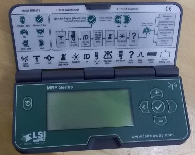
QVBMBR001
Jan 24, 2016Multi Sensor Display
Equipment Class
DTS - Digital Transmission System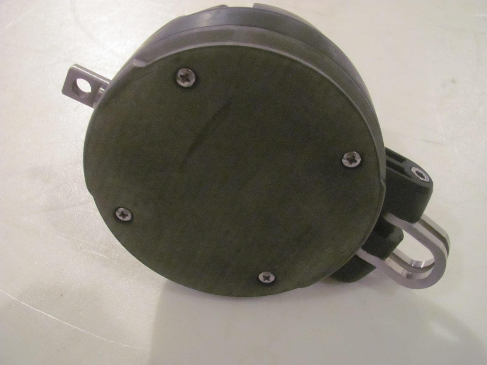
QVBGS002
Jan 22, 2013GS025: Radio Anemometer, GS085: Radio Ant-Two-Block
Equipment Class
DTS - Digital Transmission System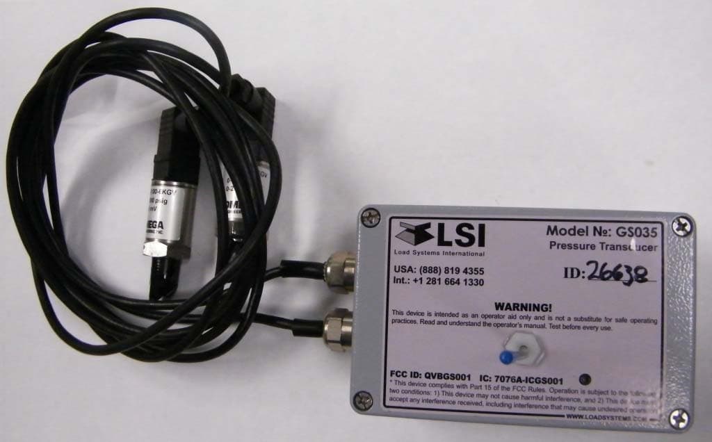
QVBGS001
May 11, 2010GS012: Angle Length Sensor; GS035: Pressure Transducer
Equipment Class
DTS - Digital Transmission System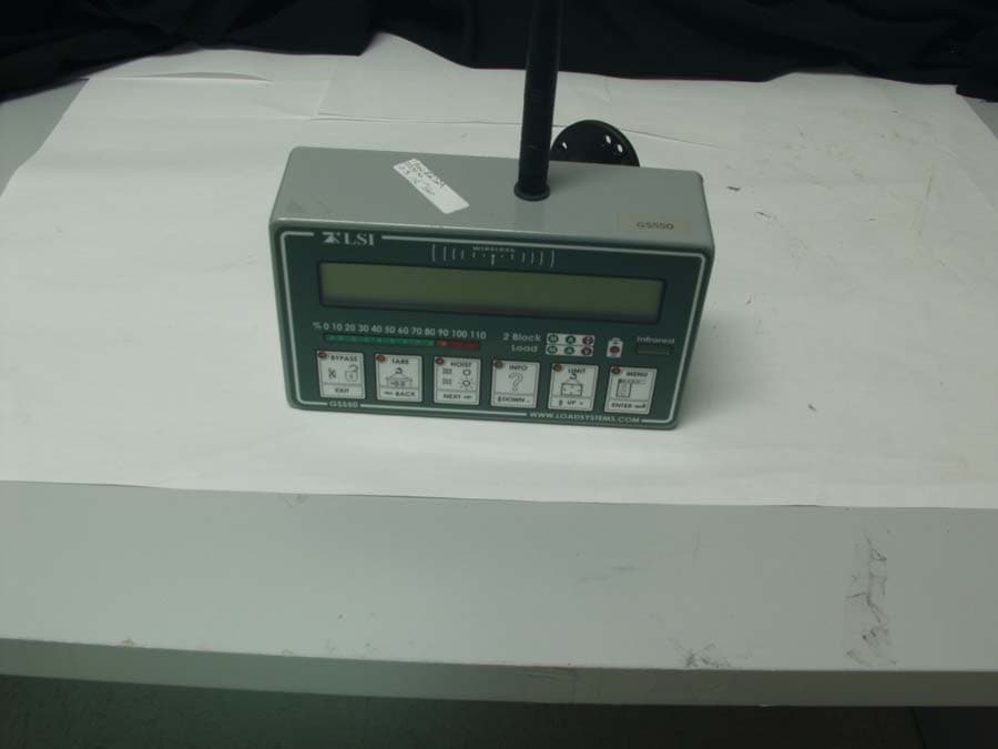
QVBGS550
May 30, 2007Spread Spectrum Transmitter
Equipment Class
DTS - Digital Transmission System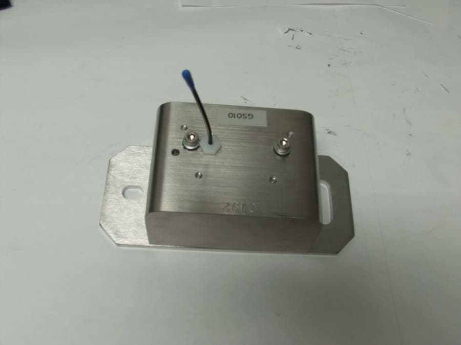
QVBGS000
May 30, 2007Spread Spectrum Transmitter
Equipment Class
DTS - Digital Transmission System