QVN-HFK2MI4Wireless Microphone
Euro Communication Equipement SAS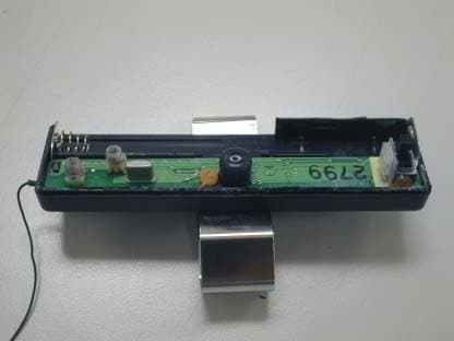
Click to zoom
Application Details
- Equipment Class
- DXX - Part 15 Low Power Communication Device Transmitter
- Date of Grant
- Mar 31, 2003
- Application Purpose
- Original Equipment
- Date of Application
- Mar 31, 2003
- Equipment Note
- Wireless Microphone
- Frequency Range
- 40.67500000 - 40.67500000
- Country
- France
Documents & Files
Document Text
Text extracted from the exhibit documents filed with the FCC. Open a document above to read the original.
Users Manual
Remark: - In standby mode, the microphone will still have a small consumption (less the 1.8 microwatts). - In order to extend your battery life, it is highly recommended to switch “OFF” your microphone when not using for a long time. FUNCTION CONTROLS Adjust the Function Controls as recommended: A. Tone Control “H“ for High Tone. “L” for Low Tone. B. ASP Control ON = Echo and Feedback Canceller. OFF = Echo Reducer only. C. Adjustable Mike Gain(MIC) Control “H” for high gain ; “L” for low gain. Microphone gain "L" is necessary in noisy background. The Mike gain must be adjusted to match with your cell phone model. If the gain is too high, it can cause feedback (whistling sound), echo or background noise during calls on some cell phones. SETTING THE VOLUME There are two volume controls on the unit. One is on the main unit (10) and controls only the main speaker (6). The other is on the headset (8) and sets both the earphone (11) and the main speaker (6). The headset volume control (8) is digital and is combined with the multi-function button. Pressing it clockwise increases the volume. Counter-clockwise decreases it. Continuous pressing of the digital volume control can also rapidly set the volume. During a communication, pick-up the earphone and adjust it’s volume (8). Replace the earphone on the base and adjust the speaker volume (10). If the volume is too high, it can cause feedback (whistling sound), echo or background noise during calls on some cell phones. ANSWERING / RECEIVING A CALL When phone is receiving a call, the phone ring tone will be heard on the hands-free kit or on the headset. Just press the button (4 on the main unit, 8 on the headset) once to answer the call. Pressing the button again will hang-up and terminates the call. MAKING A CALL Calling through the hands-free kit can be done using voice tags (refer to the phone user manual on saving and activating voice tags). The steps are: 1. Press the button (4) once on the main unit or the headset button (8) to activate the voice dialing. 2. A beep will then be heard prompting the user to say the name of the person to call. 3. Say the name. 4. The phone will then place the call automatically. In case the phone does not recognize the name spoken, the steps above may be repeated. 5. Press the button again to terminate the call. If the desired number to be dialed has no voice tag, normal dialing can also be done using the keypad on the phone. After dialing, audio is transferred automatically to the unit. When connected, pressing the button (4 or 8) will hang-up and terminates the call. OPERATING MANUAL MULTI-TOOTH Bluetooth Enabled Hands-Free Kit / Headset Recommended Function Controls Setting (Working on all models): MIC = L ASP = ON TONE = H Note : On high background environment, If you experience audio level fluctuation, turn ASP ‘’ OFF ’’ . USER’S MANUAL This unit uses Bluetooth technology that allows wireless communications on devices such as cellular phones. This is designed to be a totally wireless hands-free car kit or a stand- alone wireless headset. This provides the user to operate a cellular phone inside the car while driving and can also be used anywhere by detaching the headset and becomes a stand-alone Bluetooth headset. The unit may possibly work on all Bluetooth cellular phones provided that they respect the Bluetooth protocol. ILLUSTRATIONS: 1 – Magnet 2 – Charging Pins 3 – Charge/Power Indicator 4 – Line Pick-up Button 5 – Cigarette Lighter Plug 6 – Main Speaker 8 – Multi-function Button (Talk/Power/Volume) 9 – Microphone / Indicator lights 10 – Speaker Volume 11 – Earphone OPERATIONS TURNING ON/OFF THE UNIT When using as a hands-free car kit, plugging it in the cigarette lighter jack activates the unit. When using as a headset, pressing down the button (8) for 2 seconds turns it ON. When ON, a low-high tone is heard and a continuous blue light will show (red indicates low- battery). After releasing the button the unit is now ready and is waiting for a call (standby mode). If the indicator becomes red, it means that the battery on the headset is low. Re-charge it immediately by putting it back to the main unit. As a headset, pressing the button (8) for 4 to 10 seconds will turn it OFF depending on the phone. A high-low tone will then be heard and the indicator lights becomes red then turns off after a few seconds. Wait at least for 4 seconds before to turn the headset on again. Turning off of the headset is necessary to conserve battery life, in the case the headset will not be used for a long time. PAIRING TO THE PHONE Before use, the hands-free kit must be paired with the phone. Pairing is done only once. When the phone and the unit is already paired, connection to the phone will be automatic anytime when the phone is used. Pairing steps: 1. Bring the cellular phone in close proximity with the unit. 2. Detach the headset from the main unit. 3. Turn off the headset. This is done by pressing down the headset button (8) for 4 seconds. A high-low tone will be heard. Release the button. The light will become red and turns off after a few seconds. 4. From OFF state, press the button again for 10 seconds. Then a low-high tone is heard and the blue indicator will light indicating the unit is now ON. 5. Continue pressing down the button (8) until a distinctive three-tone sound will be heard and a red and blue light will alternately blink. This indicates that the unit is ready for pairing. 6. Perform a device scan or discovery on the cellular phone. Refer the phone users manual for this procedure. 7. Enter “0000” as the passkey or passcode. If the pairing is successful, the alternating red/blue lights will stop. 8. If the pairing is unsuccessful, the steps above may be repeated. The unit is now ready to link calls from the phone directly to the headset. INSTALLING THE MICROPHONE 1. Put two (2) "AAA" Alkaline batteries in the wireless microphone. Note: Microphone battery life is more than 500 calls (if 3 calls/day, ba…
Text truncated - open the document above for the full version.
Block Diagram
Block Diagram of HFK2MI4 m i crophone Q1 AMP Ant Q5 AMP Crystal Oscillator p owe r -of f Ti m e r Mic
Cover Letter(s)
Federal Communication Commission Equipment Authorization Division, Application Process Branch 7435 Oakland Mills Road Columbia, MD 21048 U.S.A February 6, 2003 TO WHOM IT MAY CONCERN Pursuant to Paragraphs §0.457 and 0.459 of the Commission Rules (47 C.F.R.) and the Section § 552(b)(4) of the Freedom of Information Act, Euro Communication Equipements SAS. requests confidentiality for the following products: FCCID QVN-HFK2MI4 FCCID QVN-BTEAR For the product stated above, we request that the following information be held confidential: 1) Electrical Schematics of the Circuitry No other items submitted as part of the equipment authorization filing process are deemed confidential. The above exhibits contain Euro Communication Equipements SAS trade secrets and proprietary information that could be of benefit to our competitors regarding the design of our Wireless microphone and wireless headset. This material is not customarily available to the general public and we request that it be withheld from public inspection. If you have any questions, please feel free to contact me. Sincerely, Jason Lin Assistant Manager E&E department , SGS Taiwan
External Photos
External Photos
Internal Photos
Internal Photos
Operational Description
Technical description of the HFK2MIC: The HFK2MIC unit is an FM wireless microphone and transmits at the frequency of 40.675MHz for Handsfree car kit application. The audio signal will be received into the omni directional electret microphone, the incoming signal will be amplified by Q1 and Q5 - BC847. The audio signal is feed-thru the Varicap diode D3 -1SV214 of the crystal controlled Colpitts Oscillator, consisting of Q6-BF93 and X1-crystal with tuning inductors / capacitors. The antenna is a flexible wire extended outside the plastic box. The unit is also equipped with a power-off delay of 3minutes by the ICs U1 and U2, for powersaving. 2.3V Low battery detection is sensed by U3 with Led indicators. The power source is 3V given by two (2) AAA alkaline batteries.
Test Report
Report No. : ER/2003/10007 Page : 1 of 16 FCC TEST REPORT Equipment Under Test : Wireless Microphone Model No. : HFK2MI4 Applicant : Euro Communication Equipments SAS Route de Foix 11500 NEBIAS Quillan, France Address of Applicant : Standards: FCC Part 15 subpart C In the configuration tested, the EUT complied with the standards specified above. Remarks: This report details the results of the testing carried out on one sample, the results contained in this test report do not relate to other samples of the same product. The manufacturer should ensure that all products in series production are in conformity with the product sample detailed in this report. This report may only be reproduced and distributed in full. If the product in this report is used in any configuration other than that detailed in the report, the manufacturer must ensure the new system complies with all relevant standards. Any mention of SGS Taiwan EMC Services or testing done by SGS Taiwan EMC Services in connection with distribution or use of the product described in this report must be approved by SGS Taiwan EMC Services in writing. Tested by : Robert Chang Date : Mar. 17, 2003 Approved by : Jason Lin Date : Mar. 17, 2003 Report No. : ER/2003/10007 Page : 2 of 16 Contents 1. General Information 1.1 Testing Laboratory 3 1.2 Details of Applicant 3 1.3 Description of EUT(s) 3 1.4 Operation Procedure 3 2. Summary of Results 4 3. Instruments List 5 4. Measurements 6 4.1 Radiated emission Limits, general requirement 6 4.2 Field Strength Limit 9 4.3 Frequency Stability on Extreme condition 10 APPENDIX Photographs of Test Setup 14 Photographs of EUT 15-16 Report No. : ER/2003/10007 Page : 3 of 16 1. General Information 1.1 Testing Laboratory SGS Taiwan Ltd. ( FCC Registration number: 573967 ) 1F, No. 134, Wukung Road, Wuku industrial zone Taipei county , Taiwan , R.O.C. Telephone : +886-2-2299-3279 Fax : +886-2-2298-2698 Internet : http://www.sgs.com.tw 1.2 Details of Applicant Name : Euro Communication Equipments SAS Address : Route de Foix 11500 NEBIAS Quillan, France Contact : Mr. Michel Marchant Telephone : +33-4-68208730 1.3 Description of EUT(s) 1 Product name Wireless Microphone 2 Product ID HFK2MI4 3 Supply Voltage Power by 2 AAA battery , 3V 4 Carrier Frequency 40.675Mhz 1.4 Operation Procedure Turn on EUT and put it in the center of Turn-table, measuring distance is 3 meter. When performing extreme condition test, put the EUT in the climatic chamber, adjust the temperature and measured by near-field probe. Testing requirement follows CFR47, Part 15.229 , testing site comply with the requirement of ANSI C63.4 standard. Report No. : ER/2003/10007 Page : 4 of 16 2.Summary of Results subclause Parameter to be measures Verdict Page 15.209 Radiated emission Limits, general requirement PASS 6 15.229(a) Field Strength Limit PASS 9 15.229(d) Frequency Stability on Extreme condition PASS 10 Report No. : ER/2003/10007 Page : 5 of 16 3. Instruments List Instrument Model Serial number Calibration date Spectrum Analyzer Agilent 7405A US40240202 May 22, 2002 Antenna Schwarzbeck VULB9163 159 July 1, 2002 Climatic chamber Terchy MHG 120LN/A N/A EMC Analyzer HP 8594EM 3624A00203 Dec. 13, 2002 Report No. : ER/2003/10007 Page : 6 of 16 4. Measurements 4.1 Radiated emission Limits, general requirement SUBCLAUSE 15.209 30Mhz-1000Mhz Horizontal Report No. : ER/2003/10007 Page : 7 of 16 30Mhz-1000Mhz Vertical Report No. : ER/2003/10007 Page : 8 of 16 4.2.1 Limits Report No. : ER/2003/10007 Page : 9 of 16 4.2 Field Strength Limit SUBCLAUSE 15.229(a) (a) Unless operating pursuant to the provisions in Section 15.231, the field strength of any emissions within this band shall not exceed 1000 microvolts/meter at 3 meters. Center Freq: f=40.675 Mhz Real Value = 38.24 (read value) + 12.33 (Ant factor) + 0.47 (cable loss) = 51.04 db V Report No. : ER/2003/10007 Page : 10 of 16 4.3 Frequency Stability on Extreme condition SUBCLAUSE 15.229(d) (d) The frequency tolerance of the carrier signal shall be maintained within +/- 0.01% of the operating frequency over a temperature variation of -20 degrees to + 50 degrees C at normal supply voltage, and for a variation in the primary supply voltage from 85% to 115% of the rated supply voltage at a temperature of 20 degrees C. For battery operated equipment, the equipment tests shall be performed using a new battery. conditions Nominal-20 C 50 C 3.45V 2.55V Center freq.(Mhz) 40.675 40.678 40.67340.675 40.675 Deviation (%) N/A 0.0073 -0.00490 0 Nominal voltage = 3V 0.85 * 3V = 2.55V 1.15 * 3V = 3.45V Report No. : ER/2003/10007 Page : 11 of 16 Nominal condition( voltage = 3V, Temperature = 20 C, measured by near-field probe Report No. : ER/2003/10007 Page : 12 of 16 Measured at –20 C Measured at 50 C Report No. : ER/2003/10007 Page : 13 of 16 Measured at 3.45 Voltage supply Measured at 2.55 voltage supply Report No. : ER/2003/10007 Page : 14 of 16 Appendix : Test setup Photos <The photos are saved separately> Report No. : ER/2003/10007 Page : 15 of 16 External Photos <The photos are saved separately> Report No. : ER/2003/10007 Page : 16 of 16 Internal Photos <The photos are saved separately>
Test Setup Photos
APPENDIX: Photographs of Test Setup
Contact Information
Applicant
Michel E Marchant(President)
Test Firm
SGS Taiwan Ltd.Wyse Chiu
Technical Specifications
| # | Rule Parts | Frequency Range | Power Output |
|---|---|---|---|
| 1 | 15C | 40.675 MHz - 40.675 MHz | - |
Other Applications from Euro Communication Equipement SAS
QVNBTD4
Jan 26, 2014BTD4
Equipment Class
DSS - Part 15 Spread Spectrum Transmitter
QVNBTFMC
Jan 14, 2014BTFMC
Equipment Class
DSS - Part 15 Spread Spectrum Transmitter
QVNBTF4XT
Jul 06, 2013BTF4XT
Equipment Class
DSS - Part 15 Spread Spectrum Transmitter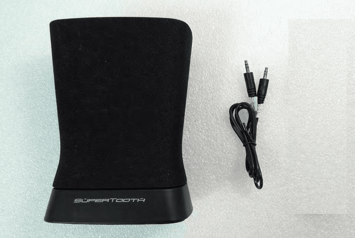
QVNBTD3
May 28, 2013BTD3
Equipment Class
DSS - Part 15 Spread Spectrum Transmitter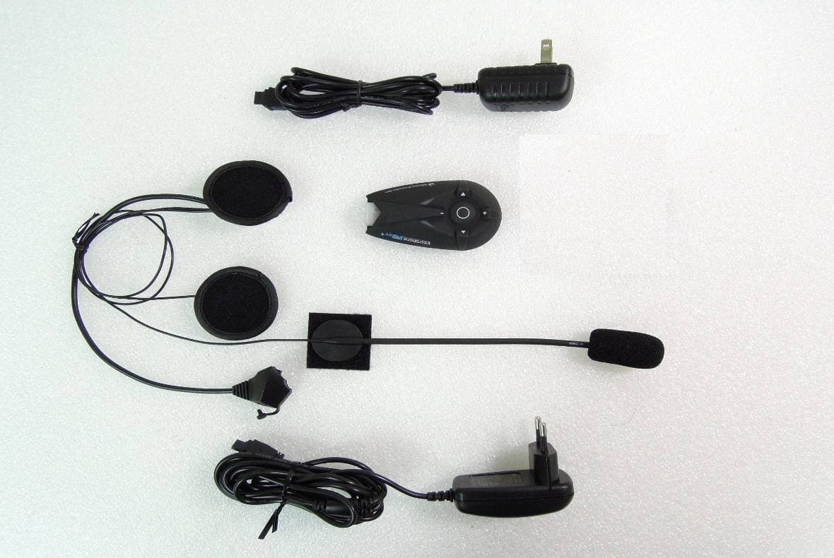
QVNBTF5XT
Mar 03, 2013BTF5XT
Equipment Class
DSS - Part 15 Spread Spectrum Transmitter