QVPWRH900Irrigation Control Remote Transmitter
Rain Bird Corporation - Controls Division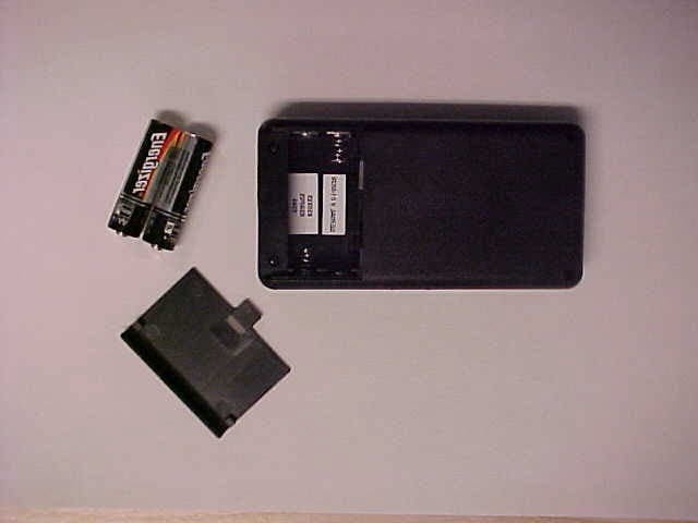
Click to zoom
Application Details
- Equipment Class
- DSC - Part 15 Security/Remote Control Transmitter
- Date of Grant
- Nov 20, 2003
- Application Purpose
- Original Equipment
- Date of Application
- Nov 20, 2003
- Equipment Note
- Irrigation Control Remote Transmitter
- Frequency Range
- 916.50000000 - 916.50000000
- Country
- United States
Documents & Files
Document Text
Text extracted from the exhibit documents filed with the FCC. Open a document above to read the original.
Users Manual
WIRELESS EAGLE ™ 500/700 SERIES ROTOR WIRELESS ROTOR HANDHELD WIRELESS ROTOR LISTENING DEVICE OPERATIONS MANUAL This device complies with part 15 of the FCC Rules. Operation is subject to the following two conditions: (1) This device may not cause harmful interference, and (2) This device must accept any interference received, including interference that may cause undesired operation. The term “IC:” before the certification/registration number only signifies that the Industry Canada Technical Specifications were met. P/N/ 63592211/03 Rain Bird Corporation Golf Division 6991 East Southpoint Rd, Building 1 Tucson, AZ 85706 USA Phone: (626) 812-3400 Fax: (626) 812-3411 Technical Assistance 1-800-984-2255 Page 1 TABLE OF CONTENTS DescriptionPage Introduction2 Maintenance3 Wireless Handheld4 Configure Key Function 6 Control Key Functions8 Unit Key Functions11 Rain Bird Messenger13 Listening Device17 Station Detail Configuration19 Page 2 INTRODUCTION New Paging Feature Simplifies Expansion Needs The Wireless Rotor from Rain Bird offers the following: • Quick and easy to retrofit or make additions to your course, even as an emergency replacement. • Reduced risk of collateral lightning damage. • No wire or satellite costs. • Reduces turf damage. • Easy conversion from a block system. The Rain Bird Wireless Rotor This unique rotor has an enclosed sealed-lead rechargeable battery. The battery level is maintained by the solar panel at the top of the rotor case. The battery is positioned in the enclosed compartment next to the communication board. Page 3 MAINTENANCE The Wireless EAGLE 500/700 series Rotor is an exclusive Closed-Case design. All of the superior characteristics of the EAGLE rotor are featured in this product, including the Rain Bird standard top- serviceable features. For performance data and maintenance information, please refer to the EAGLE Series Rotor catalog. Special screws have been used to assist in the prevention of theft and to maintain the integrity of the sealed battery/communication board. Please contact Rain Bird for assistance when the battery needs servicing or any troubleshooting is required. LED Diagnostics The Rotor enters a diagnostics mode following a successful configuration or by receiving a specific command from the Handheld Device. LED ActionState Description Stays on ContinuouslyBattery Level Too High Continuously FlashingBattery Level Good 2 Flashes then 3 sec delayBattery Level Low Always OFFSystem Shutdown 1 Flash then 3 sec delaySolar Panel Error Continuously FlashingSolar Panel Good Solar Panel Anti-theft screw Anti-theft screw LED Battery Communication Board (Clear plastic case used for illustration purposes only.) Page 5 Home – Main MenuKeypad Entering the Rotor ID To configure and control the Wireless Rotors, a logical address must be assigned to the rotor in the Handheld. This will be the same identification used in the Central Control Software. The Rotor ID consists of the hole #, the area handle, and the station. Both the hole # and the station entries are configured for two-digits. For example, hole #3 – rough - station 11 would be entered as 03311 as shown below: Page 4 THE WIRELESS HANDHELD DEVICE The Wireless Handheld Device provides operating capability in the field, performing a number of functions without having to send a page through the central control computer. Prior to being able to communicate with a Wireless Rotor using the Central Control, the Rotor must be configured With the Handheld Device. The Handheld Device is powered by two AA Batteries. To preserve the life of the batteries, several power management features have been implemented. If the Handheld Device remains idle for longer than 10 minutes, the unit will be shut off automatically. Additionally, the backlight feature of the LCD Display screen will only remain active for 10 minutes. After 10 minutes, the LCD Display screen will return to its normal mode of operation. To turn the Handheld Device on, momentarily press the F4 Function key. (Handheld may take up to 30 seconds to show the main menu.) To turn the Handheld Device off, momentarily press the F4 Function key from the Main Menu. Handheld Menu Structure Following is a graphical representation of the Menu Structure for the Handheld Device: Menu – Sub-Menu Off Send Time Home 1 2 2F4 F3 F2 F1 Enter Rotor ID Enter Rotor ID F4 F3 F2 F1 1 3 4 5 BLIT Time Menu Enter Config Data Setup Time Clear Rotor Database TableChg RotorOps PWR Ctrl Diag Unit Conf Ctrl MAIN MENU F1 – Menu F2 – Time (Shows current time/date set in the handheld) F3 – BLIT (Backlight) F4 – OFF F1 – Ctrl (Control) F2 – Conf (Configure) F3 – Unit F4 – Home (Returns to the main menu) 1.Enter “03”on the keypad for the hole #. 2.Once the hole number is entered, the numerical equivalent for each of the area handles will be displayed. Select the corresponding number on the keypad. 3.To complete, input the station number “11”and then press <enter> on the keypad Page 7 5. The Handheld is now ready to configure the Rotor. Once the “Activate Rotor With Magnet”screen appears, activate the rotor by passing a magnet across the LED display area of the Solar Panel. The magnet should pass over the LED once with the surface of the magnet slightly brushing along the top of the solar panel. Observe the flashing of the LED on the Solar Panel. Once the LED begins to flash approximately once every second, press the Prog <F3> key on the Handheld. After approximately 30 seconds, the solenoid should click twice to indicate that the Rotor has been successfully configured. 6. By default, the handheld will prompt for the next Rotor ID to be configured. To enter another Rotor ID, return to step 1 of this section. If finished, press the Home <F4> to return to the main menu. Page 6 CONFIGURING A ROTOR Prior to being able to perform any of the functions for Controlling a Rotor,the Rotor configuration data must be input into the Handheld and then transferred into the Rotor with the use of a magn…
Text truncated - open the document above for the full version.
Cover Letter(s)
Friday, November 21, 2003 Federal Communications Commission Authorization and Evaluation Division 7435 Oakland Mills Road Columbia, MD 21046 RE: Request for Confidentiality In reference to the application under FCC ID: QVPWRH900, and pursuant to Sections 0.457(d)(ii) and 0.459 of the Commission’s Rules, the Applicant hereby requests confidential treatment of the accompanying information as outlined below: Schematics Block diagram Theory of operations The above materials contain trade secrets and proprietary information not customarily released to the public. The public disclosure of these matters might be harmful to the Applicant and provide unjustified benefits to its competitors. The Applicant understands that pursuant to rule 0.457(d)(1)(ii), disclosure of this Application and all accompanying documentation will not be made before the date of the Grant for this application. Sincerely, Hiram Sanchez Q. A. Engineer Product Compliance & Reliability Controls Manufacturing Division Rain Bird Corporation Email: [email protected] 7590 Britannia Court San Diego, CA 92154 619-661-4416
Cover Letter(s)
1 Mike Kuo From: Mike Kuo Sent: November072003Friday 6:30 PM To: CLIENT ADVOCATES; Don Erwin Subject: RainBird Corporation- Controls Manufacturing Division, FCC ID:QVPWRH900, AN03T3336 Question #1: The information contains in the operational description also mentioned in the user manual. Based upon the information can be obtained from user manual, request for confidentiality on the operational description as submitted will not be granted. However, a detail technical description should be provided in the operational description to address section 15.231 periodical operation. From the user manual and the information provided, there is no technical information provided to demonstrate that this transmitter complies with periodical transmitter definition as stated in section 15.231 (a) (1) - (4). Please submit detail operational description. If the revised operational description contains technical information then such attachment can be granted as confidential document. Question #2: User manual does not contain information required under section 15.21 and 15.19(a)(3) of FCC rules. Please provide revised user manual. Question #3: Page 38 to Page 57 of test report listed different FCC ID number. Please make necessary correction. Question #4: Please remove schematic diagram and functional block diagram from the test report. Test report can not be granted for confidential document. Please do not include any confidential document inside the test report. Please submit revised test report. FYI: frequency stability test only requires for transmitter operates in 40.66-40.70MHz range. Best Regards Mike Kuo Compliance Certification Services 561F Monterey Road Morgan Hill CA 95037 Tel: (408)463-0885 x: 105 Fax: (408)463-0888 http://www.ccsemc.com
External Photos
REPORT: RV38111B FCC ID: QVPWRH900 7 2.7 Photographs of EUT - per 2.1033(b)(7) REPORT: RV38111B FCC ID: QVPWRH900 8 Photographs of EUT - per 2.1033(b)(7) continued REPORT: RV38111B FCC ID: QVPWRH900 9 Photographs of EUT - per 2.1033(b)(7) continued
ID Label/Location Info
REPORT: RV38111B FCC ID: QVPWRH900 34 4. LABELING REQUIREMENTS - PER 2.1033(B)(7) Label will be constructed of 0.02-inch plastic attached as shown on the equipment with permanent adhesive. All information on the label will be etched or screened. All methods will exceed the expected lifetime of the equipment. The label will be large enough to allow all information to be readily legible. 4.1 Additional Label Required Shown above is a copy of the label with the Part 15.19 Compliance Statement, Location of required information is checked “below”. The label will be placed in a conspicuous location on the device. 4.2 Photograph of Label Placement and Contents Because of the small size of this device the information in 4.1 may be placed in the documentation provided to the user. The FCC ID shall be placed upon the unit. This is in accordance with FCC Part 15.19 (a) (5). This device complies with Part 15 of the FCC Rules. Operation is subject to the following two conditions: (1) This device may not cause harmful interference, and (2) This device must accept any interference received, including interference that may cause undesired operation.
Internal Photos
REPORT: RV38111B FCC ID: QVPWRH900 10 Photographs of EUT - per 2.1033(b)(7) continued REPORT: RV38111B FCC ID: QVPWRH900 11 Photographs of EUT - per 2.1033(b)(7) continued REPORT: RV38111B FCC ID: QVPWRH900 12 Photographs of EUT - per 2.1033(b)(7) continued REPORT: RV38111B FCC ID: QVPWRH900 13 Photographs of EUT - per 2.1033(b)(7) continued REPORT: RV38111B FCC ID: QVPWRH900 14 Photographs of EUT - per 2.1033(b)(7) continued REPORT: RV38111B FCC ID: QVPWRH900 15 Photographs of EUT - per 2.1033(b)(7) continued REPORT: RV38111B FCC ID: QVPWRH900 16 Photographs of EUT - per 2.1033(b)(7) continued REPORT: RV38111B FCC ID: QVPWRH900 17 Photographs of EUT - per 2.1033(b)(7) continued REPORT: RV38111B FCC ID: QVPWRH900 18 Photographs of EUT - per 2.1033(b)(7) continued REPORT: RV38111B FCC ID: QVPWRH900 19 Photographs of EUT - per 2.1033(b)(7) continued REPORT: RV38111B FCC ID: QVPWRH900 20 Photographs of EUT - per 2.1033(b)(7) continued REPORT: RV38111B FCC ID: QVPWRH900 21 Photographs of EUT - per 2.1033(b)(7) continued
Test Report
REPORT: RV38111B FCC ID: QVPWRH900 1 CERTIFICATION FOR INTENTIONAL RADIATOR per Part 15 Subpart C (CFR 47, 15.201, - 15.209 &15.231) Irrigation Control Transmitter Model No. WRH900 916.5 MHz PREPARED FOR APPLICANT: RainBird Corporation 7590 Britannia Court San Diego, CA 92154 FRN: 0008350290 PREPARED BY: DNB ENGINEERING, INC. 5969 Robinson Avenue Riverside, CA 92503-8620 (909) 637-2630 ENGINEERING, INC. REPORT: RV38111B FCC ID: QVPWRH900 2 TRANSMITTAL SUMMARY Unit tested: Irrigation Control Remote Transmitter Model #: WRH900 FCC ID: QVPWRH900 Specifications: ANSI C63.4 1992 and CFR 47 FCC part 15 Subpart C Purpose of Report: This report was prepared to document the status of the Irrigation Control RemoteTransmitter (916 MHz) with requirements of the standards listed above. Requirements not applicable to EUT Part 15.37 - Not applicable Emergency Broadcast System - Not applicable Spread Spectrum Exhibit - Not applicable Scanning Receiver - Not applicable Test Summary The EUT’s compliance status according to the tests performed is as follows. REQUIREMENTS STATUS FCC part 15 Subpart C per 15.201-, 15.209 & 15.231 COMPLIANT The report shall not be reproduced, except in full, without the written approval of DNB ENGINEERING, INC. Results contained in this report relate only to the item tested. The Irrigation Control Remote Transmitter M/N WRH900 met all the criteria pertaining to standards called out for testing. REPORT: RV38111B FCC ID: QVPWRH900 3 TABLE OF CONTENTS Section Title Page # 1.0 Administration Data 4 1.1.1 Request for Certification 5 1.2 Related Submittals/Grants 5 1.3 Purpose of Test 5 2.0 Test Description 6 2.1 Test Configuration 6 2.2 Equipment Description 6 2.3 Mode of Operation 6 2.4 Antenna Requirements 6 2.5 Circuit Description 6 2.6 Schematics 6 2.7 Photographs of EUT 7 - 21 3.0 Emissions 22 3.1 Radiated Emissions Test Setup and Procedure 22 3.1.1 Spurious Radiation Test Site 22 – 23 3.1.2 Example of Calculation 24 3.1.3 Field Strength of Fundamental 24 3.1.4 Harmonic Radiated Emissions 24 3.1.5 Spurious Emissions Not Associated with Fundamental 24 3.1.6 Duty Cycle Correction 27 Plots for Duty cycle 28 – 29 3.1.7 Occupied Bandwidth 30 Plots for Occupied Bandwidth 31 3.1.8 Photographs of Radiated Test Setup 32 Measurement of Frequency Stability 33 4.0 Label Requirements 34 4.1 Addition Label Required 34 4.2 Photograph of Label Placement and Contents 34 5.0 Schematics 35 Uncertainty Tolerance 36 Information Pertaining to Equipment Manufactured After Compliance Testing 37 Test Equipment Log 38 Appendix A Owners Manual 39 – 58 REPORT: RV38111B FCC ID: QVPWRH900 4 1.0 ADMINISTRATIVE DATA Certifications and Qualifications I certify that DNB Engineering, Inc conducted the tests performed in order to obtain the technical data presented in this application. Also, based on the results of the enclosed data, I have concluded that the equipment tested meets or exceeds the requirements of the Rules and Regulations governing this application. Measurement Repeatability Information The test data presented in this report has been acquired using the guidelines set forth in FCC Part 15 Subpart C (CFR 47, 15.201 – 15.209 and 15.231). The test results presented in this document are valid only for the equipment identified herein under the test conditions described. Repeatability of these test results will only be achieved with identical measurement conditions. These conditions include: The same test distance, EUT Height, Measurement Site Characteristics, and the same EUT System Components. The system must have the same Interconnecting Cables arranged in identical placement to that in the test set-up, with the system and/or EUT functioning in the identical mode of operation (i.e. software and so on) as on the date of the test. Any deviation from the test conditions and the environment on the date of the test may result in measurement repeatability difficulties. All changes made to the EUT during the course of testing as identified in this test report must be incorporated into the EUT or identical models to ensure compliance with the FCC regulations. C. L. Payne III (Para. 1.1) Manager, Test Dept. DNB Engineering, Inc. (Riverside Facility) Tel. (909) 637-2630 FAX (909) 637-2704 E-mail: [email protected] REPORT: RV38111B FCC ID: QVPWRH900 5 1.1.1 Request for Certification Per 2.1033(b)1: Applicant: Rain Bird Corporation 7590 Britannia Court San Diego, CA 92154 FRN: 0008350290 Contact: Hiram Sanchez Phone: (619) 661-4416 Equipment Under Test: Irrigation Control Remote Transmitter FCC ID: QVPWRH900 1.2 Related Submittals/Grants None. 1.3 Purpose of Tests The purpose of this series of tests was to demonstrate the Electromagnetic Compatibility (EMC) characteristics of the EUT. The following tests were performed: REQUIREMENTS STATUS FCC part 15 Subpart C Per 15.201- 15.209 &15.231 COMPLIANT REPORT: RV38111B FCC ID: QVPWRH900 6 2. TEST DESCRIPTION 2.1 Test Configuration Configuration Unit Name - Processor, Monitor Printer, Cable, etc. (indent for features of a unit) Style/Model/ Part No. Comments/ FCC ID# A Irrigation Control Remote (916 MHz) WRH900 QVPWRH900 2.2 Equipment Description Please see Appendix A 2.3 Mode of Operation EUT was placed in three orthogonal positions to determine worst case emissions. Fresh batteries were used for final measurements. 2.4 Antenna Requirement - per 15.203 The antenna is internally fixed. 2.5 Circuit Description - per 2.1033(b)4 Please see Owners Manual – Appendix A 2.6 Schematics Please see Section 5 REPORT: RV38111B FCC ID: QVPWRH900 7 2.7 Photographs of EUT - per 2.1033(b)(7) REPORT: RV38111B FCC ID: QVPWRH900 8 Photographs of EUT - per 2.1033(b)(7) continued REPORT: RV38111B FCC ID: QVPWRH900 9 Photographs of EUT - per 2.1033(b)(7) continued REPORT: RV38111B FCC ID: QVPWRH900 10 Photographs of EUT - per 2.1033(b)(7) continued REPORT: RV38111B FCC ID: QVPWRH900 11 Photographs of EUT - per 2.1033(b)(7) continued REPORT: RV38111B FCC ID: QVPWRH900 12 Photographs of EUT…
Text truncated - open the document above for the full version.
Test Setup Photos
REPORT: RV38111B FCC ID: QVPWRH900 32 3.1.8 Photographs of Radiated Test Setup – per 2.1033(b)(7) Radiated Emissions
Contact Information
Applicant
Michael Roberts(Director)
Test Firm
DNB Engineering, Inc.Mike Neis
Technical Specifications
| # | Rule Parts | Frequency Range | Power Output |
|---|---|---|---|
| 1 | 15.231 | 916.5 MHz - 916.5 MHz | - |
Other Applications from Rain Bird Corporation - Controls Division
QVP001BAT
Jan 16, 2024Lawn Sprinkler Control
Equipment Class
DTS - Digital Transmission System
QVPWST
Nov 20, 2003Wireless Rain Sensor
Equipment Class
DSC - Part 15 Security/Remote Control Transmitter