QVPWSTWireless Rain Sensor
Rain Bird Corporation - Controls Division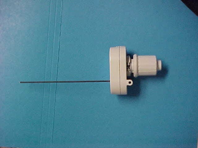
Click to zoom
Application Details
- Equipment Class
- DSC - Part 15 Security/Remote Control Transmitter
- Date of Grant
- Nov 20, 2003
- Application Purpose
- Original Equipment
- Date of Application
- Nov 20, 2003
- Equipment Note
- Wireless Rain Sensor
- Frequency Range
- 433.92000000 - 433.92000000
- Country
- United States
Documents & Files
Document Text
Text extracted from the exhibit documents filed with the FCC. Open a document above to read the original.
Users Manual
Rain Bird Sales, Inc Commercial Division 6640 S. Bonney Avenue Tucson, AZ 85706 USA Phone: (520) 434-6200 Fax: (520) 434-6246 Specification Hotline (USA and Canada only): 1-800-458-3005 Rain Bird Sales, Inc Contractor Division 970 West Sierra Madre Avenue Azusa, CA 91702 USA Phone: (626) 812-3400 Fax: (626) 812-3411 Technical Assistance (USA and Canada only): 1-800-247-3782 Wireless Rain and Wireless Rain/Freeze Sensor Installation and Operating Instructions for: WRC: Wireless Rain Sensor Combo WRT: Wireless Rain Sensor Transmitter WSR: Wireless Rain Sensor Receiver WRFC: Wireless Rain and Freeze Sensor Combo WRFT: Wireless Rain and Freeze Sensor Transmitter 7/03 635927 Wireless Rain and Freeze Sensor Wiring Important! Before connecting wires, you must determine whether your controller uses “Normally Open” or “Normally Closed” wiring for sensors. All Rain Bird controllers, and most other manufacturers’ controllers, are installed using a “Normally Closed” wiring method. Normally Closed Installation Note:The lead wire labeled “NO” is not used with this installation method. Controllers With Sensor Input Many modern controllers (such as Rain Bird’s E Class, ESP-LX+, and ESP-MC) include built-in terminals for sensor input. Dedicated terminals are usually labeled “sensor” or “SN” on the controller’s terminal strip.See Illustration 3. 1. Connect the Red and Black leads to the two 24VAC terminals on your controller. (It is not important which wire goes to which terminal.) 2. To connect the Rain and Freeze Sensor, remove the jumper wire (if present) from the controller’s sensor terminals. 3. Connect the Green lead and the Brown lead to the Sensor Terminals on your controller. Controllers Without Sensor Input Use the procedure below if your controller does NOT have dedicated sensor terminals.See Illustration 4. 1. Connect the Red and Black leads to the 24 VAC terminals on your controller. 2. Disconnect the valve common wire from the common terminal (“C” or “COM”) on the controller’s terminal strip. Connect the valve common wire to the green lead on the Sensor Receiver. 3. Connect the Brown lead to the “COM” terminal on the controller’s terminal strip. Normally Open Installation Some non-Rain Bird controllers require rain sensors to be installed “Normally Open” (“NO”). In this case, substitute the White Lead for the Brown Lead in the installation for a “Normally Closed” (“NC”) installation (above). Be sure to consult with the controller manufacturer’s manual to determine the appropriate procedure for connecting the Rain Sensor to your controller. Note: In this case, the brown wire will not be used. WRS-100 Wireless Rain Sensor2 Wireless Rain and Freeze Sensor The Wireless Rain Sensor automatically monitors rainfall and shuts off your sprinklers to prevent unnecessary watering. Rain/Freeze Transmitter will also prevent watering in freezing conditions. Note:The Wireless Rain Sensor is a low-voltage device compatible with all 24 volt alternating current (VAC) control circuits and 24 VAC pump start relays. The Wireless Rain and Freeze Sensor is a very sophisticated Sensor Transmitter and Receiver system designed to work with all 24 volt alternating current (VAC) control circuits and 24 VAC pump start relay circuits. The Receiver has three Light Emitting Diodes (LEDs). Each LED can indicate two conditions. If the LED is solid then the condition labeled on the left is occurring. If the LED is blinking the condition labeled on the right has taken place. These are explained on page 7. 1. Installation Note:Follow the installation instructions carefully and install the unit only in full compliance with the National Electrical Code (NEC) or your local electrical code. There are two components of the Wireless Rain Sensor product, the Sensor Transmitter and the Receiver. Important!:Begin by installing the Receiver and test the two components (transmitter and receiver) side by side before mounting the Sensor Transmitter. Wireless Rain and Freeze Sensor Receiver Mounting 1. Select a place near your controller where you will install the Receiver. Ensure that there will be room for the receiver antenna and that the leads will reach to the sensor connection on your controller (approximately 24 inches). Note:The Receiver unit is weather resistant and is suitable for mounting near an outdoor controller. 2. Secure the bracket to the wall near your controller with appropriate fasteners. Be sure to install the bracket with the flanges facing out away from the wall.See Illustration 1. 3. Slide the water resistant receiver unit down onto the mounting bracket. See Illustration 2. 4. Attach the red “Notice” sticker to your automated irrigation system control panel. 5. Attach the gray “Receiver” memory sticker to the side of the Receiver. 1WRS Wireless Rain and Freeze Sensor 1 Mount Receiver bracket near existing controller. 2 Slide Receiver down on to the mounting bracket. Receiver Memory Record Install bracket with flanges facing out from the wall. COM 123MV SENSOR TRANSFORMER SENSOR GND 24V 24V RED BLACK GREEN BROWN ORANGE ORANGE TO RECEIVE R 3 4 Testing the Transmitter and Receiver Pair If you bought the Transmitter and Receiver together, they were programmed at the factory to work together. If you purchased them separately, or, if the following test procedure doesn’t work properly, it may be necessary to program the receiver to work with the transmitter. Use the following procedure to test the two units together.See Illustration 5. 1. Push and hold the pin for a few seconds on the top of the Sensor Transmitter. 2. If the Receiver detects the signal, the Red LED will begin to indicate “Watering Suspended”. 3. You can release the Transmit button and continue with the installation. SENSOR BYPASS Watering Suspended WATERING SUSPENDED BY SENSOR 5 Test Sensor Transmitter with Receiver Select an appropriate mounting location as described above. Drive two mounting screws through the mounting holes in the mounting bracket. Use fa…
Text truncated - open the document above for the full version.
Cover Letter(s)
Friday, November 21, 2003 Federal Communications Commission Authorization and Evaluation Division 7435 Oakland Mills Road Columbia, MD 21046 RE: Request for Confidentiality In reference to the application under FCC ID: QVPWST, and pursuant to Sections 0.457(d)(ii) and 0.459 of the Commission’s Rules, the Applicant hereby requests confidential treatment of the accompanying information as outlined below: Schematics Block diagram Theory of operations The above materials contain trade secrets and proprietary information not customarily released to the public. The public disclosure of these matters might be harmful to the Applicant and provide unjustified benefits to its competitors. The Applicant understands that pursuant to rule 0.457(d)(1)(ii), disclosure of this Application and all accompanying documentation will not be made before the date of the Grant for this application. Sincerely, Hiram Sanchez Q. A. Engineer Product Compliance & Reliability Controls Manufacturing Division Rain Bird Corporation Email: [email protected] 7590 Britannia Court San Diego, CA 92154 619-661-4416
Cover Letter(s)
Assessment AN03T3337 Application T11369.txt From: Les Payne [[email protected]] Sent: November18 2003 Tuesday 5:32 PM To: Mike Kuo Cc: Dean Thornton Subject: Assessment AN03T3337 Application T11369 Greetings Mike, Sorry for the confusion. I could not find in the report where you weere referencing an "Average" measurement. After reviewing with Dean Thorton at Rain Bird we noticed in one of my embedded graphics the error in the "MD" column of the test report indicating "AV" when it should have indicated "PK". This has been corrected and a new report has been attached. Les Payne DNB Engineering 5969 Robinson Avenue Riverside, CA 92503-8620 (909) 637-2630 (909) 637-2704 [email protected] www.dnbenginc.com -----Original Message----- From: Les Payne [mailto:[email protected]] Sent: Tuesday, November 18, 2003 4:06 PM To: Mike Kuo Subject: RE: Rainbird Corporation- Controls Manufacturing Division, FCC ID :QVPWST, AN03T3337 We did not use average detector measurements, perhaps I have an error in my data sheets that indicates this. Please let me know wherre I have indicated average measurements. My repsonse was intended to indicate that where average detector measurements where acceptable that is the method used, wher4e peak detector measurements where acceptable that is what we used. We have a new report writer and it could be that there is an error in the report that needs to be corrected. Sorry for the confusion. I believe this is a simple documentation error do you think we can issue grant and solve in the next day or two. Les -----Original Message----- From: Mike Kuo [mailto:[email protected]] Sent: Tuesday, November 18, 2003 3:40 PM To: 'Les Payne'; Mike Kuo Cc: Dean Thornton Subject: RE: Rainbird Corporation- Controls Manufacturing Division, FCC ID :QVPWST, AN03T3337 Hi Les : Your reply to Question #5: When the device is using pulse modulation, you can not use average detector to make the average measurement. You should use peak detector and correct the peak reading with duty cycle factor to obtain the average reading. Attached please find the Duty cycle discuss Page 1 Assessment AN03T3337 Application T11369.txt from FCC for your reference. Question #5 has not been addressed at this point. Best Regards Mike Kuo -----Original Message----- From: Les Payne [mailto:[email protected]] Sent: Tuesday, November 18, 2003 3:34 PM To: Mike Kuo Cc: Dean Thornton Subject: RE: Rainbird Corporation- Controls Manufacturing Division, FCC ID :QVPWST, AN03T3337 Mike, With regards to Item number 5. The Duty cycle measurements were calculated using peak measurments not average measurements. Plots in report are peak. Acctusal radiated field measurements are average. Do you require anytinhg else to clears this application. Les -----Original Message----- From: Thornton, Dean CLE 2626 [mailto:[email protected]] Sent: Tuesday, November 18, 2003 3:19 PM To: [email protected] Subject: FW: Rainbird Corporation- Controls Manufacturing Division, FCC ID :QVPWST, AN03T3337 -----Original Message----- From: Mike Kuo [mailto:[email protected]] Sent: Monday, November 10, 2003 2:47 PM To: '[email protected]' Subject: FW: Rainbird Corporation- Controls Manufacturing Division, FCC ID :QVPWST, AN03T3337 > -----Original Message----- > From: Mike Kuo > Sent:Friday, November 07, 2003 5:46 PM > To:CLIENT ADVOCATES; Don Erwin > Subject:Rainbird Corporation- Controls Manufacturing Division, FCC > ID:QVPWST, AN03T3337 > > Question #1: The information contains in the operational description also > mentioned in the user manual. Based upon the information can be obtained > from user manual, request for confidentiality on the operational > description as submitted will not be granted. However, a detail technical > description should be provided in the operational description to address > section 15.231 periodical operation. From the user manual and the > information provided, there is no technical information provided to > demonstrate that this transmitter complies with periodical transmitter Page 2 Assessment AN03T3337 Application T11369.txt > definition as stated in section 15.231 (a) (1) - (4). Please submit > detail operational description. If the revised operational description > contains technical information then such attachment can be granted as > confidential document. > > Question #2: User manual does not contain information required under > section 15.21 of FCC rules. Please provide revised user manual. > > Question #3: Page 31 to Page 39 of test report listed different FCC ID > number. Please make necessary correction. > > Question #4: Please remove schematic diagram and functional block diagram > from the test report. Test report can not be granted for confidential > document. Please do not include any confidential document inside the test > report. Please submit revised test report. > > Question #5: Per section 15.231 (b) (2) when average measurements are > employed, the provisions in section 15.35 for averaging pulsed emissions > and for limiting peak emissions apply. In the test report, only average > readings are provided. Please provide peak reading. > > FYI: frequency stability test only requires for transmitter operates in > 40.66-40.70MHz range. > > > > Best Regards > > Mike Kuo > Compliance Certification Services > 561F Monterey Road > Morgan Hill CA 95037 > Tel: (408)463-0885 x: 105 > Fax: (408)463-0888 > http://www.ccsemc.com > Page 3
External Photos
REPORT: RV48030B FCC ID: QVPWST 7 2.7 Photographs of EUT - per 2.1033(b)(7) REPORT: RV48030B FCC ID: QVPWST 8 Photographs of EUT - per 2.1033(b)(7) continued
Internal Photos
REPORT: RV48030B FCC ID: QVPWST 9 Photographs of EUT - per 2.1033(b)(7) continued REPORT: RV48030B FCC ID: QVPWST 10 Photographs of EUT - per 2.1033(b)(7) continued REPORT: RV48030B FCC ID: QVPWST 11 Photographs of EUT - per 2.1033(b)(7) continued REPORT: RV48030B FCC ID: QVPWST 12 Photographs of EUT - per 2.1033(b)(7) continued REPORT: RV48030B FCC ID: QVPWST 13 Photographs of EUT - per 2.1033(b)(7) continued REPORT: RV48030B FCC ID: QVPWST 14 Photographs of EUT - per 2.1033(b)(7) continued
Test Report
REPORT: RV48030B FCC ID: QVPWST 1 CERTIFICATION FOR INTENTIONAL RADIATOR per Part 15 Subpart C (CFR 47, 15.201, - 15.209 &15.231) Irrigation Control Transmitter Model No. WST 434 MHz PREPARED FOR APPLICANT: RainBird Corporation 7590 Britannia Court San Diego, CA 92154 FRN: 0008350290 PREPARED BY: DNB ENGINEERING, INC. 5969 Robinson Avenue Riverside, CA 92503-8620 (909) 637-2630 ENGINEERING, INC. REPORT: RV48030B FCC ID: QVPWST 2 TRANSMITTAL SUMMARY Unit tested: Irrigation Control Remote Transmitter Model #: WST FCC ID: QVPWST Specifications: ANSI C63.4 1992 and CFR 47 FCC part 15 Subpart C Purpose of Report: This report was prepared to document the status of the Irrigation Control RemoteTransmitter (434 MHz) with requirements of the standards listed above. Requirements not applicable to EUT Part 15.37 - Not applicable Emergency Broadcast System - Not applicable Spread Spectrum Exhibit - Not applicable Scanning Receiver - Not applicable Test Summary The EUT’s compliance status according to the tests performed is as follows. REQUIREMENTS STATUS FCC part 15 Subpart C per 15.201-, 15.209 & 15.231 COMPLIANT The report shall not be reproduced, except in full, without the written approval of DNB ENGINEERING, INC. Results contained in this report relate only to the item tested. The Irrigation Control Remote Transmitter M/N WST met all the criteria pertaining to standards called out for testing. REPORT: RV48030B FCC ID: QVPWST 3 TABLE OF CONTENTS Section Title Page # 1.0 Administration Data 4 1.1.1 Request for Certification 5 1.2 Related Submittals/Grants 5 1.3 Purpose of Test 5 2.0 Test Description 6 2.1 Test Configuration 6 2.2 Equipment Description 6 2.3 Mode of Operation 6 2.4 Antenna Requirements 6 2.5 Circuit Description 6 2.6 Schematics 6 2.7 Photographs of EUT 7 - 14 3.0 Emissions 15 3.1 Radiated Emissions Test Setup and Procedure 15 3.1.1 Spurious Radiation Test Site 15 – 16 3.1.2 Example of Calculation 17 3.1.3 Field Strength of Fundamental 17-18 3.1.4 Harmonic Radiated Emissions 17-18 3.1.5 Spurious Emissions Not Associated with Fundamental 17-19 3.1.6 Duty Cycle Correction 20 Plots for Duty cycle 20 – 22 3.1.7 Occupied Bandwidth 23 Plots for Occupied Bandwidth 24 3.1.8 Photographs of Radiated Test Setup 25 Measurement of Frequency Stability 26 4.0 Label Requirements 27 4.1 Addition Label Required 27 4.2 Photograph of Label Placement and Contents 27 5.0 Schematics 28 Uncertainty Tolerance 29 Information Pertaining to Equipment Manufactured After Compliance Testing 30 Test Equipment Log 31 Appendix A Owners Manual 32 – 39 REPORT: RV48030B FCC ID: QVPWST 4 1.0 ADMINISTRATIVE DATA Certifications and Qualifications I certify that DNB Engineering, Inc conducted the tests performed in order to obtain the technical data presented in this application. Also, based on the results of the enclosed data, I have concluded that the equipment tested meets or exceeds the requirements of the Rules and Regulations governing this application. Measurement Repeatability Information The test data presented in this report has been acquired using the guidelines set forth in FCC Part 15 Subpart C (CFR 47, 15.201 – 15.209 and 15.231). The test results presented in this document are valid only for the equipment identified herein under the test conditions described. Repeatability of these test results will only be achieved with identical measurement conditions. These conditions include: The same test distance, EUT Height, Measurement Site Characteristics, and the same EUT System Components. The system must have the same Interconnecting Cables arranged in identical placement to that in the test set-up, with the system and/or EUT functioning in the identical mode of operation (i.e. software and so on) as on the date of the test. Any deviation from the test conditions and the environment on the date of the test may result in measurement repeatability difficulties. All changes made to the EUT during the course of testing as identified in this test report must be incorporated into the EUT or identical models to ensure compliance with the FCC regulations. C. L. Payne III (Para. 1.1) Manager, Test Dept. DNB Engineering, Inc. (Riverside Facility) Tel. (909) 637-2630 FAX (909) 637-2704 E-mail: [email protected] REPORT: RV48030B FCC ID: QVPWST 5 1.1.1 Request for Certification Per 2.1033(b)1: Applicant: Rain Bird Corporation 7590 Britannia Court San Diego, CA 92154 FRN: 0008350290 Contact: Hiram Sanchez Phone: (619) 661-4416 Equipment Under Test: Irrigation Control Remote Transmitter FCC ID: QVPWST 1.2 Related Submittals/Grants None. 1.3 Purpose of Tests The purpose of this series of tests was to demonstrate the Electromagnetic Compatibility (EMC) characteristics of the EUT. The following tests were performed: REQUIREMENTS STATUS FCC part 15 Subpart C Per 15.201- 15.209 &15.231 COMPLIANT REPORT: RV48030B FCC ID: QVPWST 6 2. TEST DESCRIPTION 2.1 Test Configuration Configuration Unit Name - Processor, Monitor Printer, Cable, etc. (indent for features of a unit) Style/Model/ Part No. Comments/ FCC ID# A Irrigation Control Remote (434 MHz) WST QVPWST 2.2 Equipment Description Please see Appendix A 2.3 Mode of Operation EUT was placed in three orthogonal positions to determine worst case emissions. Fresh batteries were used for final measurements. 2.4 Antenna Requirement - per 15.203 The antenna is internally fixed. 2.5 Circuit Description - per 2.1033(b)4 Please see Owners Manual – Appendix A 2.6 Schematics Please see Section 5 REPORT: RV48030B FCC ID: QVPWST 7 2.7 Photographs of EUT - per 2.1033(b)(7) REPORT: RV48030B FCC ID: QVPWST 8 Photographs of EUT - per 2.1033(b)(7) continued REPORT: RV48030B FCC ID: QVPWST 9 Photographs of EUT - per 2.1033(b)(7) continued REPORT: RV48030B FCC ID: QVPWST 10 Photographs of EUT - per 2.1033(b)(7) continued REPORT: RV48030B FCC ID: QVPWST 11 Photographs of EUT - per 2.1033(b)(7) continued REPORT: RV48030B FCC ID: QVPWST 12 Photographs of EUT - per 2.1033(b)(7) continued REPORT: RV48030B FCC…
Text truncated - open the document above for the full version.
Test Setup Photos
REPORT: RV48030B FCC ID: QVPWST 25 3.1.8 Photographs of Radiated Test Setup – per 2.1033(b)(7) Radiated Emissions
Contact Information
Applicant
Michael Roberts(Director)
Test Firm
DNB Engineering, Inc.Mike Neis
Technical Specifications
| # | Rule Parts | Frequency Range | Power Output |
|---|---|---|---|
| 1 | 15.231 | 433.92 MHz - 433.92 MHz | - |
Other Applications from Rain Bird Corporation - Controls Division
QVP001BAT
Jan 16, 2024Lawn Sprinkler Control
Equipment Class
DTS - Digital Transmission System
QVPWRH900
Nov 20, 2003Irrigation Control Remote Transmitter
Equipment Class
DSC - Part 15 Security/Remote Control Transmitter