QWHDW20RWireless Systems
Music Tribe Commercial MY Sdn. Bhd.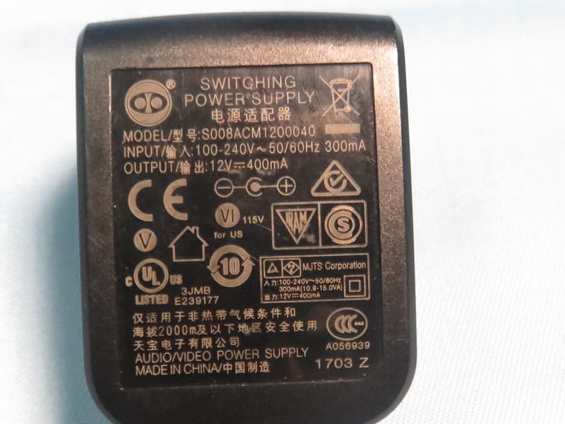
Click to zoom
Application Details
- Equipment Class
- DTS - Digital Transmission System
- Date of Grant
- Jul 07, 2020
- Application Purpose
- Original Equipment
- Date of Application
- Jul 07, 2020
- Equipment Note
- Wireless Systems
- Frequency Range
- 2406.00000000 - 2475.00000000
- Country
- Malaysia
Documents & Files
Document Text
Text extracted from the exhibit documents filed with the FCC. Open a document above to read the original.
Users Manual
Getting Started 1. Connect the DW 20T inputs to an original audio source such as a mixer or media player, then connect the outputs of the DW 20R to a destination such as a mixer, amplifier, or active speaker. Leave the amp or speakers turned off for now. 2.Connect the power adapters to each unit. They will power on automatically and their PAIR buttons will blink slowly to indicate standby mode. 3.Press and hold the PAIR button on the DW 20T for 4 seconds. The LED ring will flash rapidly to indicate that it is trying to pair, and will continue trying for up to 30 seconds. 4.Within 30 seconds of initiating the DW 20T for pairing, press and hold the PAIR button on the DW 20R for 4 seconds as well. Its LED ring will flash rapidly. 5. When successfully paired, the LED rings on both the 20T and 20R will light solid (not flashing). If either unit’s LED ring flashes slowly, this indicates that pairing was unsuccessful. Make sure both units are free of obstructions and are within 100 feet / 30 meters of each other. 6.After all audio and power connections have been made, power on the amplifier or active speakers. Pairing multiple DW 20R units with a DW 20T 1. Connect the DW 20T and the first DW 20R as described in ‘Getting Started’ (hold each PAIR button for 4 seconds). 2.On the second DW 20R unit, hold the PAIR button for 4 seconds to activate pairing, then let it search for 30 seconds. The pairing function will time out after 30 seconds and the LED will blink slowly. 3.Press the DW 20T PAIR button for 4 seconds, and then press the second DW 20R unit’s PAIR button for 4 seconds. Both DW 20R units will now be connected to the same DW 20T. 4.Note - holding the PAIR button for 10 seconds on the DW 20T will clear the memory of connected DW 20R units. (1) PAIR button enables the unit to become available for pairing by pressing and holding for 4 seconds. The LED ring will indicate the current status. See the Getting Started section for details. (2) LEVEL knob adjusts the volume of the signal sent to the output jacks. (3) SIGNAL LEDs light when the DW 20R receives an audio signal from the DW 20T. (4) DC INPUT socket accepts the included power adapter. (5) STEREO/MONO switch determines whether the outgoing wireless audio signal is stereo or mono. (6) LEVEL knob adjusts the sensitivity of the inputs. (7) SIGNAL LEDs light green when signal is present at the inputs. The LEDs light red when the incoming audio signal clips the inputs. If this happens, lower the output level of the source audio. (8) OUTPUT jacks send a line-level audio signal to another audio device (mixer, amplifier, etc.) via balanced XLR or unbalanced ¼" TS cables. (9) INPUT jacks accept audio signals via balanced XLR or unbalanced ¼" TS cables. AIR LINK DW 20R/DW 20T 2.4 GHz Wireless Stereo Receiver/Transmitter for High-Performance Stereo Audio Broadcasting (1)(2)(4)(3) (8)(9) (1)(6)(4)(7) (5) Specifications LEGAL DISCLAIMER MUSIC Tribe accepts no liability for any loss which may be suffered by any person who relies either wholly or in part upon any description, photograph, or statement contained herein. Technical specifications, appearances and other information are subject to change without notice. All trademarks are the property of their respective owners. MIDAS, KLARK TEKNIK, LAB GRUPPEN, LAKE, TANNOY, TURBOSOUND, TC ELECTRONIC, TC HELICON, BEHRINGER, BUGERA and COOLAUDIO are trademarks or registered trademarks of MUSIC Tribe Global Brands Ltd. © MUSIC Tribe Global Brands Ltd. 2018 All rights reserved. LIMITED WARRANTY For the applicable warranty terms and conditions and additional information regarding MUSIC Tribe’s Limited Warranty, please see complete details online at musictri.be/warranty. FEDERAL COMMUNICATIONS COMMISSION COMPLIANCE INFORMATION Responsible Party Name: MUSIC Tribe Commercial NV Inc. Address: 5270 Procyon Street Las Vegas, NV 89118 USA Phone Number: +1 702 800 8290 AIR LINK DW 20R/DW 20T complies with the FCC rules as mentioned in the following paragraph: This equipment has been tested and found to comply with the limits for a Class B digital device, pursuant to part 15 of the FCC Rules. These limits are designed to provide reasonable protection against harmful interference in a residential installation. This equipment generates, uses and can radiate radio frequency energy and, if not installed and used in accordance with the instructions, may cause harmful interference to radio communications. However, there is no guarantee that interference will not occur in a particular installation. If this equipment does cause harmful interference to radio or television reception, which can be determined by turning the equipment off and on, the user is encouraged to try to correct the interference by one or more of the following measures: • Reorient or relocate the receiving antenna. • Increase the separation between the equipment and receiver. • Connect the equipment into an outlet on a circuit different from that to which the receiver is connected. • Consult the dealer or an experienced radio/TV technician for help. This equipment complies with Part 15 of the FCC Rules. Operation is subject to the following two conditions: (1) This device may not cause harmful interference, and (2) This device must accept any interference received, including interference that may cause undesired operation. FCC ID: QWHDW20T This transmitter must not be co-located or operating in conjunction with any other antenna or transmitter. Caution! The MUSIC Tribe is not responsible for any radio or TV interference caused by unauthorized modifications to this equipment. Such modifications could void the user authority to operate the equipment FCC RF Radiation Exposure Statement: (1) This Transmitter must not be co-located or operating in conjunction with any other antenna or transmitter. (2) This equipment complies with FCC RF radiation exposure limits set forth for an uncontrolled environment. This equipment should be installed and operated with a mini…
Text truncated - open the document above for the full version.
External Photos
Report No.: 1712C210B Page 2 of 10 Report No.: 1712C210B Page 3 of 10 Report No.: 1712C210B Page 4 of 10 Group 1 Antenna Group 2 Antenna Report No.: 1712C210B Page 5 of 10 Adapter: S008ACM1200040 Report No.: 1712C210B Page 6 of 10 Report No.: 1712C210B Page 7 of 10 Adapter: GPE053A-V120040-Z Report No.: 1712C210B Page 8 of 10
Internal Photos
Report No.: 1712C210B Page 9 of 10 Report No.: 1712C210B Page 10 of 10
RF Exposure Info
Report No.: BTL-FCCP-2-1712C210B Page 1 of 4 FCC RF EXPOSURE REPORT FCC ID: QWHDW20R Project No. : 1712C210B Equipment : Wireless Systems Brand Name : KLARK TEKNIK Test Model : DW 20R Series Model : N/A Applicant : MUSIC Tribe Manufacturing PH Ltd. Address : 17A Brunswick Street Hamilton HM 10 Bermuda Manufacturer : MUSIC Tribe Manufacturing PH Ltd. Address : 17A Brunswick Street Hamilton HM 10 Bermuda Factory : Zhongshan Eurotec Electronics Ltd. Address : No.10 Wanmei Road, South China Modern Chinese Medicine Park, Nanlang Town, Zhongshan City, Guangdong Province, P.R. China Date of Receipt : Apr. 01, 2020 Date of Test : Apr. 02, 2020 ~ Jun. 19, 2020 Issued Date : Jul. 03, 2020 Report Version : R00 Test Sample : Sample No.: DG20200420196 Standard(s) : FCC Guidelines for Human Exposure IEEE C95.1 & FCC Part 2.1091 FCC Title 47 Part 2.1091, OET Bulletin 65 Supplement C The above equipment has been tested and found compliance with the requirement of the relative standards by BTL Inc. Prepared by :Vincent Tan Approved by : Ethan Ma Add: No.3, Jinshagang 1st Road, Shixia, Dalang Town,Dongguan, Guangdong, China. Te l : +86-769-8318-3000 Web: www.newbtl.com Report No.: BTL-FCCP-2-1712C210B Page 2 of 4 REPORT ISSUED HISTORY Report Version Description Issued Date R00 Original Issue Jul. 03, 2020 Report No.: BTL-FCCP-2-1712C210B Page 3 of 4 1. TEST FACILITY The test facilities used to collect the test data in this report is at the location of No.3,Jinshagang 1st Road, Shixia, Dalang Town, Dongguan, Guangdong, China. BTL's Test Firm Registration Number for FCC: 357015 BTL's Designation Number for FCC: CN1240 2. MPE CALCULATION METHOD Calculation Method of RF Safety Distance: where: S = power density P = power input to the antenna G = power gain of the antenna in the direction of interest relative to an isotropic radiator R = distance to the center of radiation of the antenna Table for Filed Antenna Group 1 Ant. Brand Model Name Antenna Type Connector Gain (dBi) 1 Zhigaoda 323032-25532-1R Dipole N/A 5 Group 2 Ant. Brand Model Name Antenna Type Connector Gain (dBi) 1 AT-02-5-A80617H1-190 Dipole N/A 5 Note: Equipment has 2 group antennas, group 1 and group 2 are same type antenna, only differ in brand and model name. Only transmitter and Receiver spurious emissions recorded the test results for two group antennas. Report No.: BTL-FCCP-2-1712C210B Page 4 of 4 3. TEST RESULTS Tune up tolerance(dBm) BT ±2 Antenna Gain (dBi) Antenna Gain (numeric) Max. Peak Output Power (dBm) Max. Peak Output Power (mW) Power Density (S) (mW/cm 2 ) Limit of Power Density (S) (mW/cm 2 ) Test Result 5 3.1623 6.28 4.2462 0.00267 1 Complies Note: The calculated distance is 20 cm. End of Test Report Report No.: 1712C210B Page 1 of 10 ATTACHMENT PHOTOGRAPHS OF EUT Report No.: 1712C210B Page 2 of 10 Report No.: 1712C210B Page 3 of 10 Report No.: 1712C210B Page 4 of 10 Group 1 Antenna Group 2 Antenna Report No.: 1712C210B Page 5 of 10 Adapter: S008ACM1200040 Report No.: 1712C210B Page 6 of 10 Report No.: 1712C210B Page 7 of 10 Adapter: GPE053A-V120040-Z Report No.: 1712C210B Page 8 of 10 Report No.: 1712C210B Page 9 of 10 Report No.: 1712C210B Page 10 of 10
Test Report
Report No.: BTL-FCCP-1-1712C210B Page 1 of 60 FCC Radio Test Report FCC ID: QWHDW20R This report concerns: Original Grant Project No. : 1712C210B Equipment : Wireless Systems Brand Name : KLARK TEKNIK Test Model : DW 20R Series Model : N/A Applicant : MUSIC Tribe Manufacturing PH Ltd. Address : 17A Brunswick Street Hamilton HM 10 Bermuda Manufacturer : MUSIC Tribe Manufacturing PH Ltd. Address : 17A Brunswick Street Hamilton HM 10 Bermuda Factory : Zhongshan Eurotec Electronics Ltd. Address : No.10 Wanmei Road, South China Modern Chinese Medicine Park, Nanlang Town, Zhongshan City, Guangdong Province, P.R. China Date of Receipt : Apr. 01, 2020 Date of Test : Apr. 02, 2020 ~ Jun. 19, 2020 Issued Date : Jul. 08, 2020 Report Version : R01 Test Sample : Sample No.: DG20200420196 Standard(s) : FCC Part15, Subpart C (15.247) ANSI C63.10-2013 FCC KDB 558074 D01 15.247 Meas Guidance V05r02 The above equipment has been tested and found compliance with the requirement of the relative standards by BTL Inc. Prepared by :Vincent Tan Approved by : Ethan Ma Add: No.3, Jinshagang 1 st Road, Shixia, Dalang Town,Dongguan, Guangdong, China. Te l : +86-769-8318-3000 Web: www.newbtl.com Report No.: BTL-FCCP-1-1712C210B Page 2 of 60 Declaration BTL represents to the client that testing is done in accordance with standard procedures as applicable and that test instruments used has been calibrated with standards traceable to international standard(s) and/or national standard(s). BTL’s reports apply only to the specific samples tested under conditions. It is manufacture’s responsibility to ensure that additional production units of this model are manufactured with the identical electrical and mechanical components. BTL shall have no liability for any declarations, inferences or generalizations drawn by the client or others from BTL issued reports. The report must not be used by the client to claim product certification, approval, or endorsement by NVLAP, NIST, A2LA, or any agency of the U.S. Government. This report is the confidential property of the client. As a mutual protection to the clients, the public and ourselves, the test report shall not be reproduced, except in full, without our written approval. BTL’s laboratory quality assurance procedures are in compliance with the ISO/IEC 17025 requirements, and accredited by the conformity assessment authorities listed in this test report. BTL is not responsible for the sampling stage, so the results only apply to the sample as received. The information, data and test plan are provided by manufacturer which may affect the validity of results, so it is manufacturer’s responsibility to ensure that the apparatus meets the essential requirements of applied standards and in all the possible configurations as representative of its intended use. Limitation For the use of the authority’s logo is limited unless the Test Standard(s)/Scope(s)/Item(s) mentioned in this test report is (are) included in the conformity assessment authorities acceptance respective. Please note that the measurement uncertainty is provided for informational purpose only and are not use in determining the Pass/Fail results. Report No.: BTL-FCCP-1-1712C210B Page 3 of 60 Table of Contents Page REPORT ISSUED HISTORY 5 1 . SUMMARY OF TEST RESULTS 6 1.1 TEST FACILITY 7 1.2 MEASUREMENT UNCERTAINTY 7 1.3 TEST ENVIRONMENT CONDITIONS 7 2 . GENERAL INFORMATION 8 2.1 GENERAL DESCRIPTION OF EUT 8 2.2 DESCRIPTION OF TEST MODES 10 2.3 PARAMETERS OF TEST SOFTWARE 11 2.4 BLOCK DIAGRAM SHOWING THE CONFIGURATION OF SYSTEM TESTED 12 2.5 SUPPORT UNITS 12 3 . AC POWER LINE CONDUCTED EMISSIONS TEST 13 3.1 LIMIT 13 3.2 TEST PROCEDURE 13 3.3 DEVIATION FROM TEST STANDARD 13 3.4 TEST SETUP 14 3.5 EUT OPERATING CONDITIONS 14 3.6 TEST RESULTS 14 4 . RADIATED EMISSION TEST 15 4.1 LIMIT 15 4.2 TEST PROCEDURE 16 4.3 DEVIATION FROM TEST STANDARD 16 4.4 TEST SETUP 17 4.5 EUT OPERATING CONDITIONS 18 4.6 TEST RESULT – 9 KHZ TO 30 MHZ 18 4.7 TEST RESULT – 30 MHZ TO 1000 MHZ 18 4.8 TEST RESULT – ABOVE 1000 MHZ 18 5 . BANDWIDTH TEST 19 5.1 LIMIT 19 5.2 TEST PROCEDURE 19 5.3 DEVIATION FROM STANDARD 19 5.4 TEST SETUP 19 5.5 EUT OPERATION CONDITIONS 19 Report No.: BTL-FCCP-1-1712C210B Page 4 of 60 Table of Contents Page 5.6 TEST RESULTS 19 6 . MAXIMUM OUTPUT POWER 20 6.1 LIMIT 20 6.2 TEST PROCEDURE 20 6.3 DEVIATION FROM STANDARD 20 6.4 TEST SETUP 20 6.5 EUT OPERATION CONDITIONS 20 6.6 TEST RESULTS 20 7 . CONDUCTED SPURIOUS EMISSION 21 7.1 LIMIT 21 7.2 TEST PROCEDURE 21 7.3 DEVIATION FROM STANDARD 21 7.4 TEST SETUP 21 7.5 EUT OPERATION CONDITIONS 21 7.6 TEST RESULTS 21 8 . POWER SPECTRAL DENSITY TEST 22 8.1 LIMIT 22 8.2 TEST PROCEDURE 22 8.3 DEVIATION FROM STANDARD 22 8.4 TEST SETUP 22 8.5 EUT OPERATION CONDITIONS 22 8.6 TEST RESULTS 22 9 . MEASUREMENT INSTRUMENTS LIST 23 APPENDIX A – AC POWER LINE CONDUCTED EMISSIONS 29 APPENDIX B – RADIATED EMISSION – 9 KHZ TO 30 MHZ 32 APPENDIX C – RADIATED EMISSION – 30 MHZ TO 1000 MHZ 37 APPENDIX D – RADIATED EMISSION – ABOVE 1000 MHZ 40 APPENDIX E – BANDWIDTH 53 APPENDIX F – MAXIMUM OUTPUT POWER 55 APPENDIX G – CONDUCTED SPURIOUS EMISSION 57 APPENDIX H – POWER SPECTRAL DENSITY 59 Report No.: BTL-FCCP-1-1712C210B Page 5 of 60 REPORT ISSUED HISTORY Report Version Description Issued Date R00 Original Issue. Jul. 03, 2020 R01 Revised report to address comments. Jul. 08, 2020 Report No.: BTL-FCCP-1-1712C210B Page 6 of 60 1. SUMMARY OF TEST RESULTS Test procedures according to the technical standard(s): FCC Part15, Subpart C (15.247) Standard(s) Section Test Item Test Result Judgment Remark 15.207 AC Power Line Conducted Emissions APPENDIX A PASS ------ 15.247(d) 15.205(a) 15.209(a) Radiated Emissions APPENDIX B APPENDIX C APPENDIX D PASS ------ 15.247(a)(2) Bandwidth APPENDIX E PASS ------ 15.247(b)(3) Maximum Output Power APPENDIX F PASS ------ 15.247(d) Conducted Spurious Emission APPENDIX G PASS ------ 15.247(e) Power Spectral Density APPENDIX H PASS ------ 15.203 Antenna Requirement ------ PASS Note(2…
Text truncated - open the document above for the full version.
Test Setup Photos
Report No.: BTL-FCCP-1-1712C210B Page 25 of 60 10. EUT TEST PHOTO AC Power Line Conducted Measurement Photos Report No.: BTL-FCCP-1-1712C210B Page 26 of 60 Radiated Measurement Photos 9KHz to 30MHz Report No.: BTL-FCCP-1-1712C210B Page 27 of 60 Radiated Measurement Photos 30MHz to 1000MHz Report No.: BTL-FCCP-1-1712C210B Page 28 of 60 Radiated Measurement Photos Above 1000MHz
Contact Information
Applicant
Kane Xin(Innovation Compliance Leader)
Test Firm
BTL Inc.Sophia Huang
[email protected]+86-769-83183000
Technical Specifications
| # | Rule Parts | Frequency Range | Power Output |
|---|---|---|---|
| 1 | 15C | 2.41 GHz - 2.48 GHz | 2.70 mW |
Other Applications from Music Tribe Commercial MY Sdn. Bhd.
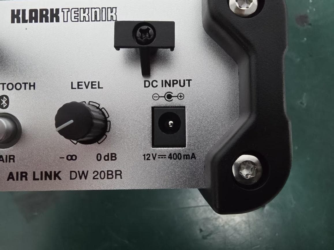
QWHDW20BR1
Mar 29, 2026Wireless DI Boxes
Equipment Class
DSS - Part 15 Spread Spectrum Transmitter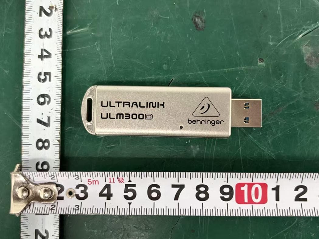
QWHULM300D1
Mar 26, 2026Wireless Microphone System
Equipment Class
DSS - Part 15 Spread Spectrum Transmitter
QWHULM300RD
Mar 26, 2026Wireless Microphone System
Equipment Class
DSS - Part 15 Spread Spectrum Transmitter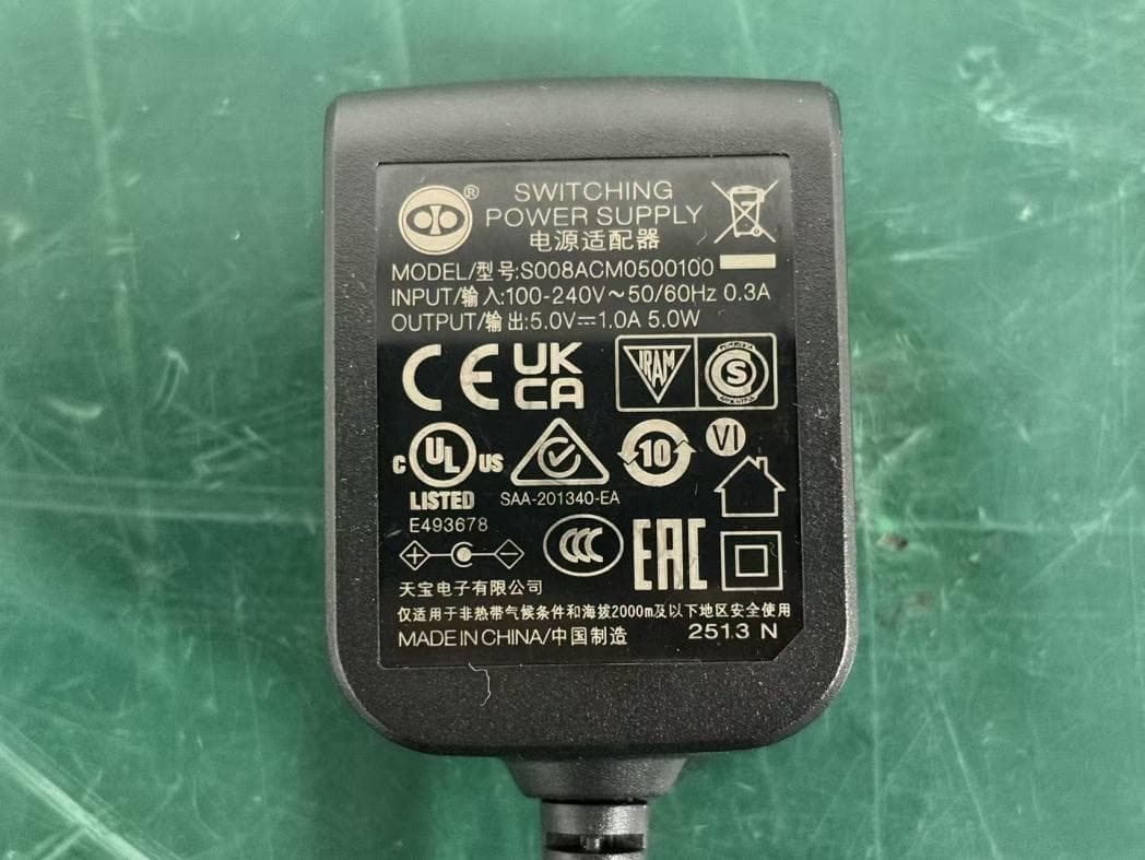
QWHULM300RS
Mar 25, 2026Wireless Microphone System
Equipment Class
DSS - Part 15 Spread Spectrum Transmitter
QWHULM300M1
Mar 24, 2026Wireless Microphones
Equipment Class
DSS - Part 15 Spread Spectrum Transmitter