QWHFLOW8Mixers
Music Tribe Commercial MY Sdn. Bhd.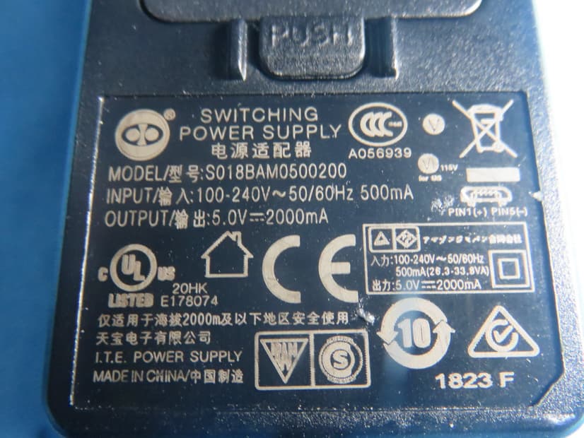
Click to zoom
Application Details
- Equipment Class
- DTS - Digital Transmission System
- Date of Grant
- Feb 24, 2020
- Application Purpose
- Original Equipment
- Date of Application
- Feb 23, 2020
- Equipment Note
- Mixers
- Frequency Range
- 2402.00000000 - 2480.00000000
- Country
- Malaysia
Documents & Files
Document Text
Text extracted from the exhibit documents filed with the FCC. Open a document above to read the original.
Users Manual
Quick Start Guide FLOW 8 8-Input Digital Mixer with Bluetooth Audio and App Control, 60 mm Channel Faders, 2 FX Processors and USB/Audio Interface V 1.0 A54-XXXXX-XXXXX Terminals marked with this symbol carry electrical current of sufficient magnitude to constitute risk of electric shock. Use only high-quality professional speaker cables with ¼" TS or twist-locking plugs pre-installed. All other installation or modification should be performed only by qualified personnel. This symbol, wherever it appears, alerts you to the presence of uninsulated dangerous voltage inside the enclosure - voltage that may be sufficient to constitute a risk of shock. This symbol, wherever it appears, alerts you to important operating and maintenance instructions in the accompanying literature. Please read the manual. Caution To reduce the risk of electric shock, do not remove the top cover (or the rear section). No user serviceable parts inside. Refer servicing to qualified personnel. Caution To reduce the risk of fire or electric shock, do not expose this appliance to rain and moisture. The apparatus shall not be exposed to dripping or splashing liquids and no objects filled with liquids, such as vases, shall be placed on the apparatus. Caution These service instructions are for use by qualified service personnel only. To reduce the risk of electric shock do not perform any servicing other than that contained in the operation instructions. Repairs have to be performed by qualified service personnel. 1. Read these instructions. 2. Keep these instructions. 3. Heed all warnings. 4. Follow all instructions. 5. Do not use this apparatus near water. 6. Clean only with dry cloth. 7. Do not block any ventilation openings. Install in accordance with the manufacturer’s instructions. 8. Do not install near any heat sources such as radiators, heat registers, stoves, or other apparatus (including amplifiers) that produce heat. 9. Do not defeat the safety purpose of the polarized or grounding-type plug. A polarized plug has two blades with one wider than the other. A grounding-type plug has two blades and a third grounding prong. The wide blade or the third prong are provided for your safety. If the provided plug does not fit into your outlet, consult an electrician for replacement of the obsolete outlet. 10. Protect the power cord from being walked on or pinched particularly at plugs, convenience receptacles, and the point where they exit from the apparatus. 11. Use only attachments/accessories specified by the manufacturer. 12 . Use only with the cart, stand, tripod, bracket, or table specified by the manufacturer, or sold with the apparatus. When a cart is used, use caution when moving the cart/ apparatus combination to avoid injury from tip-over. 13. Unplug this apparatus during lightning storms or when unused for long periods of time. 14 . Refer all servicing to qualified service personnel. Servicing is required when the apparatus has been damaged in any way, such as power supply cord or plug is damaged, liquid has been spilled or objects have fallen into the apparatus, the apparatus has been exposed to rain or moisture, does not operate normally, or has been dropped. 15. The apparatus shall be connected to a MAINS socket outlet with a protective earthing connection. 16. Where the MAINS plug or an appliance coupler is used as the disconnect device, the disconnect device shall remain readily operable. 17. Correct disposal of this product: This symbol indicates that this product must not be disposed of with household waste, according to the WEEE Directive (2012/19/EU) and your national law. This product should be taken to a collection center licensed for the recycling of waste electrical and electronic equipment (EEE). The mishandling of this type of waste could have a possible negative impact on the environment and human health due to potentially hazardous substances that are generally associated with EEE. At the same time, your cooperation in the correct disposal of this product will contribute to the efficient use of natural resources. For more information about where you can take your waste equipment for recycling, please contact your local city office, or your household waste collection service. 18. Do not install in a confined space, such as a book case or similar unit. 19. Do not place naked flame sources, such as lighted candles, on the apparatus. 20. Please keep the environmental aspects of battery disposal in mind. Batteries must be disposed-of at a battery collection point. 21. Use this apparatus in tropical and/or moderate climates. Music Tribe accepts no liability for any loss which may be suffered by any person who relies either wholly or in part upon any description, photograph, or statement contained herein. Technical specifications, appearances and other information are subject to change without notice. LEGAL DISCLAIMER Important Safety Instructions 3Quick Start Guide2FLOW 8 All trademarks are the property of their respective owners. Midas, Klark Teknik, Lab Gruppen, Lake, Tannoy, Turbosound, TC Electronic, TC Helicon, Behringer, Bugera, Auratone and Coolaudio are trademarks or registered trademarks of Music Tribe Global Brands Ltd. © Music Tribe Global Brands Ltd. 2020 All rights reserved. For the applicable warranty terms and conditions and additional information regarding Music Tribe’s Limited Warranty, please see complete details online at musictribe.com/warranty. Las terminales marcadas con este símbolo transportan corriente eléctrica de magnitud suficiente como para constituir un riesgo de descarga eléctrica. Utilice solo cables de altavoz profesionales y de alta calidad con conectores TS de 6,3 mm o de bayoneta prefijados. Cualquier otra instalación o modificación debe ser realizada únicamente por un técnico cualificado. Este símbolo, siempre que aparece, le advierte de la presencia de voltaje peligroso sin aislar dentro de la caja; este voltaje puede ser suficiente para constituir un riesgo d…
Text truncated - open the document above for the full version.
External Photos
Project No.: 1909C163 Page 2 of 16 Project No.: 1909C163 Page 3 of 16 Project No.: 1909C163 Page 4 of 16 Adapter: S018BAM0500200 Project No.: 1909C163 Page 5 of 16 Project No.: 1909C163 Page 6 of 16 Project No.: 1909C163 Page 7 of 16 Adapter: GPE018A-050200-Z Project No.: 1909C163 Page 8 of 16
ID Label/Location Info
label location
Internal Photos
Project No.: 1909C163 Page 9 of 16 Project No.: 1909C163 Page 10 of 16 Project No.: 1909C163 Page 11 of 16 Project No.: 1909C163 Page 12 of 16 Project No.: 1909C163 Page 13 of 16 Project No.: 1909C163 Page 14 of 16 Project No.: 1909C163 Page 15 of 16 Project No.: 1909C163 Page 16 of 16 Ant.
RF Exposure Info
Report No.: BTL-FCCP-3-1909C163 Page 1 of 7 FCC RF EXPOSURE REPORT FCC ID: QWHFLOW8 Project No. : 1909C163 Equipment : Mixers Brand Name : BEHRINGER Test Model : FLOW 8 Series Model : NA Applicant : MUSIC Tribe Manufacturing PH Ltd. Address : 17A Brunswick Street Hamilton HM 10 Bermuda Manufacturer : MUSIC Tribe Manufacturing PH Ltd. Address : 17A Brunswick Street Hamilton HM 10 Bermuda Factory : Zhongshan Eurotec Electronics Ltd. Address : No.10 Wanmei Road, South China Modern Chinese Medicine Park, Nanlang Town, Zhongshan City, Guangdong Province, P.R. China Date of Receipt : Sep. 26, 2019 Date of Test : Sep. 27, 2019 ~ Jan. 16, 2020 Issued Date : Feb. 12, 2020 Report Version : R00 Test Sample : Engineering Sample No.: DG201911152 Standard(s) : FCC Guidelines for Human Exposure IEEE C95.1 & KDB447498 D01 The above equipment has been tested and found compliance with the requirement of the relative standards by BTL Inc. Prepared by : Vincent Tan Approved by : Ethan Ma Add: No.3, Jinshagang 1st Road, Shixia, Dalang Town,Dongguan, Guangdong, China. Tel: +86-769-8318-3000 Web: www.newbtl.com Report No.: BTL-FCCP-3-1909C163 Page 2 of 7 REPORT ISSUED HISTORY Report Version Description Issued Date R00 Original Issue. Feb. 12, 2020 Report No.: BTL-FCCP-3-1909C163 Page 3 of 7 1. GENERAL INFORMATION 1.1 GENERAL DESCRIPTION OF EUT Equipment Mixers Brand Name BEHRINGER Te s t Model FLOW 8 Series Model N/A Model Difference(s) N/A Hardware Version P0DNM-V1 Software Version P0DNM-V1 Power Source DC Voltage supplied from AC/DC adapter. 1# Model: S018BAM0500200 2# Model: GPE018A-050200-Z Power Rating 1# I/P: 100-240V ~ 50/60Hz 500mA O/P: 5.0V −−− 2000mA 2# I/P: 100-240V ~ 50/60Hz 0.5A O/P: 5.0V −−− 2000mA Product Description for BT Operation Frequency 2402 MHz ~ 2480 MHz Modulation Technology GFSK, π/4-DQPSK Bit Rate of Transmitter 1Mbps, 2Mbps Max. Output Power 1Mbps: 8.69 dBm 2Mbps: 8.67 dBm Product Description for LE Operation Frequency 2402 MHz ~ 2480 MHz Modulation Technology GFSK Bit Rate of Transmitter 1Mbps Max. Output Power 8.60 dBm Note: 1. For a more detailed features description, please refer to the manufacturer’s specifications or the user's manual. Report No.: BTL-FCCP-3-1909C163 Page 4 of 7 2. Channel List: F o r B T: Channel Frequency (MHz) Channel Frequency (MHz) Channel Frequency (MHz) 00 2402 27 2429 54 2456 01 2403 28 2430 55 2457 02 2404 29 2431 56 2458 03 2405 30 2432 57 2459 04 2406 31 2433 58 2460 05 2407 32 2434 59 2461 06 2408 33 2435 60 2462 07 2409 34 2436 61 2463 08 2410 35 2437 62 2464 09 2411 36 2438 63 2465 10 2412 37 2439 64 2466 11 2413 38 2440 65 2467 12 2414 39 2441 66 2468 13 2415 40 2442 67 2469 14 2416 41 2443 68 2470 15 2417 42 2444 69 2471 16 2418 43 2445 70 2472 17 2419 44 2446 71 2473 18 2420 45 2447 72 2474 19 2421 46 2448 73 2475 20 2422 47 2449 74 2476 21 2423 48 2450 75 2477 22 2424 49 2451 76 2478 23 2425 50 2452 77 2479 24 2426 51 2453 78 2480 25 2427 52 2454 26 2428 53 2455 For LE: Channel Frequency (MHz) Channel Frequency (MHz) 00 2402 20 2442 01 2404 21 2444 02 2406 22 2446 03 2408 23 2448 04 2410 24 2450 05 2412 25 2452 06 2414 26 2454 07 2416 27 2456 08 2418 28 2458 09 2420 29 2460 10 2422 30 2462 11 2424 31 2464 12 2426 32 2466 13 2428 33 2468 14 2430 34 2470 15 2432 35 2472 16 2434 36 2474 17 2436 37 2476 18 2438 38 2478 19 2440 39 2480 Report No.: BTL-FCCP-3-1909C163 Page 5 of 7 3. Table for Filed Antenna: F o r B T: Ant. Brand Model Name Antenna Type Connector Gain (dBi) 1 N/A N/A Internal N/A 1.84 For BLE: Ant. Brand Model Name Antenna Type Connector Gain (dBi) 1 N/A N/A Internal N/A 1.84 Report No.: BTL-FCCP-3-1909C163 Page 6 of 7 2. GENERAL CONCULUSION According to FCC KDB447498 D01, Appendix A, SAR Test Exclusion Thresholds for 100 MHz – 6 GHz and ≤ 50 mm, the 1-g and 10-g SAR test exclusion thresholds are determined by the following: [(max. power of channel, including tune-up tolerance, mW) / (min. test separation distance, mm)] · [√f(GHz)] ≤ 3.0 for 1-g SAR, and ≤ 7.5 for 10-g extremity SAR, where f(GHz) is the RF channel transmit frequency in GHz Power and distance are rounded to the nearest mW and mm before calculation The result is rounded to one decimal place for comparison Appendix A - SAR Test Exclusion Thresholds for 100 MHz - 6 GHz and < 50 mm MHz 5 10 15 20 25 30 35 40 45 50 mm 150 39 77 116 155 194 232 271 310 349 387 SAR Test Exclusion Thresholds (mW) 300 27 55 82 110 137 164 192 219 246 274 450 22 45 67 89 112 134 157 179 201 224 835 16 33 49 66 82 98 115 131 148 164 900 16 32 47 63 79 95 111 126 142 158 1500 12 24 37 49 61 73 86 98 110 122 1900 11 22 33 44 54 65 76 87 98 109 2450 10 19 29 38 48 57 67 77 86 96 3600 8 16 24 32 40 47 55 63 71 79 5200 7 13 20 26 33 39 46 53 59 66 5400 6 13 19 26 32 39 45 52 58 65 5800 6 12 19 25 31 37 44 50 56 62 Report No.: BTL-FCCP-3-1909C163 Page 7 of 7 3. TEST RESULTS Tune up tolerance (dBm) BT 1.0 Tune up tolerance (dBm) LE 1.0 Max. Output Power (dBm) Max. Output Power (mW) Limit (mW) 9.69 9.3111 10 Note: (1) Output power including tune up tolerance. (2) The maximum measured output peak power of this EUT is 9.3111mW, less than 10mW at 5mm distance. Conclusion: No SAR evaluation required since transmitter power is below FCC threshold. End of Test Report Project No.: 1909C163 Page 1 of 16 ATTACHMENT PHOTOGRAPHS OF EUT Project No.: 1909C163 Page 2 of 16 Project No.: 1909C163 Page 3 of 16 Project No.: 1909C163 Page 4 of 16 Adapter: S018BAM0500200 Project No.: 1909C163 Page 5 of 16 Project No.: 1909C163 Page 6 of 16 Project No.: 1909C163 Page 7 of 16 Adapter: GPE018A-050200-Z Project No.: 1909C163 Page 8 of 16 Project No.: 1909C163 Page 9 of 16 Project No.: 1909C163 Page 10 of 16 Project No.: 1909C163 Page 11 of 16 Project No.: 1909C163 Page 12 of 16 Project No.: 1909C163 Page 13 of 16 Project No.: 1909C163 Page 14 of 16 Project No.: 1909C163 Page 15 of 16 Project No.: 1909C163 Page 16 of 16 Ant.
Test Report
Report No.: BTL-FCCP-2-1909C163 Page 1 of 60 FCC Radio Test Report FCC ID: QWHFLOW8 This report concerns: Original Grant Project No. : 1909C163 Equipment : Mixers Brand Name : BEHRINGER Test Model : FLOW 8 Series Model : NA Applicant : MUSIC Tribe Manufacturing PH Ltd. Address : 17A Brunswick Street Hamilton HM 10 Bermuda Manufacturer : MUSIC Tribe Manufacturing PH Ltd. Address : 17A Brunswick Street Hamilton HM 10 Bermuda Factory : Zhongshan Eurotec Electronics Ltd. Address : No.10 Wanmei Road, South China Modern Chinese Medicine Park, Nanlang Town, Zhongshan City, Guangdong Province, P.R. China Date of Receipt : Sep. 26, 2019 Date of Test : Sep. 27, 2019 ~ Jan. 16, 2020 Issued Date : Feb. 12, 2020 Report Version : R00 Test Sample : Engineering Sample No.: DG201911152 Standard(s) : FCC Part15, Subpart C (15.247) ANSI C63.10-2013 FCC KDB 558074 D01 15.247 Meas Guidance v05r02 The above equipment has been tested and found compliance with the requirement of the relative standards by BTL Inc. Prepared by : Vincent Tan Approved by : Ethan Ma Add: No.3, Jinshagang 1st Road, Shixia, Dalang Town,Dongguan, Guangdong, China. Tel: +86-769-8318-3000 Web: www.newbtl.com Report No.: BTL-FCCP-2-1909C163 Page 2 of 60 Declaration BTL represents to the client that testing is done in accordance with standard procedures as applicable and that test instruments used has been calibrated with standards traceable to international standard(s) and/or national standard(s). BTL's reports apply only to the specific samples tested under conditions. It is manufacture’s responsibility to ensure that additional production units of this model are manufactured with the identical electrical and mechanical components. BTL shall have no liability for any declarations, inferences or generalizations drawn by the client or others from BTL issued reports. The report must not be used by the client to claim product certification, approval, or endorsement by NVLAP, NIST, A2LA, or any agency of the U.S. Government. This report is the confidential property of the client. As a mutual protection to the clients, the public and ourselves, the test report shall not be reproduced, except in full, without our written approval. BTL’s laboratory quality assurance procedures are in compliance with the ISO/IEC 17025 requirements, and accredited by the conformity assessment authorities listed in this test report. BTL is not responsible for the sampling stage, so the results only apply to the sample as received. The information, data and test plan are provided by manufacturer which may affect the validity of results, so it is manufacturer’s responsibility to ensure that the apparatus meets the essential requirements of applied standards and in all the possible configurations as representative of its intended use. Limitation For the use of the authority's logo is limited unless the Test Standard(s)/Scope(s)/Item(s) mentioned in this test report is (are) included in the conformity assessment authorities acceptance respective. Please note that the measurement uncertainty is provided for informational purpose only and are not use in determining the Pass/Fail results. Report No.: BTL-FCCP-2-1909C163 Page 3 of 60 Table of Contents Page REPORT ISSUED HISTORY 5 1 . SUMMARY OF TEST RESULTS 6 1.1 TEST FACILITY 7 1.2 MEASUREMENT UNCERTAINTY 7 1.3 TEST ENVIRONMENT CONDITIONS 7 2 . GENERAL INFORMATION 8 2.1 GENERAL DESCRIPTION OF EUT 8 2.2 DESCRIPTION OF TEST MODES 10 2.3 PARAMETERS OF TEST SOFTWARE 10 2.4 BLOCK DIAGRAM SHOWING THE CONFIGURATION OF SYSTEM TESTED 11 2.5 SUPPORT UNITS 11 3 . AC POWER LINE CONDUCTED EMISSIONS TEST 12 3.1 LIMIT 12 3.2 TEST PROCEDURE 12 3.3 DEVIATION FROM TEST STANDARD 12 3.4 TEST SETUP 13 3.5 EUT OPERATING CONDITIONS 13 3.6 TEST RESULTS 13 4 . RADIATED EMISSION TEST 14 4.1 LIMIT 14 4.2 TEST PROCEDURE 15 4.3 DEVIATION FROM TEST STANDARD 15 4.4 TEST SETUP 16 4.5 EUT OPERATING CONDITIONS 18 4.6 TEST RESULT - 9 KHZ TO 30 MHZ 18 4.7 TEST RESULT - 30 MHZ TO 1000 MHZ 18 4.8 TEST RESULT - ABOVE 1000 MHZ 18 5 . BANDWIDTH TEST 19 5.1 LIMIT 19 5.2 TEST PROCEDURE 19 5.3 DEVIATION FROM STANDARD 19 5.4 TEST SETUP 19 5.5 EUT OPERATION CONDITIONS 19 Report No.: BTL-FCCP-2-1909C163 Page 4 of 60 Table of Contents Page 5.6 TEST RESULTS 19 6 . MAXIMUM OUTPUT POWER 20 6.1 LIMIT 20 6.2 TEST PROCEDURE 20 6.3 DEVIATION FROM STANDARD 20 6.4 TEST SETUP 20 6.5 EUT OPERATION CONDITIONS 20 6.6 TEST RESULTS 20 7 . CONDUCTED SPURIOUS EMISSION 21 7.1 LIMIT 21 7.2 TEST PROCEDURE 21 7.3 DEVIATION FROM STANDARD 21 7.4 TEST SETUP 21 7.5 EUT OPERATION CONDITIONS 21 7.6 TEST RESULTS 21 8 . POWER SPECTRAL DENSITY TEST 22 8.1 LIMIT 22 8.2 TEST PROCEDURE 22 8.3 DEVIATION FROM STANDARD 22 8.4 TEST SETUP 22 8.5 EUT OPERATION CONDITIONS 22 8.6 TEST RESULTS 22 9 . MEASUREMENT INSTRUMENTS LIST 23 10 . EUT TEST PHOTO 25 APPENDIX A - AC POWER LINE CONDUCTED EMISSIONS 29 APPENDIX B - RADIATED EMISSION - 9 KHZ TO 30 MHZ 32 APPENDIX C - RADIATED EMISSION - 30 MHZ TO 1000 MHZ 37 APPENDIX D - RADIATED EMISSION - ABOVE 1000 MHZ 40 APPENDIX E - BANDWIDTH 53 APPENDIX F - MAXIMUM OUTPUT POWER 55 APPENDIX G - CONDUCTED SPURIOUS EMISSION 57 APPENDIX H - POWER SPECTRAL DENSITY 59 Report No.: BTL-FCCP-2-1909C163 Page 5 of 60 REPORT ISSUED HISTORY Report Version Description Issued Date R00 Original Issue. Feb. 12, 2020 Report No.: BTL-FCCP-2-1909C163 Page 6 of 60 1. SUMMARY OF TEST RESULTS Test procedures according to the technical standard(s): FCC Part15, Subpart C (15.247) Standard(s) Section Test Item Test Result Judgment Remark 15.207 AC Power Line Conducted Emissions APPENDIX A PASS ------ 15.247(d) 15.205(a) 15.209(a) Radiated Emissions APPENDIX B APPENDIX C APPENDIX D PASS ------ 15.247(a)(2) Bandwidth APPENDIX E PASS ------ 15.247(b)(3) Maximum Output Power APPENDIX F PASS ------ 15.247(d) Conducted Spurious Emission APPENDIX G PASS ------ 15.247(e) Power Spectral Density APPENDIX H PASS ------ 15.203 Antenna Requirement ------ PASS Note 2 Note: (1) “N/A” denotes test is not applica…
Text truncated - open the document above for the full version.
Test Report
Project No.: 1909C163 Page 15 of 16 Project No.: 1909C163 Page 16 of 16 Ant.
Test Setup Photos
Report No.: BTL-FCCP-1-1909C163 Page 30 of 89 12.EUT TEST PHOTO A C Power Line Conducted Emissions Test Photos Report No.: BTL-FCCP-1-1909C163 Page 31 of 89 Radiated Emissions Test Photos 9 kHz to 30 MHz Report No.: BTL-FCCP-1-1909C163 Page 32 of 89 Radiated Emissions Test Photos 30 MHz to 1000 MHz Report No.: BTL-FCCP-1-1909C163 Page 33 of 89 Radiated Emissions Test Photos Above 1 GHz
Contact Information
Applicant
Kane Xin(Innovation Compliance Leader)
Technical Contact
Non-Technical Contact
BTL Inc.Mandy Wang
[email protected]86-769-83183000
Test Firm
BTL Inc.Sophia Huang
[email protected]+86-769-83183000
Technical Specifications
| # | Rule Parts | Frequency Range | Power Output |
|---|---|---|---|
| 1 | 15C | 2.40 GHz - 2.48 GHz | 7.20 mW |
Other Applications from Music Tribe Commercial MY Sdn. Bhd.
QWHDW20BR1
Mar 29, 2026Wireless DI Boxes
Equipment Class
DSS - Part 15 Spread Spectrum Transmitter
QWHULM300D1
Mar 26, 2026Wireless Microphone System
Equipment Class
DSS - Part 15 Spread Spectrum Transmitter
QWHULM300RD
Mar 26, 2026Wireless Microphone System
Equipment Class
DSS - Part 15 Spread Spectrum Transmitter
QWHULM300RS
Mar 25, 2026Wireless Microphone System
Equipment Class
DSS - Part 15 Spread Spectrum Transmitter
QWHULM300M1
Mar 24, 2026Wireless Microphones
Equipment Class
DSS - Part 15 Spread Spectrum Transmitter