QWHGOCAMWireless Microphones
Music Tribe Commercial MY Sdn. Bhd.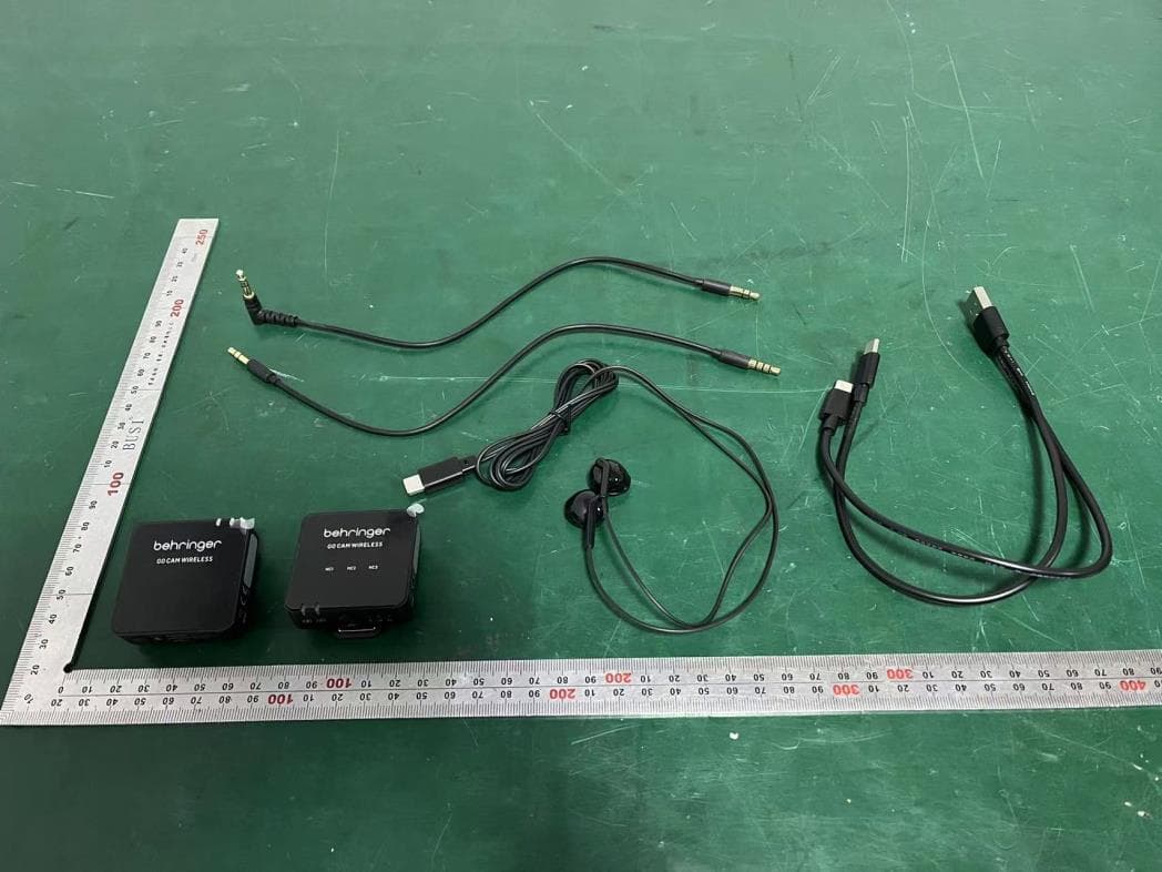
Click to zoom
Application Details
- Equipment Class
- DSS - Part 15 Spread Spectrum Transmitter
- Date of Grant
- Mar 18, 2024
- Application Purpose
- Original Equipment
- Date of Application
- Mar 18, 2024
- Equipment Note
- Wireless Microphones
- Frequency Range
- 2402.00000000 - 2480.00000000
- Country
- Malaysia
Documents & Files
Document Text
Text extracted from the exhibit documents filed with the FCC. Open a document above to read the original.
Users Manual
Page 1 V 1.0 (EN) Safety Instruction 1. Read these instructions. 2. Keep these instructions. 3. Heed all warnings. 4. Follow all instructions. 5. Do not use this apparatus near water. 6. Clean only with dry cloth. 7. Do not block any ventilation openings. Install in accordance with the manufacturer’s instructions. 8. Do not install near any heat sources such as radiators, heat registers, stoves, or other apparatus (including amplifiers) that produce heat. 9. Use only attachments/accessories specified by the manufacturer. 10. Use only with the cart, stand, tripod, bracket, or table specified by the manufacturer, or sold with the apparatus. When a cart is used, use caution when moving the cart/apparatus combination to avoid injury from tip-over. 11. Correct disposal of this product: This symbol indicates that this product must not be disposed of with household waste, according to the WEEE Directive (2012/19/EU) and your national law. This product should be taken to a collection center licensed for the recycling of waste electrical and electronic equipment (EEE). The mishandling of this type of waste could have a possible negative impact on the environment and human health due to potentially hazardous substances that are generally associated with EEE. At the same time, your cooperation in the correct disposal of this product will contribute to the efficient use of natural resources. For more information about where you can take your waste equipment for recycling, please contact your local city office, or your household waste collection service. 12. Do not install in a confined space, such as a book case or similar unit. 13. Do not place naked flame sources, such as lighted candles, on the apparatus. 14. Operating temperature range 5° to 45° C (41° to 113° F). 15. WARNING Replacement of a battery with an incorrect type can defeat a safeguard. Disposal of a battery into fire or a hot oven, or mechanically crushing or cutting of a battery can result in an explosion. Leaving a battery in an extremely high temperature surrounding environment can result in an explosion or the leakage of flammable liquid or gas. A battery subjected to extremely low air pressure may result in an explosion or the leakage of flammable liquid or gas. Attention should be drawn to the environmental aspects of battery disposal. Batteries (battery pack or batteries installed) shall not be exposed to excessive heat such as sunshine, fire or the like. GO CAM WIRELESS Digital Wireless Clip-On Microphone System for Content Creators (1) External microphone input, 3.5 mm (1/8") (2) Built-in microphone (3) Wireless status LED - blue LED = successful connection to receiver, flashing blue = not connected (4) Battery status LED - red LED = charging, flashing red = low battery (5) Shirt clip (6) Power On/Off - press for 2 seconds to turn ON, press for 3 seconds to turn OFF (7) USB Type C charging port (8) Mute On/Off - double-click = ON, press once = OFF GO CAM WIRELESS • Get professional-grade audio with our wireless microphone system, designed to work seamlessly with your video recorders, DSLRs, mobile devices, tablets, and audio recorders • Perfect for interviews, podcasts, live-streaming, vlogs, virtual classrooms, voice overs, and video production • Experience superior performance with Go Cam Wireless’s 30 m (100 ft) wireless freedom • Keep your hands free with our compact transmitter, featuring a convenient shirt clip and easy on/off switch • Capture clear audio with ease using our integrated omnidirectional microphone • Eliminate unwanted background noise with our receiver’s state-of-the-art 3-level noise reduction switch • Easily adjust the gain with our user-friendly 3-level switch that offers -24dB, -12dB, and 0dB options • Mount our specially designed receiver on your camera using the built-in camera shoe adapter • Enjoy real-time monitoring with our included earphones • Connect an external microphone with transmitter using 3.5 mm (1/8”) connector • Stay powered up and protected on the go with up to 8 hours of runtime and our camera connection cable, USB charging cables, fur windscreen, and protective carry case Accessories Supplied • Fur windshield x 1 • USB charging cable x 1 • TRS to TRS audio cable for Camera x 1 • TRRS to TRS audio cable for Phones x 1 • Type C to Type C audio cable for Phones x 1 • Type C earphones x 1 (9) Gain LEDs - III = 0 dB, II = -12 dB, I = -24 dB (10) Gain switch - press once to select a different gain level (11) Wireless status LED - blue LED = successful connection to receiver, flashing blue = not connected (12) Battery status LED - red LED = charging, flashing red = low battery (13) Noise reduction LEDs - mild = NC1, medium = NC2, strong = NC3 (14) Audio output, 3.5 mm (1/8") (15) Power On/Off - press for 2 seconds to turn ON, press for 3 seconds to turn OFF (16) USB Type C charging port and earphones output for real-time monitoring (17) Noise reduction switch - press once to select a different level (18) Clip/camera shoe adaptor MICROPHONE CONTROLSRECEIVER CONTROLS (6) (2)(1) (3)(4) (5) (7)(8) (11) (18) (15)(16) (17) (14) (13) (9)(10) (12) Operation A charger is not included. The power delivered by the charger must be between 5V/32mA (0.16W) minimum required by this equipment, and 5V/400mA (2W) maximum, in order to achieve the maximum charging speed. This equipment supports the USB Power Delivery charging protocol. 1. Please charge the transmitter and receiver before use. 2. Press the receiver power switch and the transmitter power switch for 2 seconds to power ON. Receiver Transmitter 3. A solid Blue LED indicates that the wireless connection between receiver and transmitter is successful. 4. Clip the transmitter to your shirt, t-shirt, or jacket. 5. Please make sure the built-in microphone is not covered or blocked. For optimum audio recording performance, we recommended the distance between the user’s mouth and the transmitter's microphone is 15 to 20 cm. 6. If the audio is too loud, c…
Text truncated - open the document above for the full version.
Attestation Statements
Music Tribe Commercial MY Sdn. Bhd. Covered Equipment Certification Attestation Letter 2/19/2024 Federal Communications Commission Authorization and Evaluation Division 7435 Oakland Mills Road Columbia, MD 21046 USA ATTN.: Reviewing Engineer FCC ID: QWHGOCAM Music Tribe Commercial MY Sdn. Bhd. (“the applicant”) certifies that the equipment for which authorization is sought is not “covered” equipment prohibited from receiving an equipment authorization pursuant to section 2.903 of the FCC rules. Note: If the equipment for which the applicant seeks authorization is produced by any of the entities identified on the current Covered List, the applicant should include an explanation on why the equipment is not “covered” equipment. Signed: Printed name: Kane Xin Title: Innovation Compliance Leader Company Name: Music Tribe Commercial MY Sdn. Bhd. Date: 2/19/2024
Attestation Statements
Music Tribe Commercial MY Sdn. Bhd. * the applicant must designate a contact located in the United States for purposes of acting as the applicant’s agent for service of process, regardless of whether the applicant is a domestic or foreign entity. An applicant located in the United States may designate itself as the agent for service of process. U.S. Agent Designation for Service of Process - Certification Attestation Letter 2/19/2024 Federal Communications Commission Authorization and Evaluation Division 7435 Oakland Mills Road Columbia, MD 21046 USA ATTN.: Reviewing Engineer FCC ID: QWHGOCAM FRN of applicant: 0022048235 Per section 2.911(d)(7) of the FCC rules, Music Tribe Commercial MY Sdn. Bhd. (“the applicant”) certifies that the equipment for which authorization is sought is designated to the following U.S. agent* for service of process: Company Name: Music Tribe Commercial NV Inc. FCC Registration Number (FRN): 0033426594 Physical U.S. Company Address: 122 E. 42nd St.1, 8th Floor NY, NY 10168, United States Contact Person: Chase McKnight Agent Email Address: [email protected] The above contact person accepts the obligation for service of process. The applicant accepts to maintain an agent for no less than one year after the grantee has terminated all marketing and importation or the conclusion of any Commission-related proceeding involving the equipment. Applicant Signed: Agent Signed (if different from Applicant): Signed: Signed: Printed name: Kane Xin Printed name: Chase McKnight Title: Innovation Compliance Leader Title: President Company Name: Music Tribe Commercial MY Sdn. Bhd. Company Name: Music Tribe Commercial NV Inc. Date: 2/19/2024 Date: 2/19/2024
Attestation Statements
Music Tribe Commercial MY Sdn. Bhd. Covered Equipment Certification Attestation Letter 2/19/2024 Federal Communications Commission Authorization and Evaluation Division 7435 Oakland Mills Road Columbia, MD 21046 USA ATTN.: Reviewing Engineer FCC ID: QWHGOCAM Music Tribe Commercial MY Sdn. Bhd. (“the applicant”) certifies that, as of the date of the filing of the application, the applicant is not identified on the Covered List as an entity producing “covered” equipment. Signed: Printed name: Kane Xin Title: Innovation Compliance Leader Company Name: Music Tribe Commercial MY Sdn. Bhd. Date: 2/19/2024
Cover Letter(s)
DATE : 3/4/2024 Federal Communications Commission Authorization & Evaluation Division 7345 Oakland Mills Road Columbia, Maryland 21046 Authority to Act as Agent On our behalf, I appoint EST Technology Co., Ltd. Address:Chilingxiang, Qishantou, Santun, Houjie, Dongguan, Guangdong, China to act as our agent in the preparation of this application for equipment certification. I certify that submitted documents properly describe the device or system for which equipment certification is sought. I also certify that each unit manufactured, imported or marketed, as defined in the Federal Communications Commission’s regulations will have affixed to it a label identical to that submitted for approval with this application. For instances where our authorized agent signs the application for certification on our behalf, I acknowledge that all responsibility for complying with the terms and conditions for certification, still resides with Music Tribe Commercial MY Sdn. Bhd. Address: 1-17- 02, Suntech @ Penang Cybercity, LinTang Mayang Pasir 3, Bayan Baru, Pulau Pinang, Malaysia <Signature> Name:Kane Xin Title:Innovation Compliance Leader Applicant Company:Music Tribe Commercial MY Sdn. Bhd.
Cover Letter(s)
DATE : 3/4/2024 Equipment Autorisation Division Federal Communications Commission 7435 Oakland Mills Road Columbia, MD 21046 FCC ID: QWHGOCAM Product Name: Wireless Microphones Request for Confidentiality Pursuant to Sections 0.457 and 0.459 of the commissions rules, we hereby request that the following documents be held confidential: • Schematics • Block diagram • Operation description These materials contain trade secrets and proprietary information and are not customarily released to the public. The public disclosure of this information might be harmful to the company and provide unjustified benefits to our competitors. <Signature> Name:Kane Xin Title:Innovation Compliance Leader Company:Music Tribe Commercial MY Sdn. Bhd.
Cover Letter(s)
Music Tribe Commercial MY Sdn. Bhd. Family Certification Attestation Letter 3/18/2024 Equipment Autorisation Division Federal Communications Commission 7435 Oakland Mills Road Columbia, MD 21046 ATTN.: Reviewing Engineer FCC ID: QWHGOCAM Models: GO CAM WIRELESS, GO CAM WIRELESS 2 We hereby request Family Certification for the above mentioned Models based on them being identical in enclosure/form factor, internal circuitry/PCB components, hardware and the only difference is in the marketing model names, accessory and ADK software as described in the table below. Model Item Difference 1 GO CAM WIRELESS (Fully Tested Model) Package has: DUT x1pc, receiver x1pc GO CAM WIRELESS 2 Package has: DUT x2pcs, receiver x1pc Therefore, testing on model GO CAM WIRELESS is demonstrative of compliance of all Models subject of this application. Signed: Printed name: Kane Xin Title: Innovation Compliance Leader Date: 3/18/2024
External Photos
External Photos M/N: GO CAM WIRELESS External Photos M/N: GO CAM WIRELESS External Photos M/N: GO CAM WIRELESS External Photos M/N: GO CAM WIRELESS
Internal Photos
Internal Photos M/N: GO CAM WIRELESS Internal Photos M/N: GO CAM WIRELESS Internal Photos M/N: GO CAM WIRELESS PCB Antenna Internal Photos M/N: GO CAM WIRELESS
RF Exposure Info
Page 1 of 3 Report No. ESTE-R2401510 FCC RF EXPOSURE REPORT Music Tribe Commercial MY Sdn. Bhd. Wireless Microphones Model Number: GO CAM WIRELESS Addition Model: GO CAM WIRELESS 2 FCC ID: QWHGOCAM Applicant: Music Tribe Commercial MY Sdn. Bhd. Address: 1-17-02, Suntech @ Penang Cybercity, LinTang Mayang Pasir 3, Bayan Baru, Pulau Pinang, Malaysia Prepared By: EST Technology Co., Ltd. Chilingxiang, Qishantou, Santun, Houjie, Dongguan, Guangdong, China Tel: 86-769-83081888-808 Report Number: ESTE-R2401510 Date of Test: Dec. 13, 2023 ~ Jan. 29, 2024 Date of Report: Feb. 05, 2024 Page 2 of 3 Report No. ESTE-R2401510 1. Applicable Standards FCC Part 2(Section 2.1093) FCC KDB 447498 D04 Interim General RF Exposure Guidance v01 2. Exposure Evaluation of Portable or Mobile Devices Human exposure to RF emissions from portable devices (47 CFR §2.1093), as defined by the FCC, must be evaluated with respect to the FCC-adopted limits for SAR. Evaluation of mobile devices, as defined by the FCC, may also be performed with respect to SAR limits, but in such cases it is usually simpler and more cost-effective to evaluate compliance with respect to field strength or power density limits. For certain devices that are designed to be used in both mobile and portable configurations similar to those described in 47 CFR §2.1091(d)(4), such as certain desktop phones and wireless modem modules, compliance for mobile configurations is also satisfied when the same device is evaluated for SAR compliance in portable configurations. The test exclusions are applicable only when the minimum test separation distance is ≤ 50 mm and for transmission frequencies between 300 MHz and 6 GHz. When the minimum test separation distance is < 5 mm, a distance of 5 mm is applied to determine SAR test exclusion. Page 3 of 3 Report No. ESTE-R2401510 3. Evaluation Results Mode Frequency (MHz) Peak output Power (dBm) Antenna Gain (dBi) effective radiated power (dBm) Target power (dBm) Max. Target power (mW) SAR Test Exemption Limit (mW) GFSK 2402 2.96 -0.15 0.66 2±1 1.995 2.72 2441 3.34 -0.15 1.04 3±1 2.512 2.72 2480 3.74 -0.15 1.44 3±1 2.512 2.72 Note: 1. Limited=3060*(0.5/20)^x, x=-log(60/(3060*√f)). 2. We choose f=2.48GHz (Highest frequency operate at TX) to calculate MPE limit as higher frequency will have lower MPE limits. 3. SAR Test Exclusion Thresholds is 2.72mW for separation distance 5mm. Therefore, SAR test is not required. End of Test Report
Test Report
Page 1 of 75 Report No. ESTE-R2401509 FCC PART 15C TEST REPORT FOR CERTIFICATION On Behalf of Music Tribe Commercial MY Sdn. Bhd. Wireless Microphones Model Number: GO CAM WIRELESS Addition Model: GO CAM WIRELESS 2 FCC ID: QWHGOCAM Applicant : Music Tribe Commercial MY Sdn. Bhd. Address: 1-17-02, Suntech @ Penang Cybercity, LinTang Mayang Pasir 3, Bayan Baru, Pulau Pinang, Malaysia Prepared By: EST Technology Co., Ltd. Chilingxiang, Qishantou, Santun, Houjie, Dongguan, Guangdong, China Tel: 86-769-83081888-808 Report Number: ESTE-R2401509 Date of Test: Dec. 13, 2023 ~ Jan. 29, 2024 Date of Report: Feb. 05, 2024 Page 2 of 75 Report No. ESTE-R2401509 TABLE OF CONTENTS Description Page TEST REPORT VERIFICATION .......................................................................................................... 3 1. GENERAL INFORMATION ................................................................................................................... 5 1.1. Description of Device (EUT) ............................................................................................................ 5 1.2. Antenna Information ......................................................................................................................... 5 1.3. Information of RF Cable ................................................................................................................... 5 2. SUMMARY OF TEST ........................................................................................................................... 6 2.1. Summary of test result ..................................................................................................................... 6 2.2. Test Facilities ..................................................................................................................................... 7 2.3. Measurement uncertainty ................................................................................................................ 8 2.4. Assistant equipment used for test .................................................................................................. 8 2.5. Block Diagram ................................................................................................................................... 8 2.6. Test mode .......................................................................................................................................... 9 2.7. Channel List ..................................................................................................................................... 10 2.8. Power Setting of Test Software .................................................................................................... 10 2.9. Test Equipment ............................................................................................................................... 11 3. MAXIMUM PEAK OUTPUT POWER ................................................................................................... 13 3.1. Limit ................................................................................................................................................... 13 3.2. Test Setup ........................................................................................................................................ 13 3.3. Spectrum Analyzer Setting ............................................................................................................ 13 3.4. Test Procedure ................................................................................................................................ 13 3.5. Test Result ....................................................................................................................................... 13 4. 20 DB BANDWIDTH ......................................................................................................................... 14 4.1. Limit ................................................................................................................................................... 14 4.2. Test Setup ........................................................................................................................................ 14 4.3. Spectrum Analyzer Setting ............................................................................................................ 14 4.4. Test Procedure ................................................................................................................................ 14 4.5. Test Result ....................................................................................................................................... 14 5. CARRIER FREQUENCY SEPARATION .............................................................................................. 15 5.1. Limit ................................................................................................................................................... 15 5.2. Test Setup ........................................................................................................................................ 15 5.3. Spectrum Analyzer Setting ............................................................................................................ 15 5.4. Test Procedure ................................................................................................................................ 15 5.5. Test Result ....................................................................................................................................... 15 6. NUMBER OF HOPPING CHANNEL ................................................................................................... 16 6.1. Limit ................................................................................................................................................... 16 6.2. Test Setup .................................................................................…
Text truncated - open the document above for the full version.
Test Report
1 / 4 Antenna Specification Quick Reference Date Antenna on the system board Frequency Range 2400 ~ 2500MHz Efficiency (dB) -2.51 Efficiency (%) 18.69% Max Gain(dBi) -0.15 Input Impendence (ohm) 50 Polarization Type Vertical & Horizontal V.S.W.R < 2 All the technical data and information contained herein are subject to change without prior notice Antenna Layout on the system board L1 3.0mm L2 1.7mm L3 1.2mm L4 1.6mm L5 2.5mm W1 0.5mm W2 0.3mm 2 / 4 Efficiency & Antenna Gain The Environment of Antenna Radiation Pattern 3 / 4 4 / 4
Test Setup Photos
Conducted Test Radiated Test (30-1000 MHz) Radiated Test (Above 1GHz)
Contact Information
Applicant
Kane Xin(Innovation Compliance Leader)
Test Firm
EST Technology Co., Ltd.Iceman Hu
[email protected]+86 0769-83081888
Technical Specifications
| # | Rule Parts | Frequency Range | Power Output |
|---|---|---|---|
| 1 | 15C | 2.40 GHz - 2.48 GHz | 2.37 mW |
Other Applications from Music Tribe Commercial MY Sdn. Bhd.
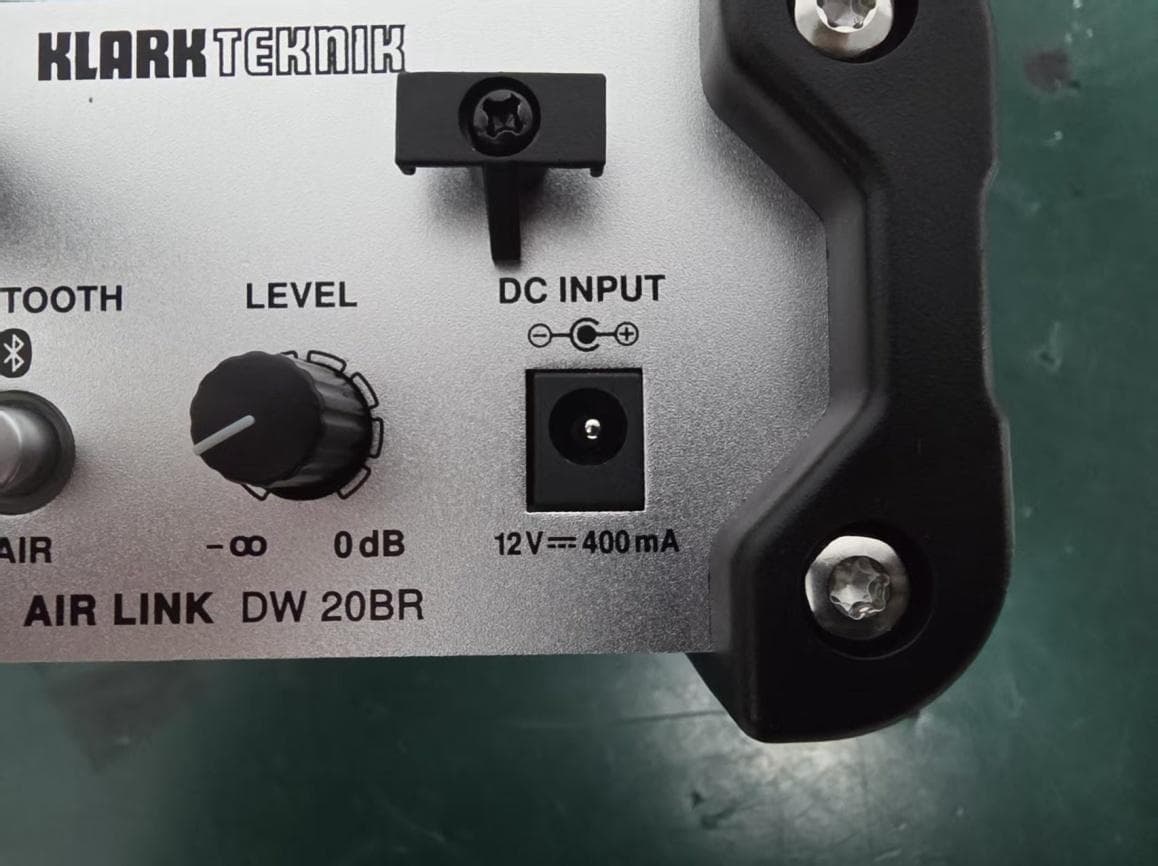
QWHDW20BR1
Mar 29, 2026Wireless DI Boxes
Equipment Class
DSS - Part 15 Spread Spectrum Transmitter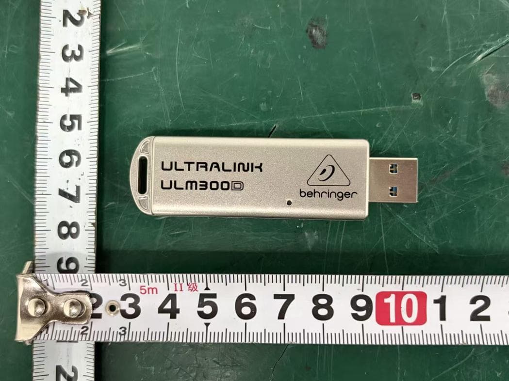
QWHULM300D1
Mar 26, 2026Wireless Microphone System
Equipment Class
DSS - Part 15 Spread Spectrum Transmitter
QWHULM300RD
Mar 26, 2026Wireless Microphone System
Equipment Class
DSS - Part 15 Spread Spectrum Transmitter
QWHULM300RS
Mar 25, 2026Wireless Microphone System
Equipment Class
DSS - Part 15 Spread Spectrum Transmitter
QWHULM300M1
Mar 24, 2026Wireless Microphones
Equipment Class
DSS - Part 15 Spread Spectrum Transmitter