QWHMPA40BTPortable PA System
Music Tribe Commercial MY Sdn. Bhd.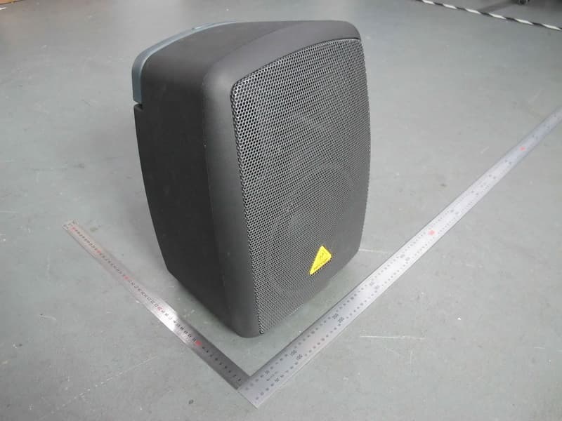
Click to zoom
Application Details
- Equipment Class
- DSS - Part 15 Spread Spectrum Transmitter
- Date of Grant
- May 29, 2013
- Application Purpose
- Original Equipment
- Date of Application
- May 28, 2013
- Equipment Note
- Portable PA System
- Frequency Range
- 2402.00000000 - 2480.00000000
- Country
- Malaysia
Documents & Files
Document Text
Text extracted from the exhibit documents filed with the FCC. Open a document above to read the original.
Users Manual
(Check out behringer.com for Full Manual) Quick Start Guide EUROPORT MPA40BT/MPA40BT- PRO All-in-One Portable PA System with Full Bluetooth Connectivity 2EUROPORT MPA40BT/MPA40BT-PROQuick Start Guide3 Important Safety Instructions LEGAL DISCLAIMER LIMITED WARRANTY Instrucciones de seguridad NEGACIÓN LEGAL GARANTÍA LIMITADA Terminals marked with this symbol carry electrical current of suffi cient magnitude to constitute risk of electric shock. Use only high-quality professional speaker cables with ¼" TS or twist-locking plugs pre-installed. All other installation or modifi cation should be performed only by qualifi ed personnel. This symbol, wherever it appears, alerts you to the presence of uninsulated dangerous voltage inside the enclosure - voltage that may be suffi cient to constitute a risk of shock. This symbol, wherever it appears, alerts you to important operating and maintenance instructions in the accompanying literature. Please read the manual. Caution To reduce the risk of electric shock, do not remove the top cover (or the rear section). No user serviceable parts inside. Refer servicing to qualifi ed personnel. Caution To reduce the risk of fi re or electric shock, do not expose this appliance to rain and moisture. The apparatus shall not be exposed to dripping or splashing liquids and no objects fi lled with liquids, such as vases, shall be placed on the apparatus. Caution These service instructions are for use by qualifi ed service personnel only. To reduce the risk of electric shock do not perform any servicing other than that contained in the operation instructions. Repairs have to be performed by qualifi ed service personnel. 1. Read these instructions. 2. Keep these instructions. 3. Heed all warnings. 4. Follow all instructions. 5. Do not use this apparatus near water. 6. Clean only with dry cloth. 7. Do not block any ventilation openings. Install in accordance with the manufacturer’s instructions. 8. Do not install near any heat sources such as radiators, heat registers, stoves, or other apparatus (including amplifi ers) that produce heat. 9. Do not defeat the safety purpose of the polarized or grounding-type plug. A polarized plug has two blades with one wider than the other. A grounding-type plug has two blades and a third grounding prong. The wide blade or the third prong are provided for your safety. If the provided plug does not fi t into your outlet, consult an electrician for replacement of the obsolete outlet. 10. Protect the power cord from being walked on or pinched particularly at plugs, convenience receptacles, and the point where they exit from the apparatus. 11. Use only attachments/accessories specifi ed by the manufacturer. 12. Use only with the cart, stand, tripod, bracket, or table specifi ed by the manufacturer, or sold with the apparatus. When a cart is used, use caution when moving the cart/apparatus combination to avoid injury from tip-over. 13. Unplug this apparatus during lightning storms or when unused for long periods of time. 14. Refer all servicing to qualifi ed service personnel. Servicing is required when the apparatus has been damaged in any way, such as power supply cord or plug is damaged, liquid has been spilled or objects have fallen into the apparatus, the apparatus has been exposed to rain or moisture, does not operate normally, or has been dropped. 15. The apparatus shall be connected to a MAINS socket outlet with a protective earthing connection. 16. Where the MAINS plug or an appliance coupler is used as the disconnect device, the disconnect device shall remain readily operable. TECHNICAL SPECIFICATIONS AND APPEARANCES ARE SUBJECT TO CHANGE WITHOUT NOTICE AND ACCURACY IS NOT GUARANTEED. BEHRINGER, KLARK TEKNIK, MIDAS, BUGERA, AND TURBOSOUND ARE PART OF THE MUSIC GROUP (MUSIC-GROUP.COM). ALL TRADEMARKS ARE THE PROPERTY OF THEIR RESPECTIVE OWNERS. MUSIC GROUP ACCEPTS NO LIABILITY FOR ANY LOSS WHICH MAY BE SUFFERED BY ANY PERSON WHO RELIES EITHER WHOLLY OR IN PART UPON ANY DESCRIPTION, PHOTOGRAPH OR STATEMENT CONTAINED HEREIN. COLORS AND SPECIFICATIONS MAY VARY FROM ACTUAL PRODUCT. MUSIC GROUP PRODUCTS ARE SOLD THROUGH AUTHORIZED FULLFILLERS AND RESELLERS ONLY. FULLFILLERS AND RESELLERS ARE NOT AGENTS OF MUSIC GROUP AND HAVE ABSOLUTELY NO AUTHORITY TO BIND MUSIC GROUP BY ANY EXPRESS OR IMPLIED UNDERTAKING OR REPRESENTATION. THIS MANUAL IS COPYRIGHTED. NO PART OF THIS MANUAL MAY BE REPRODUCED OR TRANSMITTED IN ANY FORM OR BY ANY MEANS, ELECTRONIC OR MECHANICAL, INCLUDING PHOTOCOPYING AND RECORDING OF ANY KIND, FOR ANY PURPOSE, WITHOUT THE EXPRESS WRITTEN PERMISSION OF MUSIC GROUP IP LTD. ALL RIGHTS RESERVED. © 2013 MUSIC Group IP Ltd. Trident Chambers, Wickhams Cay, P.O. Box 146, Road Town, Tortola, British Virgin Islands For the applicable warranty terms and conditions and additional information regarding MUSIC Group’s Limited Warranty, please see complete details online at www.music-group.com/warranty. Las terminales marcadas con este símbolo transportan corriente eléctrica de magnitud sufi ciente como para constituir un riesgo de descarga eléctrica. Utilice solo cables de altavoz profesionales y de alta calidad con conectores TS de 6,3 mm o de bayoneta prefi jados. Cualquier otra instalación o modifi cación debe ser realizada únicamente por un técnico cualifi cado. Este símbolo, siempre que aparece, le advierte de la presencia de voltaje peligroso sin aislar dentro de la caja; este voltaje puede ser sufi ciente para constituir un riesgo de descarga. Este símbolo, siempre que aparece, le advierte sobre instrucciones operativas y de mantenimiento que aparecen en la documentación adjunta. Por favor, lea el manual. Atención Para reducir el riesgo de descarga eléctrica, no quite la tapa (o la parte posterior). No hay piezas en el interior del equipo que puedan ser reparadas por el usuario. Si es necesario, póngase en contacto con personal cualifi cado. Atención Para reducir el riesgo de incendio o descarga eléctrica, no exponga este ap…
Text truncated - open the document above for the full version.
Users Manual
1617EUROPORT MPA40BT/MPA40BT-PROQuick Start Guide (EN) Step 3: Getting started EUROPORT MPA40BT/MPA40BT-PRO Getting started If you are using BEHRINGER wireless microphones, plug the wireless dongle into the WIRELESS SYSTEM USB input. The WIRELESS SYSTEM LEDs will light up when the wireless microphones become active. To pair a Bluetooth device with the MPA40BT/MPA40BT-PRO, follow these steps: • Press and hold the BT/AUX PAIRING BUTTON until the LED flashes quickly. • Open Bluetooth in your mobile phone, MP3 player or other Bluetooth equipment to pair and connect. • In your Bluetooth device, enter the PIN code: 0000. • When the LED lights solid, you can begin playing music from your Bluetooth device. While playing music from your Bluetooth device, turn the BT/AUX LEVEL knob to about the 50% position. Slowly rotate the MAIN LEVEL knob clockwise until you achieve a comfortable listening level. While speaking into each microphone, slowly rotate the MIC 1 and/or MIC 2 LEVEL knobs clockwise until you find a clean, clear sound. If a microphone signal sounds distorted, rotate the LEVEL knob slowly counter-clockwise until the sound cleans up. If you have an instrument plugged into the MIC 1 or MIC 2 channels, play the instrument and slowly rotate that channel's LEVEL knob clockwise until you find an acceptable level. If you have an instrument or other external sound source plugged into the iPOD/AUX RCA jacks, adjust the volume on the instrument or sound source. Balance all of the audio channels against each other by adjusting each channel's respective LEVEL knob until you find an acceptable mix. Adjust the BASS and TREBLE controls if the overall sound needs more low or high frequencies. Make final adjustments to the MAIN LEVEL knob. Guitar Set up the MPA40BT/MPA40BT-PRO in your chosen listening location. Connect the MPA40BT/MPA40BT-PRO to a power outlet by using the included IEC power cable. Turn all LEVEL knobs and the MAIN LEVEL knob down to the full counter-clockwise setting. Connect all analog microphone, instrument, and/or RCA cables to their respective input jacks. Power up the MPA40BT/MPA40BT-PRO by pressing the POWER switch to the “on” position. 1819EUROPORT MPA40BT/MPA40BT-PROQuick Start Guide EUROPORT MPA40BT/MPA40BT-PRO Puesta en marcha (ES) Paso 3: Puesta en marcha Si está usando un micrófono inalámbrico BEHRINGER, conecte la mochila inalámbrica en la entrada USB WIRELESS SYSTEM. Los pilotos WIRELESS SYSTEM se iluminarán cuando los micrófonos inalámbricos estén activos. Ubique el MPA40BT/MPA40BT-PRO en la posición de escucha que quiera. Conecte el MPA40BT/MPA40BT-PRO a una salida de corriente usando el cable de alimentación IEC incluido. Coloque todos los mandos LEVEL y el MAIN LEVEL al mínimo (tope izquierdo). Conecte todos los cables de micrófono analógico, instrumentos y/o RCA a sus respectivas tomas de entrada. Encienda el MPA40BT/MPA40BT-PRO colocando el interruptor POWER en la posición “on”. Gire lentamente el mando MAIN LEVEL hacia la derecha hasta que obtenga un nivel de escucha agradable. Mientras habla o canta en el micrófono, gire lentamente los mandos LEVEL MIC 1 y/o MIC 2 hacia la derecha hasta que consiga un sonido limpio y claro. Si la señal del micrófono distorsiona, gire lentamente el mando LEVEL hacia la izquierda hasta que el sonido vuelva a quedar limpio. Si tiene un instrumento conectado en los canales MIC 1 o MIC 2, toque el instrumento y gire lentamente el mando LEVEL del canal afectado hacia la derecha hasta que consiga un nivel agradable. Si tiene un instrumento u otra fuente de sonido exterior conectado en las tomas iPOD/AUX RCA, ajuste el volumen de dicho instrumento o fuente sonora. Ajuste el balance de todos los canales audio entre sí, ajustando los mandos LEVEL de cada canal hasta que consiga una mezcla adecuada. Ajuste los controles BASS y TREBLE si el sonido global necesita un toque de más agudos o graves. Realice los ajustes finales necesarios en el mando MAIN LEVEL. Guitar Para interconectar un dispositivo Bluetooth con el MPA40BT/MPA40BT-PRO, siga estos pasos: • Mantenga pulsado el botón BT/AUX PAIRING hasta que el piloto parpadee rápidamente. • Abra el acceso Bluetooth en su teléfono móvil, reproductor MP3 u otro dispositivo Bluetooth para interconectarlo. • En su dispositivo Bluetooth, introduzca el código PIN: 0000. • Cuando el piloto se quede iluminado fijo, podrá empezar a reproducir música desde su dispositivo Bluetooth. Mientras reproduce música desde su dispositivo Bluetooth, suba el mando BT/AUX LEVEL aproximadamente al 50% de su recorrido. 2021EUROPORT MPA40BT/MPA40BT-PROQuick Start Guide EUROPORT MPA40BT/MPA40BT-PRO Mise en oeuvre (FR) Etape 3 : Mise en oeuvre Si vous utilisez des micros sans fil BEHRINGER, connectez le récepteur à l’embase USB WIRELESS SYSTEM. Les Leds WIRELESS SYSTEM s’allument lorsque le système sans fil est activé. Installez le MPA40BT/MPA40BT-PRO à l’endroit de la diffusion. Connectez le MPA40BT/MPA40BT-PRO à l’alimentation secteur avec le cordon CEI fourni. Réglez les potentiomètres LEVEL et MAIN LEVEL au minimum en les tournant complètement vers la gauche. Connectez les micros analogiques, les instruments et/ou les câbles RCA à leurs embases respectives. Placez le MPA40BT/MPA40BT-PRO sous tension en enfonçant l’interrupteur POWER. Tournez lentement le potentiomètre MAIN LEVEL vers la droite jusqu’à atteindre un niveau d’écoute confortable. Tout en parlant dans chaque micro, tournez lentement les potentiomètres MIC 1 et/ou MIC 2 LEVEL vers la droite jusqu’à obtenir un son clair et intelligible. Si le signal d’un des micros sature, tournez le potentiomètre LEVEL lentement vers la gauche jusqu’à ce que le son devienne clair. Si vous connectez un instrument aux voies MIC 1 ou MIC 2, jouez de cet instrument tout en tournant lentement le potentiomètre LEVEL de cette voie vers la droite jusqu’à ce que le niveau vous convienne. Si vous connectez un instrument ou toute autre source sonore externe aux entrées RCA iPOD/AUX, rég…
Text truncated - open the document above for the full version.
External Photos
Neutron Engineering Inc. Project No.: 1303C217 Page 2 of 12 MPA40BT Neutron Engineering Inc. Project No.: 1303C217 Page 3 of 12 MPA40BT-PRO Neutron Engineering Inc. Project No.: 1303C217 Page 4 of 12
Internal Photos
Neutron Engineering Inc. Project No.: 1303C217 Page 5 of 12 Neutron Engineering Inc. Project No.: 1303C217 Page 6 of 12 Neutron Engineering Inc. Project No.: 1303C217 Page 7 of 12 Neutron Engineering Inc. Project No.: 1303C217 Page 8 of 12 Neutron Engineering Inc. Project No.: 1303C217 Page 9 of 12 Neutron Engineering Inc. Project No.: 1303C217 Page 10 of 12 Neutron Engineering Inc. Project No.: 1303C217 Page 11 of 12 Neutron Engineering Inc. Project No.: 1303C217 Page 12 of 12
Test Report
Neutron Engineering Inc. Report No.: NEI-FCCP-1-1303C217 Page 1 of 100 FCC Radio Test Report FCC ID: QWHMPA40BT This report concerns (check one): Original Grant Class II Change Issued Date : May. 15, 2013 Project No. : 1303C217 Equipment : Portable PA System Model Name : MPA40BT; MPA40BT-PRO Applicant : MUSIC Group Macao Commercial Offshore Limited Address : Rua De Pequim, No 202-A Macau Finance Centre 9/J, Macau Manufacturer : Zhongshan Eurotec Electronics Ltd. Address : Eurotec Industrial Park #1 Junjing Rd., Min Zhong Town, Zhongshan, Guangdong 528441 China. Tested by: Neutron Engineering Inc. EMC Laboratory Date of Receipt: Mar. 25, 2013 Date of Test: Mar. 25, 2013 ~ May. 14, 2013 Testing Engineer : (David Mao) Technical Manager : (Leo Hung) Authorized Signatory: (Steven Lu) Neutron Engineering Inc. No.3,Jinshagang 1st Road, ShiXia, Dalang Town, Dong Guan, China. TEL : (0769) 8318-3000 FAX : (0769) 8319-6000 Neutron Engineering Inc. Report No.: NEI-FCCP-1-1303C217 Page 2 of 100 Declaration Neutron represents to the client that testing is done in accordance with standard procedures as applicable and that test instruments used has been calibrated with the standards traceable to National Measurement Laboratory (NML) of CHINA, or National Institute of Standards and Technology (NIST) of U.S.A. Neutron's reports apply only to the specific samples tested under conditions. It is manufacture’s responsibility to ensure that additional production units of this model are manufactured with the identical electrical and mechanical components. Neutron shall have no liability for any declarations, inferences o r generalizations drawn by the client or others from Neutron issued reports. Neutron’s reports must not be used by the client to claim product endorsement by the authorities or any agency of the Government. This report is the confidential property of the client. As a mutual protection to the clients, the public and Neutron-self, extracts from the test report shall not be reproduced except in full with Neutron’s authorized written approval. Neutron’s laboratory quality assurance procedures are in compliance with the ISO Guide 17025 requirements, and accredited by the conformity assessment authorities listed in this test report. Limitation For the use of the authority's logo is limited unless the Test Standard(s)/Scope(s)/Item(s) mentioned in this test report is (are) included in the conformity assessment authorities acceptance respective. Neutron Engineering Inc. Report No.: NEI-FCCP-1-1303C217 Page 3 of 100 Table of Contents Page 1 . CERTIFICATION 5 2 . SUMMARY OF TEST RESULTS 6 2.1 TEST FACILITY 7 2.2 MEASUREMENT UNCERTAINTY 7 3 . GENERAL INFORMATION 8 3.1 GENERAL DESCRIPTION OF EUT 8 3.2 DESCRIPTION OF TEST MODES 10 3.3 TABLE OF PARAMETERS OF TEXT SOFTWARE SETTING 10 3.4 BLOCK DIGRAM SHOWING THE CONFIGURATION OF SYSTEM TESTED 11 3.5 DESCRIPTION OF SUPPORT UNITS 12 4 . EMC EMISSION TEST 13 4.1 CONDUCTED EMISSION MEASUREMENT 13 4.1.1 POWER LINE CONDUCTED EMISSION LIMITS 13 4.1.2 MEASUREMENT INSTRUMENTS LIST AND SETTING 13 4.1.3 TEST PROCEDURE 14 4.1.4 DEVIATION FROM TEST STANDARD 14 4.1.5 TEST SETUP 14 4.1.6 EUT OPERATING CONDITIONS 14 4.1.7 TEST RESULTS 15 4.2 RADIATED EMISSION MEASUREMENT 18 4.2.1 RADIATED EMISSION LIMITS 18 4.2.2 MEASUREMENT INSTRUMENTS LIST ANS SETTING 19 4.2.3 TEST PROCEDURE 20 4.2.4 DEVIATION FROM TEST STANDARD 20 4.2.5 TEST SETUP 21 4.2.6 EUT OPERATING CONDITIONS 22 4.2.7 TEST RESULTS (BETWEEN30 – 1000 MHZ) 23 4.2.8 TEST RESULTS (ABOVE 1000 MHZ) 30 5 . NUMBER OF HOPPING CHANNEL 54 5.1 APPLIED PROCEDURES / LIMIT 54 5.1.1 MEASUREMENT INSTRUMENTS LIST AND SETTING 54 5.1.2 TEST PROCEDURE 54 5.1.3 DEVIATION FROM STANDARD 54 5.1.4 TEST SETUP 54 5.1.5 EUT OPERATION CONDITIONS 54 5.1.6 TEST RESULTS 55 6 . AVERAGE TIME OF OCCUPANCY 57 Neutron Engineering Inc. Report No.: NEI-FCCP-1-1303C217 Page 4 of 100 Table of Contents Page 6.1 APPLIED PROCEDURES / LIMIT 57 6.1.1 MEASUREMENT INSTRUMENTS LIST 57 6.1.2 TEST PROCEDURE 57 6.1.3 DEVIATION FROM STANDARD 57 6.1.4 TEST SETUP 58 6.1.5 EUT OPERATION CONDITIONS 58 6.1.6 TEST RESULTS 59 7 . HOPPING CHANNEL SEPARATION MEASUREMENT 71 7.1 APPLIED PROCEDURES / LIMIT 71 7.1.1 MEASUREMENT INSTRUMENTS LIST AND SETTING 71 7.1.2 TEST PROCEDURE 71 7.1.3 DEVIATION FROM STANDARD 71 7.1.4 TEST SETUP 71 7.1.5 EUT OPERATION CONDITIONS 71 7.1.6 TEST RESULTS 72 8 . BANDWIDTH TEST 76 8.1 APPLIED PROCEDURES / LIMIT 76 8.1.1 MEASUREMENT INSTRUMENTS LIST AND SETTING 76 8.1.2 TEST PROCEDURE 76 8.1.3 DEVIATION FROM STANDARD 76 8.1.4 TEST SETUP 76 8.1.5 EUT OPERATION CONDITIONS 76 8.1.6 TEST RESULTS 77 9 . PEAK OUTPUT POWER TEST 81 9.1 APPLIED PROCEDURES / LIMIT 81 9.1.1 MEASUREMENT INSTRUMENTS LIST AND SETTING 81 9.1.2 TEST PROCEDURE 81 9.1.3 DEVIATION FROM STANDARD 81 9.1.4 TEST SETUP 81 9.1.5 EUT OPERATION CONDITIONS 81 9.1.6 TEST RESULTS 82 10 . ANTENNA CONDUCTED SPURIOUS EMISSION 86 10.1 APPLIED PROCEDURES / LIMIT 86 10.1.1 MEASUREMENT INSTRUMENTS LIST AND SETTING 86 10.1.2 TEST PROCEDURE 86 10.1.3 DEVIATION FROM STANDARD 86 10.1.4 TEST SETUP 86 10.1.5 EUT OPERATION CONDITIONS 86 10.1.6 TEST RESULTS 87 11 . EUT TEST PHOTO 99 Neutron Engineering Inc. Report No.: NEI-FCCP-1-1303C217 Page 5 of 100 1. CERTIFICATION Equipment : Portable PA System Brand Name : Model Name : MPA40BT; MPA40BT-PRO Applicant : MUSIC Group Macao Commercial Offshore Limited Factory : Zhongshan Eurotec Electronics Ltd. Address : Eurotec Industrial Park #1 Junjing Rd., Min Zhong Town, Zhongshan, Guangdong 528441 China. Date of Test : Mar. 25, 2013 ~ May. 14, 2013 Test Item : ENGINEERING SAMPLE Standards : FCC Part15, Subpart C(15.247) / ANSI C63.4 : 2009 FCC Public Notice DA 00-705, March 30, 2000. The above equipment has been tested and found compliance with the requirement of the relative standards by Neutron Engineering Inc. EMC Laboratory. The test data, data evaluation, and equipment configuration contained in our test report (Ref No. NEI-FCCP-1-1303C217) were obtained utilizing the …
Text truncated - open the document above for the full version.
Test Setup Photos
Neutron Engineering Inc. Report No.: NEI-FCCP-1-1303C217 Page 99 of 100 11. EUT TEST PHOTO Conducted Measurement Photos Neutron Engineering Inc. Report No.: NEI-FCCP-1-1303C217 Page 100 of 100 Radiated Measurement Photos
Contact Information
Applicant
Kane Xin(Innovation Compliance Leader)
Technical Contact
Neutron Engineering, Inc.Steven Lu
[email protected]86-769-83183000
No.3 Jinshagang 1st Rd, Shixia, Dalang · China
Non-Technical Contact
Neutron Engineering, Inc.Cathy Wang
[email protected]86-769-83183000
Test Firm
BTL Inc.Daisy Dai
Technical Specifications
| # | Rule Parts | Frequency Range | Power Output |
|---|---|---|---|
| 1 | 15C | 2.40 GHz - 2.48 GHz | 2.40 mW |
Other Applications from Music Tribe Commercial MY Sdn. Bhd.
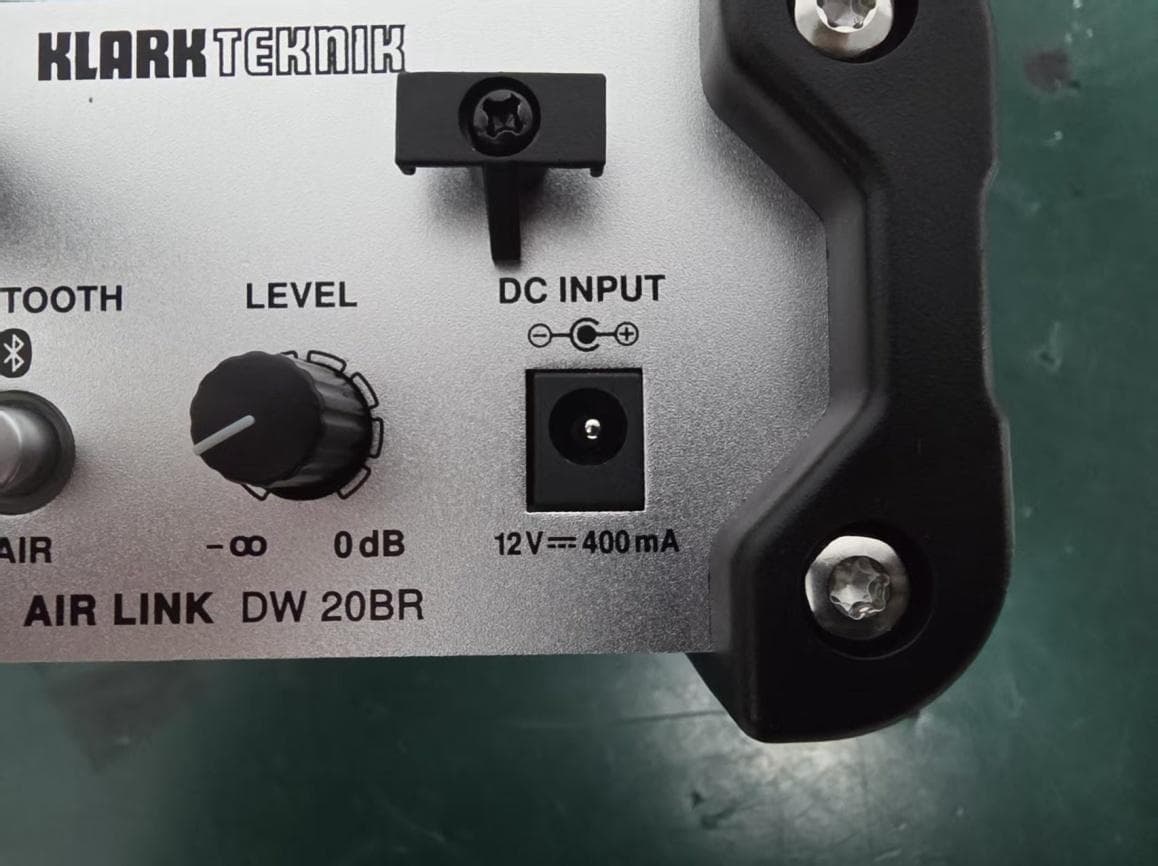
QWHDW20BR1
Mar 29, 2026Wireless DI Boxes
Equipment Class
DSS - Part 15 Spread Spectrum Transmitter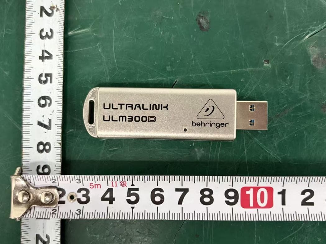
QWHULM300D1
Mar 26, 2026Wireless Microphone System
Equipment Class
DSS - Part 15 Spread Spectrum Transmitter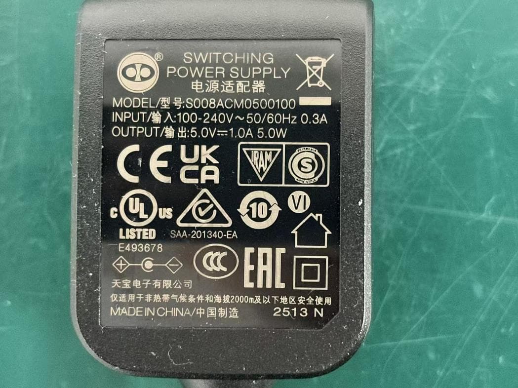
QWHULM300RD
Mar 26, 2026Wireless Microphone System
Equipment Class
DSS - Part 15 Spread Spectrum Transmitter
QWHULM300RS
Mar 25, 2026Wireless Microphone System
Equipment Class
DSS - Part 15 Spread Spectrum Transmitter
QWHULM300M1
Mar 24, 2026Wireless Microphones
Equipment Class
DSS - Part 15 Spread Spectrum Transmitter