FCCID.CO- FCC ID Database
HomeCompaniesEquipment ClassesSearch

© 2026 FCC ID Database. All rights reserved.

AboutContactData sourced from FCC public records
  1. Home/
  2. Hanson Technology Limited/
  3. QXIBINS

QXIBINSBINS

Hanson Technology Limited
BINS - FCC ID QXIBINS - Hanson Technology Limited
Click to zoom

Application Details

Equipment Class
DTS - Digital Transmission System
Date of Grant
Feb 27, 2014
Application Purpose
Original Equipment
Date of Application
Feb 27, 2014
Equipment Note
BINS
Frequency Range
2402.00000000 - 2480.00000000
Company
Hanson Technology Limited
Country
China

Documents & Files

Select a file to view
Users Manual

↗

Block Diagram

↗

Cover Letter(s)

↗

External Photos

↗

ID Label/Location Info

↗

Internal Photos

↗

Operational Description

↗

Schematics

↗

Test Report

↗

Test Setup Photos

↗

Document Text

Text extracted from the exhibit documents filed with the FCC. Open a document above to read the original.

Users Manual

BINS Start Guide ‐ Hanson Technology Limited 1 BINS Quick Start Guide BINS QUICK START GUIDE 1 P ACKAGE INCLUDES.. 2 H OW TO WEAR YOUR BINS 2 F EATURES 2 D ESIGN FOR PERSONALIZATION 2 L ONG BATTERY LIFE 2 W ATER RESISTANT 2 I NTERNAL DATA STORAGE 3 D ATA SYNCHRONIZE WITH MOBILE DEVICE 3 LED INDICATORS 3 S ETTING UP BINS APP SOFTWARE ON A MOBILE DEVICE 3 P OWER CHARGING 5 P RODUCT SPECIFICATION 5 FCC INTERFERENCE STATEMENT 6 BINS Start Guide ‐ Hanson Technology Limited 2 Package includes.. The BINS wristband package includes: z BINS Activity Tracker z Two wristbands with separate colors z Quick start guide z Warranty card How to wear your BINS Wearing Method Hold the BINS tracker, hood A‐side circled buckle around theB‐side BINS body. Length Adjustment 1. Push back and lift themetalbuckleat the back of the BINS face, to release the buckle. 2. According to your own needs, adjust andcut off the extra length of the wristband. There is a pinch that fits the hole of the wristband. 3. After the adjustment, push back and down the metal buckle of the BINS face. This fixes the belt in place. Features Design for personalization Nicely designed wristband with choices of colors suiting to various living styles. Long battery life The product is equipped with a rechargeable lithium‐polymer battery of 85mAh large capacity. For this reason, the operation time can lasts long as 15 days before another charging. It uses standard micro USB power cable commonly used by popular mobile devices. Water resistant IPX4 level water resistant design aims to protect the product from rain, splash, and sweat. BINS Start Guide ‐ Hanson Technology Limited 3 Internal data storage In normal use, the product is able to store more than 20 days of activity records, without any connection to mobile phone devices. Data synchronize with mobile device User can upload the activity data stored in product to the paired mobile device through Bluetooth. Additionally, BINS can be connected to mobile device, by pressing the connection button from phone software, and synchronize the activity data in real time to mobile phone, runs similar like a treadmill. LED Indicators BINS features five LED indicators to display user’s daily activity status. It shows the percentage of the daily goal achieved through the number of LED on. User can activate the display by simply taping the BINS face one time. Setting up BINS APP software on a mobile device The product is capable to connect and work with selected models of mobile devices that support Bluetooth 4.0 technology, includes iPhone series phones from 4s and Google Nexus phones introduced since 2013. For first time use of BINS, please make sure the power is fully charged. The LED flashes on while plugged the power source, and it becomes off after it reaches full charged. ① Find and install the BINS APP on Apple’s App Store or Google’s Google Play,by entering“BINS APP”. ② After the installation, open the BINS APP. The software will automatically prompt a setup guide, to start BINS device pairing and inputs for user’s profile. Search / select the BINS device, and back (<) to previous page. BINS Start Guide ‐ Hanson Technology Limited 4 ③ Exercisegoal setup Users can optionally enter the personal profile data, such asgender, weight and tall length.The information will be used to decide and suggest for a plan of daily exercise goals. And also, the information helps software to calculate measuring datain more accurate ways. ④ Activity data stored in mobile phone BINS APP software has no limit to the record of activity data. ⑤ Display of activity information The software displays daily activity data, by loading user’sactivity records, and calculating calories burned, running distance and very active minutes. By changing the date of the display from the mobile device connected, users are able to check the details of the specific date selected. BINS Start Guide ‐ Hanson Technology Limited 5 Power Charging Plug an external USB power source to the micro USB slot locating on the side of BINS body. The LED indicator will flash on and off to show the charging is working. Thistask may take up to one hour, and LED indicator will be turned off while the charging is completely finished. Product Specification Communication standard: Bluetooth 4.0 (Bluetooth Low Energy) Activity Detection: 3‐axis accelerometer inside Supported Systems of App Software: 1. iOS 6.0 and above (for models of iPhones 4s or later) 2. Android 4.3 and above Dimensions: Tracker device –38x15x8.5mm, Wristband–217 (L) x10 (W) x2mm Weight: 10 grams (g) Power Charging: micro USB with 5V input Water Resistance: IPX4 Level BINS Start Guide ‐ Hanson Technology Limited 6 FCC Interference Statement The device complies with Part 15 of FCC rules. Operation is subject to the following Two conditions: 1. This device may not cause harmful interference. 2. This device must accept any interference received, including interference that may cause undesired operations. This equipment complies with FCC RF radiation exposure limits set forth for An uncontrolled environment. Warning: Changes or modifications to this unit not expressly approved by the party Responsible for compliance could void the user’s authority to operate the Equipment.

Block Diagram

Micro USB connector Power Input BQ24040 Battery charger IC BATTERY Capacity:85MAH Output Voltage3.3~4.2v CSR1010 Bluetooth low energy Single-mode IC XC9236 DCDC : Provide 2.8v voltage Control the Five LED 16Mhz crystals 32.768khz cr y stals Five GPIO MMA8653FC three-axis accelerometer TEST POINT SPI Debug and download I2C BUS and power FW24C256A EEPROM 256k BINS PCB Board BINS_V2 SPI BUS RF Chip Antenna 2402Mhz~2480Mhz

External Photos

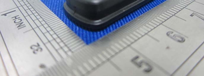
EXHIBIT B - EUT EXTERNAL PHOTOGRAPHS EUT — Difference Color View EUT — Top View EUT — Bottom View EUT —Wristband Off View EUT — Right Side View EUT — Left Side View

ID Label/Location Info

EXHIBIT A - FCC ID LABELING AND LOCATION FCC ID Label Proposed FCC ID Label Location The label shown shall be permanently affixed at a conspicuous location on the device and be readily visible to the user at the time purchase (Labeling requirements per 2.925) Label Here

Internal Photos

EXHIBIT B - EUT EXTERNAL PHOTOGRAPHS EUT - Uncover View EUT - Cover Off View EUT - Battery Top View EUT - Battery Bottom View EUT - Main Board Top View EUT - Main Board Bottom View EUT – Antenna View EUT – RF Chip View

Operational Description

Circuit Principle Description CSR1010 is a SOC component that contains the bluetooth module. At power part, we use XC9236 to reduce battery input voltage to 2.8 V as the power input for CSR1010, MMA8653. The power of the EEPROM (FM24C256A) is controlled by CSR1010 itself, it is used to store the software algorithm and computes data routinely. And BQ24040 is used to charging the battery, 5 v input voltage from the Micro USB and the charging current can be set up between 54 to 270 MA by resistance change. The charging status indicator and CSR1010 GPIO are linked together, the MCU can effectively identify the battery in charging status. MMA8653 is an acceleration sensor, it can detect the human body movement information, at the same time an interrupt to CSR1010. Through the I2C bus communication between CSR1010 and MMA8653, CSR1010 progresses the activity data sent from MMA8653, using specially designed algorithm, and transmits them to the mobile phone by the Bluetooth communication. The five White LEDS is controlled by five GPIO.

Schematics

55 44 33 22 11 D D C C B B A A ANTENNA GSOR_SDAGSOR_SCLGSOR_INT2 GSOR_INT1 I2C_SDAI2C_SCL VCC_ROM I2C_SDAI2C_SCL GSOR_SCLGSOR_INT1 GSOR_SDA UART_TXUART_RXVCC_ROM GPIO4 SPI_MISOSPI_MOSISPI_CS#SPI_CLK SPI_MISOSPI_MOSISPI_CS#SPI_CLK GPIO4 SPI_CLK SPI_MISO SPI_CS# SPI_MOSI Charge Charge BAT_SYS BAT_SYS GSOR_INT2 DVDD DVDD USB_5V SYS_PWR SYS_PWR DVDD SYS_PWR Date: Sheet of 11 Monday, February 17, 2014 Date: Sheet of 11 Monday, February 17, 2014 Date: Sheet of 11 U_TXU_TX C64.7uFC64.7uF G_SCLG_SCL U15 XC9236 U15 XC9236 LX 1 VSS1 2 VOUT/FB 3 CE/MODE 4 VSS2 5 VIN 6 EPAD 7 U14 BQ24040 U14 BQ24040 IN 1 ISET 2 VSS 3 PRETERM 4 PG# 5 OUT 10 TS 9 CHG# 8 ISET2 7 NC 6 EPAD 11 C478P2C478P2 C21150NFC21150NF SPI_CS#T POINT RSPI_CS#T POINT R LED5BLUELED5BLUE 12 R2875RR2875RGNDT POINT RGNDT POINT R L4FBL4FB 1 2 C4615PFC4615PF C20470NFC20470NF C45 10PF C45 10PF R3215kR3215k R24 1.5K R24 1.5K C3833PFC3833PF C19 470NF C19 470NF U1132.768KU1132.768K 1 2 C4410PFC4410PF R224.7kR224.7k C1747NFC1747NF R20 5.6K 1% R20 5.6K 1% C162.2UFC162.2UF R2975RR2975R SPI_selectT POINT RSPI_selectT POINT R SPI_MOSIT POINT RSPI_MOSIT POINT R C511ufC511uf C49100NFC49100NF C1433PFC1433PF R16 0.5pf R16 0.5pf G_SDAG_SDA C110uFC110uF LED4BLUELED4BLUE 12 U12 MMA8653FC U12 MMA8653FC VDD 1 SCL 2 INT1 3 BYP 4 INT2 5 SDA 10 GND1 9 VDDIO 8 GND2 7 GND3 6 C24 NC C24 NC R2575RR2575R R3075RR3075R C51uFC51uF C25 1UF C25 1UF C232.2nHC232.2nH SPI_CLKT POINT RSPI_CLKT POINT R WAKEWAKE LED7BLUELED7BLUE 12 U13 LFB182G45 U13 LFB182G45 GND1 1 OUT 2 GND2 3 IN 4 U_RXU_RX C710UFC710UF L5 4.7UH L5 4.7UH R26 47k R26 47k C31uFC31uF U1016MHZU1016MHZ 13 2 4 C410uFC410uF LED3BLUELED3BLUE 12 R315kR315k C27470NFC27470NF J6 Micro USB J6 Micro USB VBUS 1 D- 2 D+ 3 ID 4 GND2 5 GND3 6 GND4 7 C15 47NF C15 47NF C50 100nf C50 100nf LED6BLUELED6BLUE 12 C222.2UFC222.2UF J9 PAD J9 PAD 1 R2310KR2310K R181.5KR181.5K U8 CSR1010 U8 CSR1010 XTAL_32K_OUT 2 XTAL_32K_IN 3 XTAL_16M_OUT 9 XTAL_16M_IN 10 WAKE 4 AIO[0] 13 AIO[1] 12 AIO[2] 11 RF 7 I2C_SDA 29 I2C_SCL 28 PIO[0]/UART_TX 14 PIO[1]/UART_RX 15 PIO[2] 27 PIO[3]/SF_DIN 16 PIO[4]/SF_CS# 17 PIO[8]/DEBUG_MISO 22 PIO[7]/DEBUG_MOSI 20 PIO[6]/DEBUG_CS# 19 PIO[5]/DEBUG_CLK 18 PIO[11] 25 PIO[10] 24 PIO[9] 23 VDD_BAT 1 VDD_BAT_SMPS 32 SMPS_LX 31 VDD_CORE1 5 VDD_CORE2 30 VDD_PADS 21 VDD_REG_IN 6 VDD_XTAL 8 VSS 33 SPI_PIO# 26 R2775RR2775R L6 4.7UH L6 4.7UH C48 100nf C48 100nf J10 PADJ10 PAD 1 SPI_MISOT POINT RSPI_MISOT POINT R SYS_PWRSYS_PWR DVDDDVDD U9 FW24C256A-DN-T-G U9 FW24C256A-DN-T-G A0 1 A1 2 A2 3 GND 4 VCC 8 WP 7 SCL 6 SDA 5 EPAD 9

Test Report

Note: This test report is prepared for the customer shown above and for the device described herein. It may not be duplicated or used in part without prior written consent from Bay Area Compliance Laboratories Corp. This report must not be used by the customer to claim product certification, approval, or endorsement by NVLAP*, or any agency of the Federal Government. * This report may contain data that are not covered by the NVLAP accreditation and shall be marked with an asterisk “★” (Rev.2), This report is valid only with a valid digital signature. The digital signature may be available only under the Adobe software above version 7.0. FCC PART 15.247 TEST REPORT For Hanson Technology Limited Room 1307, No.1698, Yi Shan Road, Shanghai, 200030, China Report Type: Original Report Product Type: Smart Wr istband Test Engineer: Leon Chen Report Number: R2SH 140218056-00 Report Date: 2014 -02-21 Reviewed By: Ivan Cao RF Leader Test Laboratory: Bay Area Compliance Laboratories Corp. (Dongguan) No.69 Pulongcun, Puxinhu Industrial Zone, Tangxia, Dongguan, Guangdong, China Tel: +86-769-86858888 Fax: +86-769-86858891 www.baclcorp.com.cn FCC ID: QXIBINS Bay Area Compliance Laboratories Corp. (Dongguan) Report No.: R2SH140218056-00 FCC Part 15.247 Page 2 of 33 TABLE OF CONTENTS GENERAL INFORMATION ....................................................................................................................................... 4 PRODUCT DESCRIPTION FOR EQUIPMENT UNDER TEST (EUT) ..................................................................................... 4 OBJECTIVE ................................................................................................................................................................... 4 RELATED SUBMITTAL(S)/GRANT(S) ............................................................................................................................. 4 TEST METHODOLOGY .................................................................................................................................................. 4 TEST FACILITY ............................................................................................................................................................. 4 SYSTEM TEST CONFIGURATION .......................................................................................................................... 6 DESCRIPTION OF TEST CONFIGURATION ...................................................................................................................... 6 EUT EXERCISE SOFTWARE .......................................................................................................................................... 6 EQUIPMENT MODIFICATIONS ....................................................................................................................................... 6 SUPPORT EQUIPMENT LIST AND DETAILS .................................................................................................................... 6 EXTERNAL I/O CABLE .................................................................................................................................................. 6 BLOCK DIAGRAM OF TEST SETUP ................................................................................................................................ 7 SUMMARY OF TEST RESULTS ............................................................................................................................... 8 FCC §15.247 (i) & §1.1310 & §2.1093- RF EXPOSURE ............................................................................................... 9 APPLICABLE STANDARD .............................................................................................................................................. 9 FCC §15.203 - ANTENNA REQUIREMENT ........................................................................................................... 10 APPLICABLE STANDARD ............................................................................................................................................ 10 ANTENNA CONNECTOR CONSTRUCTION .................................................................................................................... 10 FCC §15.207 (a) – AC LINE CONDUCTED EMISSIONS ..................................................................................... 11 APPLICABLE STANDARD ............................................................................................................................................ 11 MEASUREMENT UNCERTAINTY .................................................................................................................................. 11 EUT SETUP ................................................................................................................................................................ 11 EMI TEST RECEIVER SETUP ....................................................................................................................................... 12 TEST PROCEDURE ...................................................................................................................................................... 12 TEST EQUIPMENT LIST AND DETAILS ......................................................................................................................... 12 CORRECTED AMPLITUDE & MARGIN CALCULATION ................................................................................................. 12 TEST RESULTS SUMMARY .......................................................................................................................................... 13 TEST RESULTS SUMMARY .......................................................................................................................................... 13 TEST DATA ..........................................................................................................…

Text truncated - open the document above for the full version.

Test Setup Photos

EXHIBIT D - TEST SETUP PHOTOGRAPHS Conducted Emissions - Front View Conducted Emissions – Side View Radiated Emission -Front View (Below 1GHz) Radiated Emission - Rear View (Below 1GHz) Radiated Emission -Front View (Above 1GHz) Radiated Emission - Rear View (Above 1GHz)

Contact Information

Applicant

Sherry Lai(PM)
[email protected]021-64285069Fax: 021-64285079

Test Firm

Bay Area Compliance Laboratories Corp. (Dongguan)John Chan
[email protected]86-769-86858888

Technical Specifications

#Rule PartsFrequency RangePower Output
115C2.40 GHz - 2.48 GHz240.00 µW
Grant Notes
Output power listed is conducted.

Other Applications from Hanson Technology Limited

Android TV Box - FCC ID QXISURBOX918 - Hanson Technology Limited
QXISURBOX918

Android TV Box

Nov 08, 2012

Equipment Class

DTS - Digital Transmission System